Leuze CR 100 User manual

CR 100
Bar Code Reader
Original operating instructions
EN 2015/01 - 50127908
We reserve the right to
make technical changes

Leuze electronic CR 100 2
© 2015
Leuze electronic GmbH + Co. KG
In der Braike 1
D-73277 Owen / Germany
Phone: +49 7021 573-0
Fax: +49 7021 573-199
http://www.leuze.com

Leuze electronic CR 100 3
1 About this document . . . . . . . . . . . . . . . . . . . . . . . . . . . . . . . . . . . . . . . . . . . . . . 5
1.1 Used symbols and signal words . . . . . . . . . . . . . . . . . . . . . . . . . . . . . . . . . . . . . . . . . . . . . 5
2 Safety . . . . . . . . . . . . . . . . . . . . . . . . . . . . . . . . . . . . . . . . . . . . . . . . . . . . . . . . . . 6
2.1 Intended use . . . . . . . . . . . . . . . . . . . . . . . . . . . . . . . . . . . . . . . . . . . . . . . . . . . . . . . . . . . . 6
2.2 Foreseeable misuse . . . . . . . . . . . . . . . . . . . . . . . . . . . . . . . . . . . . . . . . . . . . . . . . . . . . . . 6
2.3 Competent persons . . . . . . . . . . . . . . . . . . . . . . . . . . . . . . . . . . . . . . . . . . . . . . . . . . . . . . . 6
2.4 Disclaimer . . . . . . . . . . . . . . . . . . . . . . . . . . . . . . . . . . . . . . . . . . . . . . . . . . . . . . . . . . . . . . 7
3 Device description . . . . . . . . . . . . . . . . . . . . . . . . . . . . . . . . . . . . . . . . . . . . . . . . 8
3.1 Device overview . . . . . . . . . . . . . . . . . . . . . . . . . . . . . . . . . . . . . . . . . . . . . . . . . . . . . . . . . 8
3.1.1 The CR 100 bar code reader. . . . . . . . . . . . . . . . . . . . . . . . . . . . . . . . . . . . . . . . . . . . . . . . 8
3.1.2 Stand alone operation . . . . . . . . . . . . . . . . . . . . . . . . . . . . . . . . . . . . . . . . . . . . . . . . . . . . . 8
3.2 Performance characteristics . . . . . . . . . . . . . . . . . . . . . . . . . . . . . . . . . . . . . . . . . . . . . . . . 8
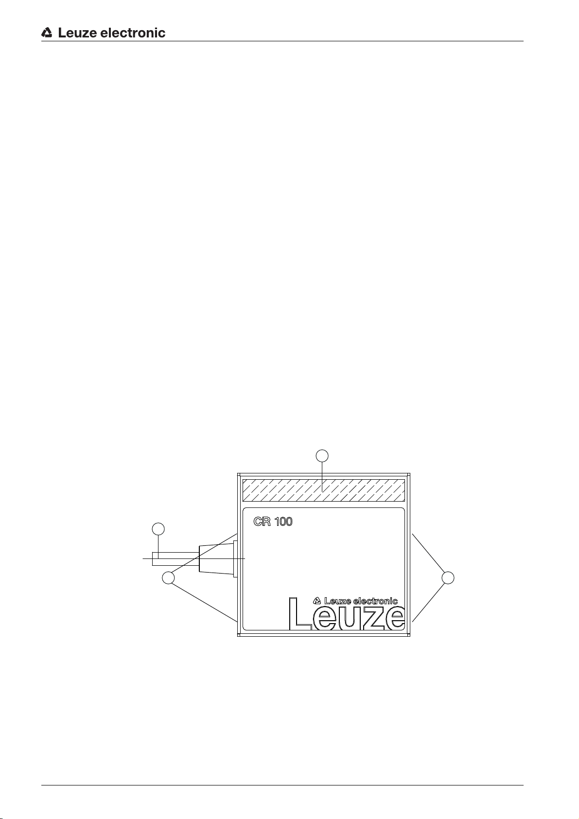
3.3 Device construction . . . . . . . . . . . . . . . . . . . . . . . . . . . . . . . . . . . . . . . . . . . . . . . . . . . . . . . 8
3.4 Connection technology . . . . . . . . . . . . . . . . . . . . . . . . . . . . . . . . . . . . . . . . . . . . . . . . . . . . 9
3.5 Display elements . . . . . . . . . . . . . . . . . . . . . . . . . . . . . . . . . . . . . . . . . . . . . . . . . . . . . . . . . 9
3.5.1 LED indicators . . . . . . . . . . . . . . . . . . . . . . . . . . . . . . . . . . . . . . . . . . . . . . . . . . . . . . . . . . . 9
4 Mounting . . . . . . . . . . . . . . . . . . . . . . . . . . . . . . . . . . . . . . . . . . . . . . . . . . . . . . 10
4.1 Selecting a mounting location . . . . . . . . . . . . . . . . . . . . . . . . . . . . . . . . . . . . . . . . . . . . . . 10
5 Electrical connection . . . . . . . . . . . . . . . . . . . . . . . . . . . . . . . . . . . . . . . . . . . . . 11
5.1 Voltage supply . . . . . . . . . . . . . . . . . . . . . . . . . . . . . . . . . . . . . . . . . . . . . . . . . . . . . . . . . . 11
5.2 Pin assignment of the CR 100 connection cable. . . . . . . . . . . . . . . . . . . . . . . . . . . . . . . . 11
5.3 Switching input/Switching output . . . . . . . . . . . . . . . . . . . . . . . . . . . . . . . . . . . . . . . . . . . . 11
5.3.1 Switching input . . . . . . . . . . . . . . . . . . . . . . . . . . . . . . . . . . . . . . . . . . . . . . . . . . . . . . . . . 11
5.3.2 Switching output . . . . . . . . . . . . . . . . . . . . . . . . . . . . . . . . . . . . . . . . . . . . . . . . . . . . . . . . 12
5.4 PC or terminal connection . . . . . . . . . . . . . . . . . . . . . . . . . . . . . . . . . . . . . . . . . . . . . . . . . 13
5.5 Cable lengths and shielding . . . . . . . . . . . . . . . . . . . . . . . . . . . . . . . . . . . . . . . . . . . . . . . 14
6 Configuration and diagnostic software -
Sensor Studio
. . . . . . . . . . . . . . . . . . . 15
6.1 System requirements. . . . . . . . . . . . . . . . . . . . . . . . . . . . . . . . . . . . . . . . . . . . . . . . . . . . . 15
6.2 Installing
Sensor Studio configuration software
. . . . . . . . . . . . . . . . . . . . . . . . . . . . . . . . . 16
6.2.1 Downloading configuration software . . . . . . . . . . . . . . . . . . . . . . . . . . . . . . . . . . . . . . . . . 16
6.2.2 Installing the
Sensor Studio
FDT frame. . . . . . . . . . . . . . . . . . . . . . . . . . . . . . . . . . . . . . . 16
6.2.3 Intalling communication DTM and device DTM for CR 100. . . . . . . . . . . . . . . . . . . . . . . . 16
6.2.4 Connecting bar code reader to PC . . . . . . . . . . . . . . . . . . . . . . . . . . . . . . . . . . . . . . . . . . 17
6.3 Starting the
Sensor Studio
. . . . . . . . . . . . . . . . . . . . . . . . . . . . . . . . . . . . . . . . . . . . . . . . . 17
6.4 Exiting
Sensor Studio
. . . . . . . . . . . . . . . . . . . . . . . . . . . . . . . . . . . . . . . . . . . . . . . . . . . . 19
6.5 Configuration parameters . . . . . . . . . . . . . . . . . . . . . . . . . . . . . . . . . . . . . . . . . . . . . . . . . 19
6.5.1 Decode tab . . . . . . . . . . . . . . . . . . . . . . . . . . . . . . . . . . . . . . . . . . . . . . . . . . . . . . . . . . . . 20
6.5.2 Output tab . . . . . . . . . . . . . . . . . . . . . . . . . . . . . . . . . . . . . . . . . . . . . . . . . . . . . . . . . . . . . 23
6.5.3 Control tab . . . . . . . . . . . . . . . . . . . . . . . . . . . . . . . . . . . . . . . . . . . . . . . . . . . . . . . . . . . . . 25
6.5.4 Host interface tab . . . . . . . . . . . . . . . . . . . . . . . . . . . . . . . . . . . . . . . . . . . . . . . . . . . . . . . 26
6.5.5 Reference code tab . . . . . . . . . . . . . . . . . . . . . . . . . . . . . . . . . . . . . . . . . . . . . . . . . . . . . . 28
6.5.6 Sensor tab . . . . . . . . . . . . . . . . . . . . . . . . . . . . . . . . . . . . . . . . . . . . . . . . . . . . . . . . . . . . . 30
6.5.7 Switch tab . . . . . . . . . . . . . . . . . . . . . . . . . . . . . . . . . . . . . . . . . . . . . . . . . . . . . . . . . . . . . 31
7 Starting up the device - Configuration . . . . . . . . . . . . . . . . . . . . . . . . . . . . . . . . 32
7.1 Measures to be performed prior to the initial commissioning . . . . . . . . . . . . . . . . . . . . . . 32
7.2 Starting the device. . . . . . . . . . . . . . . . . . . . . . . . . . . . . . . . . . . . . . . . . . . . . . . . . . . . . . . 32
7.2.1 “Power On” test . . . . . . . . . . . . . . . . . . . . . . . . . . . . . . . . . . . . . . . . . . . . . . . . . . . . . . . . . 32

Leuze electronic CR 100 4
7.2.2 Interface. . . . . . . . . . . . . . . . . . . . . . . . . . . . . . . . . . . . . . . . . . . . . . . . . . . . . . . . . . . . . . . 32
7.2.3 “Online commands” . . . . . . . . . . . . . . . . . . . . . . . . . . . . . . . . . . . . . . . . . . . . . . . . . . . . . . 32
7.2.4 Problems . . . . . . . . . . . . . . . . . . . . . . . . . . . . . . . . . . . . . . . . . . . . . . . . . . . . . . . . . . . . . . 32
7.3 Setting the communication parameters . . . . . . . . . . . . . . . . . . . . . . . . . . . . . . . . . . . . . . . 32
7.3.1 Parameter sets . . . . . . . . . . . . . . . . . . . . . . . . . . . . . . . . . . . . . . . . . . . . . . . . . . . . . . . . . 33
7.3.2 “Service” operating mode . . . . . . . . . . . . . . . . . . . . . . . . . . . . . . . . . . . . . . . . . . . . . . . . . 33
8 Online commands . . . . . . . . . . . . . . . . . . . . . . . . . . . . . . . . . . . . . . . . . . . . . . . 34
8.1 Overview of commands and parameters. . . . . . . . . . . . . . . . . . . . . . . . . . . . . . . . . . . . . . 34
8.2 General online commands. . . . . . . . . . . . . . . . . . . . . . . . . . . . . . . . . . . . . . . . . . . . . . . . . 34
8.3 Online commands for system control . . . . . . . . . . . . . . . . . . . . . . . . . . . . . . . . . . . . . . . . 38
8.4 Online commands for the parameter set operations . . . . . . . . . . . . . . . . . . . . . . . . . . . . . 39
9 Care, maintenance and disposal . . . . . . . . . . . . . . . . . . . . . . . . . . . . . . . . . . . . 43
9.1 Cleaning . . . . . . . . . . . . . . . . . . . . . . . . . . . . . . . . . . . . . . . . . . . . . . . . . . . . . . . . . . . . . . 43
9.2 Servicing . . . . . . . . . . . . . . . . . . . . . . . . . . . . . . . . . . . . . . . . . . . . . . . . . . . . . . . . . . . . . . 43
9.3 Disposing. . . . . . . . . . . . . . . . . . . . . . . . . . . . . . . . . . . . . . . . . . . . . . . . . . . . . . . . . . . . . . 43
10 Diagnostics and troubleshooting . . . . . . . . . . . . . . . . . . . . . . . . . . . . . . . . . . . . 44
11 Service and support . . . . . . . . . . . . . . . . . . . . . . . . . . . . . . . . . . . . . . . . . . . . . . 45
11.1 What to do should servicing be required? . . . . . . . . . . . . . . . . . . . . . . . . . . . . . . . . . . . . . 45
12 Technical data . . . . . . . . . . . . . . . . . . . . . . . . . . . . . . . . . . . . . . . . . . . . . . . . . . 46
12.1 General specifications . . . . . . . . . . . . . . . . . . . . . . . . . . . . . . . . . . . . . . . . . . . . . . . . . . . . 46
12.2 Reading fields . . . . . . . . . . . . . . . . . . . . . . . . . . . . . . . . . . . . . . . . . . . . . . . . . . . . . . . . . . 47
12.3 Dimensioned drawings . . . . . . . . . . . . . . . . . . . . . . . . . . . . . . . . . . . . . . . . . . . . . . . . . . . 48
13 Ordering information and accessories . . . . . . . . . . . . . . . . . . . . . . . . . . . . . . . . 50
13.1 Type overview . . . . . . . . . . . . . . . . . . . . . . . . . . . . . . . . . . . . . . . . . . . . . . . . . . . . . . . . . . 50
13.2 Accessories . . . . . . . . . . . . . . . . . . . . . . . . . . . . . . . . . . . . . . . . . . . . . . . . . . . . . . . . . . . . 50
14 EC Declaration of Conformity. . . . . . . . . . . . . . . . . . . . . . . . . . . . . . . . . . . . . . . 51
15 Appendix . . . . . . . . . . . . . . . . . . . . . . . . . . . . . . . . . . . . . . . . . . . . . . . . . . . . . . 52
15.1 Bar code samples . . . . . . . . . . . . . . . . . . . . . . . . . . . . . . . . . . . . . . . . . . . . . . . . . . . . . . . 52

About this document
Leuze electronic CR 100 5
1 About this document
1.1 Used symbols and signal words
Table 1.1: Warning symbols and signal words
Table 1.2: Other symbols
Table 1.3: Terms and abbreviations
Symbol indicating dangers to persons
NOTICE Signal word for property damage
Indicates dangers that may result in property damage if the measures for dan-
ger avoidance are not followed.
Symbol for tips
Text passages with this symbol provide you with further information.
Symbols for action steps
Text passages with this symbol instruct you to perform actions.
BCL Bar code reader
CR CCD based bar code reader
(Code Reader)
DTM Software device manager
(Device Type Manager)
EMC Electromagnetic compatibility
EN European standard
FDT Software frame for management of device managers (DTM)
(Field Device Tool)
FE Functional earth
GUI
Graphical User Interface
IO or I/O Input/Output
LED
Light Emitting Diode
PLC Programmable Logic Control

Safety
Leuze electronic CR 100 6
2 Safety
This sensor was developed, manufactured and tested in line with the applicable safety standards. It corre-
sponds to the state of the art.
2.1 Intended use
The CR 100 bar code reader is designed as a stationary scanner with integrated decoder for all common
bar codes used for automatic object detection.
Areas of application
The CR 100 bar code reader is intended especially for the following areas of application:
• automatic analyzers
• space-critical bar code reading tasks
• automation technology
2.2 Foreseeable misuse
Any use other than that defined under “Intended use” or which goes beyond that use is considered
improper use.
In particular, use of the device is not permitted in the following cases:
• Rooms with explosive atmospheres
• Circuits relevant to safety
• Operation for medical purposes
2.3 Competent persons
Connection, mounting, commissioning and adjustment of the device must only be carried out by competent
persons.
Prerequisites for competent persons:
• They have a suitable technical education.
• They are familiar with the rules and regulations for occupational safety and safety at work.
• They are familiar with the technical description of the device.
• They have been instructed by the responsible person on the mounting and operation of the device.
Certified electricians
Electrical work must be carried out by a certified electrician.
Due to their technical training, knowledge and experience as well as their familiarity with relevant stan-
dards and regulations, certified electricians are able to perform work on electrical systems and indepen-
dently detect possible dangers.
In Germany, certified electricians must fulfill the requirements of accident-prevention regulations BGV A3
(e.g. electrician foreman). In other countries, there are respective regulations that must be observed.
NOTICE
Comply with conditions and regulations!
Observe the locally applicable legal regulations and the rules of the employer's liability insurance asso-
ciation.
NOTICE
Do not modify or otherwise interfere with the device.
Do not carry out modifications or otherwise interfere with the device.
The device must not be tampered with and must not be changed in any way.
The device must not be opened. There are no user-serviceable parts inside.
Repairs must only be performed by Leuze electronic GmbH + Co. KG.

Safety
Leuze electronic CR 100 7
2.4 Disclaimer
Leuze electronic GmbH + Co. KG is not liable in the following cases:
• The device is not being used properly.
• Reasonably foreseeable misuse is not taken into account.
• Mounting and electrical connection are not properly performed.
• Changes (e.g., constructional) are made to the device.

Device description
Leuze electronic CR 100 8
3 Device description
3.1 Device overview
3.1.1 The CR 100 bar code reader
The CR 100 bar code reader is a CCD based line scanner with integrated decoder for all commonly used
bar codes, e.g. 2/5 Interleaved, Code 39, Code 128, EAN etc..
The many possible configurations of the device allow it to be adapted to a multitude of reading tasks. Due
to the small dimensions of the unit and its wide reading field, the CR 100 may also be used in highly
constrained spaces.
Information on technical data and characteristics: see chapter 12.
3.1.2 Stand alone operation
The CR 100 bar code reader is operated as a “standalone” single device. It is equipped with a six-wire
cable with open ends for the electrical connection of the supply voltage, the interface, the switching input
and the switching output.
3.2 Performance characteristics
• High-performance CCD scanner with front or lateral beam exit
• Reading field optimized to a reading field height of 80 mm even at short distances
• Compact design for simple integration, even in constrained spaces
• Scanning rate of 700 scans/s facilitates reliable reading, even while in motion
• Reading of all common codes of modulus sizes 150 – 500 μm (6-20 mil) at a reading field height of
≥ 80 mm
• Robust metal housing with cable connection
• RS 232 interface, one switching input, one switching output
3.3 Device construction
1 Reading window with lateral beam exit
2 Cable, 2000 mm
3 M3 mounting thread
Figure 3.1: CR 100M0 device construction
1
2
33

Device description
Leuze electronic CR 100 9
1 Reading window with front beam exit
2 Cable, 2000 mm
3 M3 mounting thread
Figure 3.2: CR 100M2 device construction
3.4 Connection technology
• Cable connection
• Alternative: customer-specific solutions
3.5 Display elements
On the rear of the CR 100, you will find an LED that indicates the readiness for operation and the read
status of the bar code reader.
3.5.1 LED indicators
A 3-color LED on the rear of the housing indicates the device and read status:
Table 3.1: LED indicators
1
2
3
3
Color State Description
Orange ON (continuous
light)
Reading gate active
Flashing Initialization phase
Green ON (continuous
light)
Reading successful
Red ON (continuous
light)
No read result

Mounting
Leuze electronic CR 100 10
4 Mounting
You can fasten the CR 100 at the M3 mounting threads on both sides of the device.
4.1 Selecting a mounting location
In order to select the right mounting location, several factors must be considered:
• size, orientation, and position tolerance of the bar codes on the objects to be scanned.
• the reading field of the CR 100 in relation to the bar code module width.
• the CR 100 is designed for reading codes in ladder orientation.
• the resulting minimum and maximum reading distance from the respective reading field; see
figure 12.2.
• alignment of the bar code reader for avoiding reflections.
• distance between CR 100 and host system with respect to the interface.
The best read results are obtained when
• the reading distance lies in the middle area of the reading field.
• there is no direct sunlight and extraneous light is avoided.
• the bar code labels are of good print quality and have good contrast ratios.
• you do not use high-gloss labels.
• the bar code is moved past the reading window with a rotational angle of 10° to 15°.
• the red light beam is narrowed down for its respective reading task in order to avoid reflections on
shiny components.
α Azimuth angle
β Angle of inclination
γ Angle of rotation
Recommended angle of rotation: γ > 10°
Figure 4.1: Definition of the CR 100 reading angles
The size of the bar code module influences the maximum reading distance and the width of the
reading field. Therefore, when selecting a mounting location and/or the bar code label, take into
account the different reading characteristics of the scanner with various bar code modules.
NOTICE
Observe when choosing the mounting location!
Maintaining the required environmental conditions (temperature, humidity).
Possible soiling of the reading window due to liquids, abrasion by boxes, or packaging material resi-
dues.
Lowest possible chance of damage to the scanner by mechanical collision or jammed parts.
Possible extraneous light influence (no direct sunlight).
With front beam exit, the beam exit on the CR 100 is nearly vertical to the reading window; with
lateral beam exit, the beam exit is at 13° from vertical. The bar code label must be rotated by
> 10° to avoid a total reflection of the red light beam in the case of glossy labels.
α
β
γ

Electrical connection
Leuze electronic CR 100 11
5 Electrical connection
5.1 Voltage supply
The CR 100 bar code reader is designed for connection to a 5 V supply voltage.
• +5 V DC (red)
• GND (violet)
Available as an accessory is an adapter circuit board with spring terminals and 9-pin SUB-D socket; see
chapter 13.2 "Accessories".
• With the adapter circuit board, the conductors of the CR 100 connection cable can be contacted via
the spring terminals and connected to the PC via the 9-pin SUB-D socket with an RS 232 intercon-
nection cable.
• With the adapter circuit board, the voltage supply from 10 … 30 V DC can be fed in via spring termi-
nals or, alternatively, 5 V DC can be fed in via a micro USB connector.
5.2 Pin assignment of the CR 100 connection cable
5.3 Switching input/Switching output
The CR 100 is provided with a switching input and a switching output. You can configure the functions of
the switching input or switching output according to your needs via the
Sensor Studio
configuration soft-
ware; see chapter 6.
5.3.1 Switching input
By means of the SW IN switching input connection, you can trigger a read process in the standard setting
(low = active) with the connection SW IN (orange) and GND (violet). The 2.2 kΩ “pull-up” resistor must be
connected externally; see figure 5.1.
CAUTION
Safety notices
The CR 100 bar code reader is completely sealed and must not be opened.
Do not try to open the device under any circumstances, as this voids both degree of protection IP 40
and the warranty.
Before connecting the device, be sure that the supply voltage agrees with the value printed on the
name plate.
Connection of the device and maintenance work while under voltage must only be carried out by a
qualified electrician.
The power supply unit for the generation of the supply voltage for the CR 100 and the corresponding
connection units must have a secure electrical insulation according to IEC 60742 (PELV). For UL
applications: only for use in “class 2” circuits according to NEC.
If faults cannot be corrected, the device should be removed from operation and protected against pos-
sible commissioning.
Wire Assignment Description
Red +5V DC Operating voltage 5V DC IN
Violet GND Operating voltage 0V DC / reference ground IN
Black SW OUT Switching output OUT
Orange SW IN Switching input IN
White RS 232 RxD RxD signal line of the RS 232 interface IN
Green RS 232 TxD TxD signal line of the RS 232 interface OUT

Electrical connection
Leuze electronic CR 100 12
Depending on how the switching input is actuated, you can operate it both as NPN (low = active) as well
as PNP (high = active).
1Red
2Orange
3Violet
Connection version NPN: standard setting (low = active); input resistance: 36 kΩ
Figure 5.1: Switching input for CR 100 connection version NPN (standard setting)
PNP actuation: With the "inverted" setting (high = active), you can trigger a read process by applying a
voltage of +5 V DC (red) at SW IN (orange) (see figure 5.2).
1Red
2Orange
3Violet
Connection version PNP: “inverted” setting (high = active); input resistance: 36 kΩ
Figure 5.2: Switching input for CR 100 connection version PNP (setting “inverted”)
5.3.2 Switching output
The NPN switching output connection between SW OUT (black) and GND (violet) can be activated in the
scanner setup.
In the basic setting, the SW OUT switching output is switched to GND if a code is detected.
+ 5 V DC
SW_IN/OUT
GND
4.9 … 5.4 V DC
GND
2.2 k
1
2
3
+ 5 V DC
SW_IN/OUT
GND
GND
4.9 … 5.4 V DC
1
2
3

Electrical connection
Leuze electronic CR 100 13
1Red
2Orange
3Violet
Figure 5.3: Switching output CR 100
5.4 PC or terminal connection
Via the serial interface, you can configure the CR 100 by means of a PC or terminal. For this, you need an
RS 232 connection that establishes the RxD, TxD and GND connections between PC and CR 100.
The RS 232 connection can be established in the following ways:
• Direct connection of the CR 100 connection wires to the PC or terminal via its own connector.
• Connection via an MA-CR adapter circuit board
To simplify the connection of the connection wires to the PC interface, an adapter circuit board (MA-
CR) is available for implementing individual wire contacting to SUB-D, 9-pin; see chapter 13.2.
NOTICE
Maximum loading of the switching output
Do not load the switching output of the CR 100 with more than 20 mA at +5 … 30 V DC!
+ 5 V DC
SW_IN/OUT
GND
GND
+ 5 … 30 V DC
max. 20 mA !
R
L
4.9 … 5.4 V DC
1
2
3

Electrical connection
Leuze electronic CR 100 14
1 RS 232 connection
2 CR 50 connection
3 CR 100 or CR 55 connection
4 Molex Micro-Fit, 6-pin
5 USB connection
6 Connection to machine control, PLC, external voltage supply 5 VDC
7 External voltage supply 10 … 30 VDC
8 SWIN DIP switch (level for trigger button; 5 V if the scanner high switching input is active, GND if the
low input is active)
9 USB/PWR DIP switch (USB position if voltage is supplied via USB; PWR position if voltage is sup-
plied via )
10 Trigger button
11 Status LEDs
Figure 5.4: Connection options for MA-CR adapter circuit board
5.5 Cable lengths and shielding
The maximum cable length is 3 m.
Should a cable extension be necessary, make certain that the cables of the RS 232 interface are shielded.
1
2
10 11
3
4
8
9
5 6 7
7

Configuration and diagnostic software - Sensor Studio
Leuze electronic CR 100 15
6 Configuration and diagnostic software -
Sensor Studio
The
Sensor Studio
configuration software provides a graphical user interface for the operation, configura-
tion and diagnosis of the device via the RS 232 interface.
A device that is not connected to the PC can be configured offline.
Configurations can be saved and reopened as projects for transferring back to the device at a later time.
The
Sensor Studio
configuration software is designed according to the FDT/DTM concept:
• You make the individual configuration settings for the CR 100 bar code reader in the Device Type
Manager (DTM).
• The individual DTM configurations of a project can be called up via the frame application of the Field
Device Tool (FDT).
• Communication DTM for bar code readers:
LeCommInterface
• Device DTM for bar code readers CR 100
Procedure for the installation of the software and hardware:
Install the
Sensor Studio
configuration software on the PC.
Install the communication and device DTM.
Communication and device DTM are included in the
LeAnalysisCollectionSetup
installation package.
Create CR 100-DTM in the project tree of the
Sensor Studio
FDT frame.
Connect the CR 100 to the PC; see chapter 5.4
Activate the service interface on the CR 100; see chapter 7.3.2
6.1 System requirements
To use the
Sensor Studio
configuration software, you need a PC or laptop with the following specifications:
Table 6.1:
System requirements for Sensor Studio
installation
Only use the
Sensor Studio
configuration software for products manufactured by
Leuze electronic.
The
Sensor Studio
configuration software is offered in the following languages: German, Eng-
lish, French, Italian and Spanish.
The FDT frame application of the
Sensor Studio
supports all languages; all languages may not
be supported in the device DTM (Device Type Manager).
Operating system Windows XP or higher (32 bit, 64 bit)
Windows Vista
Windows 7
Windows 8
Computer • Processor type: 1 GHz or higher
• Serial COM interface
• CD drive
• Main memory (RAM): at least 64 MB
• Keyboard and mouse or touchpad
Graphics card At least 1024 x 768 pixels
Required hard disk
capacity for
Sensor Studio
and
communication DTM
35 MB

Configuration and diagnostic software - Sensor Studio
Leuze electronic CR 100 16
6.2 Installing
Sensor Studio configuration software
6.2.1 Downloading configuration software
Call up the Leuze home page: www.leuze.com
Enter the type designation or part number of the device as the search term.
The configuration software can be found on the product page for the device under the
Downloads
tab.
6.2.2 Installing the
Sensor Studio
FDT frame
Start the PC.
Download the configuration software from the Internet to the PC; see chapter 6.2.1.
Unpack the installation package.
Start the
SensorStudioSetup.exe
file.
Follow the instructions on the screen.
The Installation Wizard installs the software and places a shortcut on the desktop ( ).
6.2.3 Intalling communication DTM and device DTM for CR 100
Prerequisites:
• An FDT frame is installed on the PC.
Start the
LeAnalysisCollection.exe
file from the installation package and follow the instructions on the
screen.
The Installation Wizard installs communication DTM and device DTM for CR 100.
Administrator privileges on the PC are necessary for installing
Sensor Studio
.
The installation files of the
Sensor Studio
configuration software must be downloaded from the
Internet at www.leuze.com.
For subsequent updates, you can find the most recent version of the
Sensor Studio
installation
software on the Internet at www.leuze.com.
NOTICE
First install the software!
Do not yet connect the device to the PC.
First install the software.
If FDT frame software is already installed on your PC, you do not need the
Sensor Studio
instal-
lation.
You can install the communication DTM and the device DTM in the existing FDT frame.Commu-
nication DTM and device DTM are included in the
LeAnalysisCollectionSetup
installation pack-
age.

Configuration and diagnostic software - Sensor Studio
Leuze electronic CR 100 17
6.2.4 Connecting bar code reader to PC
The bar code reader is connected to the PC via the RS 232 interface. For this, you need an RS 232
connection that establishes the RxD, TxD and GND connections between PC and CR 100; see
chapter 5.4.
• You need an RS 232 connection that establishes the RxD, TxD and GND connections between PC
and CR 100; see chapter 5.4.
• The 5 V DC voltage supply is to be fed in externally; see chapter 5.1.
6.3 Starting the
Sensor Studio
configuration software
Prerequisites:
• The CR 100 bar code reader has been mounted (see chapter 4) and connected (see chapter 5) cor-
rectly.
• The CR 100 bar code reader is connected to the PC via the RS 232 interface (see chapter 6.2.4).
• The service interface is activated on the CR 100 bar code reader; see chapter 7.3.2
•The
Sensor Studio
configuration software is installed on the PC (see chapter 6.2 "Installing
Sensor Studio configuration software").
Start the
Sensor Studio
configuration software by double-clicking the
Sensor Studio
icon ( ).
The mode selection of the Project Wizard is displayed.
Select the Device selection without communication connection (offline) configuration mode and click on
[Next].
The Project Wizard displays the device selection list of the configurable devices.
The MA-CR adapter circuit board with spring terminals for connecting the CR 100, as well as 9-
pin SUB-D socket for connecting an RS 232 interconnection cable, is available as an accessory.
An RS 232 interconnection cable to the PC is also available as an accessory; see chapter 13
"Ordering information and accessories".
The adapter circuit board requires 10 V … 30 V DC as external voltage supply, which can be fed
in via spring terminals. Alternatively, 5 V DC can be fed in via a micro USB connector.

Configuration and diagnostic software - Sensor Studio
Leuze electronic CR 100 18
Figure 6.1: Device selection for bar code reader CR 100
Select CR 100 in the device selection and click on [Next].
The device manager (DTM) of the connected CR 100 starts with the offline view for the
Sensor Studio
configuration project.
Establish the online connection to the connected CR 100.
In the
Sensor Studio
FDT frame, click on the [Establish connection with device] button ( ).
In the
Sensor Studio
FDT frame, click on the [Upload parameters to device] button ( ).
The current configuration data is displayed in the device manager (DTM).

Configuration and diagnostic software - Sensor Studio
Leuze electronic CR 100 19
Figure 6.2: Configuration project:
Sensor Studio
device manager (DTM) for CR 100
The menus of the
Sensor Studio
device manager (DTM) can be used to change or read out the config-
uration of the connected CR 100.
The user interface of the
Sensor Studio
device manager (DTM) is largely self-explanatory.
The online help system provides information on the menu items and adjustment parameters. Select the
Help menu item in the menu [?] ( ).
Transfer the modified configuration parameters to the device.
If a connection exists, click on the [Download parameters to device] button ( ) on the task bar.
6.4 Exiting
Sensor Studio
After completing the configuration settings, close the
Sensor Studio
configuration software
Exit the program via File > Exit.
Save the configuration settings as a configuration project on the PC.
You can open the configuration project again at later time via File > Open or with the
Sensor Studio
Project
Wizard ( ).
6.5 Configuration parameters
In this chapter, you will find information and explanations on the configuration parameters of the device
manager (DTM) for the CR 100 bar code reader.
This chapter does not include a complete description of the
Sensor Studio
configuration soft-
ware.
Complete information on the FDT frame menu and on the functions in the device manager (DTM)
can be found in the online help system.

Configuration and diagnostic software - Sensor Studio
Leuze electronic CR 100 20
The device manager (DTM) for CR 100 bar code readers of the
Sensor Studio
configuration software
offers the following configuration functions:
•
Decode
; see chapter 6.5.1
•
Output
; see chapter 6.5.2
•
Control;
see chapter 6.5.3
•
Host Interface;
see chapter 6.5.4
•
Reference Code;
see chapter 6.5.5
•
Sensor;
see chapter 6.5.6
•
Switch;
see chapter 6.5.7
6.5.1 Decode tab
Figure 6.3: Decode tab
The online help system displays information on the menu items and configuration parameters for
each function. Select the Help menu item in the menu [?]
Table of contents
Other Leuze Barcode Reader manuals

Leuze
Leuze it 3820 User manual

Leuze
Leuze BCL 308i User manual

Leuze
Leuze BCL604i User manual

Leuze
Leuze BCL 900i User manual

Leuze
Leuze BPS 3007i User manual

Leuze
Leuze BPS 338i User manual

Leuze
Leuze BCL 92 User manual

Leuze
Leuze BCL 300i User manual

Leuze
Leuze BCL 40 Parts list manual

Leuze
Leuze BPS 8 User manual

Leuze
Leuze IT 3800g User manual

Leuze
Leuze BCL 92 User manual

Leuze
Leuze DCR 258i User manual

Leuze
Leuze BPS 348i User manual

Leuze
Leuze BPS 34 User manual

Leuze
Leuze HS 6578 User manual

Leuze
Leuze it 1452g User manual

Leuze
Leuze HS 6508 User manual

Leuze
Leuze BCL 608i SM 102 User manual

Leuze
Leuze BCL 208i User manual