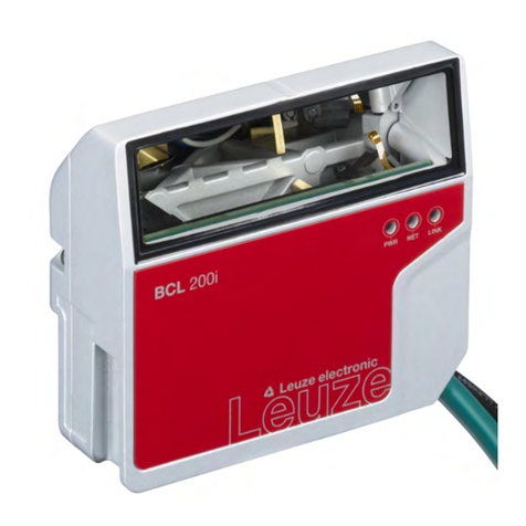
Leuze BCL 608i SM 102 User manual

BCL 608i
Bar code readers
Original operating instructions
EN 2022/07/14 - 50126982
We reserve the right to make technical changes

Leuze electronic GmbH + Co. KG BCL 608
i
2
© 2022
Leuze electronic GmbH + Co. KG
In der Braike 1
D-73277 Owen / Germany
Phone: +49 7021 573-0
Fax: +49 7021 573-199
http://www.leuze.com

Leuze electronic GmbH + Co. KG BCL 608
i
3
1 About this document . . . . . . . . . . . . . . . . . . . . . . . . . . . . . . . . . . . . . . . . . . . . . . 6
1.1 Used symbols and signal words . . . . . . . . . . . . . . . . . . . . . . . . . . . . . . . . . . . . . . . . . . . . . 6
1.2 Declaration of conformity. . . . . . . . . . . . . . . . . . . . . . . . . . . . . . . . . . . . . . . . . . . . . . . . . . . 6
2 Safety . . . . . . . . . . . . . . . . . . . . . . . . . . . . . . . . . . . . . . . . . . . . . . . . . . . . . . . . . . 7
2.1 Intended use . . . . . . . . . . . . . . . . . . . . . . . . . . . . . . . . . . . . . . . . . . . . . . . . . . . . . . . . . . . . 7
2.2 Foreseeable misuse . . . . . . . . . . . . . . . . . . . . . . . . . . . . . . . . . . . . . . . . . . . . . . . . . . . . . . 7
2.3 Competent persons . . . . . . . . . . . . . . . . . . . . . . . . . . . . . . . . . . . . . . . . . . . . . . . . . . . . . . . 7
2.4 Exemption of liability . . . . . . . . . . . . . . . . . . . . . . . . . . . . . . . . . . . . . . . . . . . . . . . . . . . . . . 8
2.5 Laser safety notices. . . . . . . . . . . . . . . . . . . . . . . . . . . . . . . . . . . . . . . . . . . . . . . . . . . . . . . 8
2.5.1 Laser safety notices– laser class 2 . . . . . . . . . . . . . . . . . . . . . . . . . . . . . . . . . . . . . . . . . 8
3 Device description . . . . . . . . . . . . . . . . . . . . . . . . . . . . . . . . . . . . . . . . . . . . . . . 11
3.1 Device overview . . . . . . . . . . . . . . . . . . . . . . . . . . . . . . . . . . . . . . . . . . . . . . . . . . . . . . . . 11
3.2 Performance characteristics . . . . . . . . . . . . . . . . . . . . . . . . . . . . . . . . . . . . . . . . . . . . . . . 11
3.3 Device construction . . . . . . . . . . . . . . . . . . . . . . . . . . . . . . . . . . . . . . . . . . . . . . . . . . . . . . 13
3.4 Connection technology . . . . . . . . . . . . . . . . . . . . . . . . . . . . . . . . . . . . . . . . . . . . . . . . . . . 14
3.5 Display elements . . . . . . . . . . . . . . . . . . . . . . . . . . . . . . . . . . . . . . . . . . . . . . . . . . . . . . . . 14
3.5.1 Structure of the control panel . . . . . . . . . . . . . . . . . . . . . . . . . . . . . . . . . . . . . . . . . . . . 14
3.5.2 Status indicators and operation. . . . . . . . . . . . . . . . . . . . . . . . . . . . . . . . . . . . . . . . . . . 15
3.5.3 LED indicators . . . . . . . . . . . . . . . . . . . . . . . . . . . . . . . . . . . . . . . . . . . . . . . . . . . . . . . . 15
3.6 Operational controls . . . . . . . . . . . . . . . . . . . . . . . . . . . . . . . . . . . . . . . . . . . . . . . . . . . . . 16
3.7 External parameter memory . . . . . . . . . . . . . . . . . . . . . . . . . . . . . . . . . . . . . . . . . . . . . . . 16
4 Functions . . . . . . . . . . . . . . . . . . . . . . . . . . . . . . . . . . . . . . . . . . . . . . . . . . . . . . 17
4.1 autoReflAct . . . . . . . . . . . . . . . . . . . . . . . . . . . . . . . . . . . . . . . . . . . . . . . . . . . . . . . . . . . . 18
4.2 Reference codes . . . . . . . . . . . . . . . . . . . . . . . . . . . . . . . . . . . . . . . . . . . . . . . . . . . . . . . . 18
4.3 autoConfig . . . . . . . . . . . . . . . . . . . . . . . . . . . . . . . . . . . . . . . . . . . . . . . . . . . . . . . . . . . . . 18
4.4 Heating . . . . . . . . . . . . . . . . . . . . . . . . . . . . . . . . . . . . . . . . . . . . . . . . . . . . . . . . . . . . . . . 19
5 Reading techniques . . . . . . . . . . . . . . . . . . . . . . . . . . . . . . . . . . . . . . . . . . . . . . 20
5.1 Line scanner (single line). . . . . . . . . . . . . . . . . . . . . . . . . . . . . . . . . . . . . . . . . . . . . . . . . . 20
5.2 Line scanner with oscillating mirror . . . . . . . . . . . . . . . . . . . . . . . . . . . . . . . . . . . . . . . . . . 20
5.3 Omnidirectional reading. . . . . . . . . . . . . . . . . . . . . . . . . . . . . . . . . . . . . . . . . . . . . . . . . . . 22
5.4 Leuze multiScan over Ethernet/PROFINET . . . . . . . . . . . . . . . . . . . . . . . . . . . . . . . . . . . 22
6 Mounting . . . . . . . . . . . . . . . . . . . . . . . . . . . . . . . . . . . . . . . . . . . . . . . . . . . . . . 24
6.1 Device arrangement . . . . . . . . . . . . . . . . . . . . . . . . . . . . . . . . . . . . . . . . . . . . . . . . . . . . . 24
6.1.1 Selecting a mounting location . . . . . . . . . . . . . . . . . . . . . . . . . . . . . . . . . . . . . . . . . . . . 24
6.1.2 Avoiding total reflection – Line scanner. . . . . . . . . . . . . . . . . . . . . . . . . . . . . . . . . . . . . 24
6.1.3 Avoiding total reflection – oscillating-mirror scanner . . . . . . . . . . . . . . . . . . . . . . . . . . . 25
6.1.4 Possible read angles between device and bar code . . . . . . . . . . . . . . . . . . . . . . . . . . . 25
6.2 Installing the external parameter memory . . . . . . . . . . . . . . . . . . . . . . . . . . . . . . . . . . . . . 26
7 Electrical connection . . . . . . . . . . . . . . . . . . . . . . . . . . . . . . . . . . . . . . . . . . . . . 28
7.1 Overview . . . . . . . . . . . . . . . . . . . . . . . . . . . . . . . . . . . . . . . . . . . . . . . . . . . . . . . . . . . . . . 28
7.2 PWR – Voltage supply and switching inputs/outputs 3 and 4 . . . . . . . . . . . . . . . . . . . . . . 29
7.3 SERVICE – USB interface (type A) . . . . . . . . . . . . . . . . . . . . . . . . . . . . . . . . . . . . . . . . . . 31
7.4 SW IN/OUT – Switching input/switching output. . . . . . . . . . . . . . . . . . . . . . . . . . . . . . . . . 32
7.5 HOST / BUS IN . . . . . . . . . . . . . . . . . . . . . . . . . . . . . . . . . . . . . . . . . . . . . . . . . . . . . . . . . 33
7.6 BUS OUT. . . . . . . . . . . . . . . . . . . . . . . . . . . . . . . . . . . . . . . . . . . . . . . . . . . . . . . . . . . . . . 34

Leuze electronic GmbH + Co. KG BCL 608
i
4
7.7 Ethernet topologies . . . . . . . . . . . . . . . . . . . . . . . . . . . . . . . . . . . . . . . . . . . . . . . . . . . . . . 34
7.7.1 Ethernet wiring . . . . . . . . . . . . . . . . . . . . . . . . . . . . . . . . . . . . . . . . . . . . . . . . . . . . . . . 36
7.8 Cable lengths and shielding . . . . . . . . . . . . . . . . . . . . . . . . . . . . . . . . . . . . . . . . . . . . . . . 36
8 Menu description . . . . . . . . . . . . . . . . . . . . . . . . . . . . . . . . . . . . . . . . . . . . . . . . 37
8.1 The main menus . . . . . . . . . . . . . . . . . . . . . . . . . . . . . . . . . . . . . . . . . . . . . . . . . . . . . . . . 37
8.2 Parameter menu . . . . . . . . . . . . . . . . . . . . . . . . . . . . . . . . . . . . . . . . . . . . . . . . . . . . . . . . 37
8.3 Language selection menu . . . . . . . . . . . . . . . . . . . . . . . . . . . . . . . . . . . . . . . . . . . . . . . . . 44
8.4 Service menu. . . . . . . . . . . . . . . . . . . . . . . . . . . . . . . . . . . . . . . . . . . . . . . . . . . . . . . . . . . 44
8.5 Actions menu. . . . . . . . . . . . . . . . . . . . . . . . . . . . . . . . . . . . . . . . . . . . . . . . . . . . . . . . . . . 44
8.6 Operation. . . . . . . . . . . . . . . . . . . . . . . . . . . . . . . . . . . . . . . . . . . . . . . . . . . . . . . . . . . . . . 46
9 Commissioning – Leuze electronic webConfig tool . . . . . . . . . . . . . . . . . . . . . . 47
9.1 Connecting the service USB interface. . . . . . . . . . . . . . . . . . . . . . . . . . . . . . . . . . . . . . . . 47
9.2 Installation . . . . . . . . . . . . . . . . . . . . . . . . . . . . . . . . . . . . . . . . . . . . . . . . . . . . . . . . . . . . . 47
9.2.1 System requirements . . . . . . . . . . . . . . . . . . . . . . . . . . . . . . . . . . . . . . . . . . . . . . . . . . 47
9.2.2 Installing the USB driver . . . . . . . . . . . . . . . . . . . . . . . . . . . . . . . . . . . . . . . . . . . . . . . . 47
9.3 Starting the webConfig tool . . . . . . . . . . . . . . . . . . . . . . . . . . . . . . . . . . . . . . . . . . . . . . . . 48
9.4 Short description of the webConfig tool. . . . . . . . . . . . . . . . . . . . . . . . . . . . . . . . . . . . . . . 49
9.5 Module overview in the Configuration menu . . . . . . . . . . . . . . . . . . . . . . . . . . . . . . . . . . . 49
10 Starting up the device - Configuration . . . . . . . . . . . . . . . . . . . . . . . . . . . . . . . . 51
10.1 Measures to be performed prior to the initial commissioning . . . . . . . . . . . . . . . . . . . . . . 51
10.2 Starting the device. . . . . . . . . . . . . . . . . . . . . . . . . . . . . . . . . . . . . . . . . . . . . . . . . . . . . . . 51
10.3 Setting the communication parameters. . . . . . . . . . . . . . . . . . . . . . . . . . . . . . . . . . . . . . . 51
10.3.1 Manual configuration of the IP address. . . . . . . . . . . . . . . . . . . . . . . . . . . . . . . . . . . . . 51
10.3.2 Automatically setting the IP address . . . . . . . . . . . . . . . . . . . . . . . . . . . . . . . . . . . . . . . 52
10.3.3 Address Link Label . . . . . . . . . . . . . . . . . . . . . . . . . . . . . . . . . . . . . . . . . . . . . . . . . . . . 52
10.3.4 Ethernet host communication . . . . . . . . . . . . . . . . . . . . . . . . . . . . . . . . . . . . . . . . . . . . 53
10.3.5 TCP/IP. . . . . . . . . . . . . . . . . . . . . . . . . . . . . . . . . . . . . . . . . . . . . . . . . . . . . . . . . . . . . . 53
10.3.6 UDP. . . . . . . . . . . . . . . . . . . . . . . . . . . . . . . . . . . . . . . . . . . . . . . . . . . . . . . . . . . . . . . . 54
10.4 Further settings . . . . . . . . . . . . . . . . . . . . . . . . . . . . . . . . . . . . . . . . . . . . . . . . . . . . . . . . . 55
10.4.1 Decoding and processing the read data . . . . . . . . . . . . . . . . . . . . . . . . . . . . . . . . . . . . 55
10.4.2 Control of the decoding . . . . . . . . . . . . . . . . . . . . . . . . . . . . . . . . . . . . . . . . . . . . . . . . . 55
10.4.3 Control of the switching outputs . . . . . . . . . . . . . . . . . . . . . . . . . . . . . . . . . . . . . . . . . . 56
10.5 Transmitting configuration data . . . . . . . . . . . . . . . . . . . . . . . . . . . . . . . . . . . . . . . . . . . . . 56
10.5.1 Via the webConfig tool . . . . . . . . . . . . . . . . . . . . . . . . . . . . . . . . . . . . . . . . . . . . . . . . . 57
10.5.2 With the external parameter memory . . . . . . . . . . . . . . . . . . . . . . . . . . . . . . . . . . . . . . 57
11 Online commands . . . . . . . . . . . . . . . . . . . . . . . . . . . . . . . . . . . . . . . . . . . . . . . 58
11.1 General online commands. . . . . . . . . . . . . . . . . . . . . . . . . . . . . . . . . . . . . . . . . . . . . . . . . 58
11.2 Online commands for system control . . . . . . . . . . . . . . . . . . . . . . . . . . . . . . . . . . . . . . . . 63
11.3 Online commands for the parameter set operations . . . . . . . . . . . . . . . . . . . . . . . . . . . . . 64
12 Care, maintenance and disposal . . . . . . . . . . . . . . . . . . . . . . . . . . . . . . . . . . . . 71
12.1 Cleaning . . . . . . . . . . . . . . . . . . . . . . . . . . . . . . . . . . . . . . . . . . . . . . . . . . . . . . . . . . . . . . 71
12.2 Servicing . . . . . . . . . . . . . . . . . . . . . . . . . . . . . . . . . . . . . . . . . . . . . . . . . . . . . . . . . . . . . . 71
12.3 Disposing. . . . . . . . . . . . . . . . . . . . . . . . . . . . . . . . . . . . . . . . . . . . . . . . . . . . . . . . . . . . . . 71
13 Diagnostics and troubleshooting . . . . . . . . . . . . . . . . . . . . . . . . . . . . . . . . . . . . 72
13.1 General causes of errors . . . . . . . . . . . . . . . . . . . . . . . . . . . . . . . . . . . . . . . . . . . . . . . . . . 72
13.2 Interface errors . . . . . . . . . . . . . . . . . . . . . . . . . . . . . . . . . . . . . . . . . . . . . . . . . . . . . . . . . 72

Leuze electronic GmbH + Co. KG BCL 608
i
5
14 Service and support . . . . . . . . . . . . . . . . . . . . . . . . . . . . . . . . . . . . . . . . . . . . . . 73
15 Technical data . . . . . . . . . . . . . . . . . . . . . . . . . . . . . . . . . . . . . . . . . . . . . . . . . . 74
15.1 General specifications . . . . . . . . . . . . . . . . . . . . . . . . . . . . . . . . . . . . . . . . . . . . . . . . . . . . 74
15.1.1 Line scanner . . . . . . . . . . . . . . . . . . . . . . . . . . . . . . . . . . . . . . . . . . . . . . . . . . . . . . . . . 74
15.1.2 Oscillating-mirror scanner . . . . . . . . . . . . . . . . . . . . . . . . . . . . . . . . . . . . . . . . . . . . . . . 76
15.2 Heating models of the bar code readers . . . . . . . . . . . . . . . . . . . . . . . . . . . . . . . . . . . . . . 76
15.2.1 Line scanner with heater . . . . . . . . . . . . . . . . . . . . . . . . . . . . . . . . . . . . . . . . . . . . . . . . 77
15.2.2 Oscillating-mirror scanner with heating . . . . . . . . . . . . . . . . . . . . . . . . . . . . . . . . . . . . . 78
15.3 Dimensioned drawings . . . . . . . . . . . . . . . . . . . . . . . . . . . . . . . . . . . . . . . . . . . . . . . . . . . 79
15.4 Dimensioned drawings: Accessories. . . . . . . . . . . . . . . . . . . . . . . . . . . . . . . . . . . . . . . . . 81
15.5 Reading field curves / optical data. . . . . . . . . . . . . . . . . . . . . . . . . . . . . . . . . . . . . . . . . . . 82
15.6 Reading field curves . . . . . . . . . . . . . . . . . . . . . . . . . . . . . . . . . . . . . . . . . . . . . . . . . . . . . 82
15.6.1 Medium Density (M) - optics . . . . . . . . . . . . . . . . . . . . . . . . . . . . . . . . . . . . . . . . . . . . . 84
15.6.2 Low Density (F) - optics. . . . . . . . . . . . . . . . . . . . . . . . . . . . . . . . . . . . . . . . . . . . . . . . . 85
15.7 Reading field curves for heating devices. . . . . . . . . . . . . . . . . . . . . . . . . . . . . . . . . . . . . . 86
15.7.1 Medium Density (M) - optics: (with heating) . . . . . . . . . . . . . . . . . . . . . . . . . . . . . . . . . 87
15.7.2 Medium Density (M) - optics: (with heating) . . . . . . . . . . . . . . . . . . . . . . . . . . . . . . . . . 87
15.7.3 Low Density (F) - optics: (with heating) . . . . . . . . . . . . . . . . . . . . . . . . . . . . . . . . . . . . . 89
15.7.4 Low Density (F) - optics: (with heating) . . . . . . . . . . . . . . . . . . . . . . . . . . . . . . . . . . . . . 90
16 Order guide and accessories . . . . . . . . . . . . . . . . . . . . . . . . . . . . . . . . . . . . . . . 92
16.1 Nomenclature . . . . . . . . . . . . . . . . . . . . . . . . . . . . . . . . . . . . . . . . . . . . . . . . . . . . . . . . . . 92
16.2 Type overview . . . . . . . . . . . . . . . . . . . . . . . . . . . . . . . . . . . . . . . . . . . . . . . . . . . . . . . . . . 92
16.3 Accessories . . . . . . . . . . . . . . . . . . . . . . . . . . . . . . . . . . . . . . . . . . . . . . . . . . . . . . . . . . . . 93
17 Appendix . . . . . . . . . . . . . . . . . . . . . . . . . . . . . . . . . . . . . . . . . . . . . . . . . . . . . . 94
17.1 ASCII character set . . . . . . . . . . . . . . . . . . . . . . . . . . . . . . . . . . . . . . . . . . . . . . . . . . . . . . 94
17.2 Bar code samples . . . . . . . . . . . . . . . . . . . . . . . . . . . . . . . . . . . . . . . . . . . . . . . . . . . . . . . 98
17.2.1 Module 0.3. . . . . . . . . . . . . . . . . . . . . . . . . . . . . . . . . . . . . . . . . . . . . . . . . . . . . . . . . . . 98
17.2.2 Module 0.5. . . . . . . . . . . . . . . . . . . . . . . . . . . . . . . . . . . . . . . . . . . . . . . . . . . . . . . . . . . 99

Leuze electronic GmbH + Co. KG BCL 608
i
6
1 About this document
1.1 Used symbols and signal words
Table 1.1: Warning symbols and signal words
Table 1.2: Other symbols
Table 1.3: Terms and abbreviations
1.2 Declaration of conformity
The bar code readers of the BCL 600
i
series have been developed and manufactured in accordance with
the applicable European standards and directives.
The manufacturer of the product, Leuze electronic GmbH + Co. KG in D-73277 Owen, possesses a certi-
fied quality assurance system in accordance with ISO 9001.
Symbol indicating dangers to persons
NOTE Signal word for property damage
Indicates dangers that may result in property damage if the measures for dan-
ger avoidance are not followed.
Symbol for tips
Text passages with this symbol provide you with further information.
Symbol for action steps
Text passages with this symbol instruct you to perform actions.
BCL Bar code reader
CRT Code reconstruction technology
NOTE
The Declaration of Conformity for these devices can be requested from the manufacturer.

Leuze electronic GmbH + Co. KG BCL 608
i
7
2 Safety
This sensor was developed, manufactured and tested in line with the applicable safety standards. It corre-
sponds to the state of the art.
2.1 Intended use
The device is designed as a stationary high-speed scanner with integrated decoder for all common bar
codes for automatic object detection.
Areas of application
The device is specially designed for the following areas of application:
• Object identification on fast-moving conveyor lines
• Omnidirectional reading
2.2 Foreseeable misuse
Any use other than that defined under "Intended use" or which goes beyond that use is considered
improper use.
In particular, use of the device is not permitted in the following cases:
• in rooms with explosive atmospheres
• in circuits which are relevant to safety
• for medical purposes
2.3 Competent persons
Connection, mounting, commissioning and adjustment of the device must only be carried out by competent
persons.
Prerequisites for competent persons:
• They have a suitable technical education.
• They are familiar with the rules and regulations for occupational safety and safety at work.
• They are familiar with the technical description of the device.
• They have been instructed by the responsible person on the mounting and operation of the device.
Certified electricians
Electrical work must be carried out by a certified electrician.
Due to their technical training, knowledge and experience as well as their familiarity with relevant stan-
dards and regulations, certified electricians are able to perform work on electrical systems and indepen-
dently detect possible dangers.
In Germany, certified electricians must fulfill the requirements of accident-prevention regulations BGV A3
(e.g. electrician foreman). In other countries, there are respective regulations that must be observed.
CAUTION!
Comply with conditions and regulations!
Observe the locally applicable legal regulations and the rules of the employer's liability insur-
ance association.
CAUTION!
Do not modify or otherwise interfere with the device!
Do not carry out modifications or otherwise interfere with the device.
The device must not be tampered with and must not be changed in any way.
The device must not be opened. There are no user-serviceable parts inside.
Repairs must only be performed by Leuze electronic GmbH + Co. KG.

Leuze electronic GmbH + Co. KG BCL 608
i
8
2.4 Exemption of liability
Leuze electronic GmbH + Co. KG is not liable in the following cases:
• The device is not being used properly.
• Reasonably foreseeable misuse is not taken into account.
• Mounting and electrical connection are not properly performed.
• Changes (e.g., constructional) are made to the device.
2.5 Laser safety notices
2.5.1 Laser safety notices– laser class 2
ATTENTION, LASER RADIATION – CLASS 2 LASER PRODUCT
Do not stare into beam
The device satisfies the requirements of IEC/EN 60825-1:2014 safety regulations for a product
of laser class 2 and complies with 21 CFR 1040.10 except for conformance with IEC 60825-1
Ed. 3., as described in Laser Notice No. 56, dated May 8, 2019.
Never look directly into the laser beam or in the direction of reflected laser beams!
If you look into the beam path over a longer time period, there is a risk of injury to the retina.
Do not point the laser beam of the device at persons!
Interrupt the laser beam using a non-transparent, non-reflective object if the laser beam is
accidentally directed towards a person.
When mounting and aligning the device, avoid reflections of the laser beam off reflective sur-
faces!
CAUTION! Use of controls or adjustments or performance of procedures other than specified
herein may result in hazardous light exposure.
Observe the applicable statutory and local laser protection regulations.
The device must not be tampered with and must not be changed in any way.
There are no user-serviceable parts inside the device.
Repairs must only be performed by Leuze electronic GmbH + Co.
The bar code reader emits a moving laser beam that scans with a beam spread of 60°. Here,
the laser is operated in CW mode. A scanning laser beam in CW mode creates the perception
of repeating laser impulses if you inadvertently look into the beam. At a distance of 60 mm
from the exit window, pulse durations <150 µs with a pulse power of 2 mW would be received
by the eye of the observer. The mean laser power is <1 mW and the wavelength is 405 nm
(see figure 2.3).
NOTE
Affix laser information and warning signs!
Laser information and warning signs attached to the device.
Also included with the device are self-adhesive laser warning and laser information signs (stick-
on labels) in multiple languages.
Affix the laser information sheet to the device in the language appropriate for the place of use.
When using the device in the U.S.A., use the stick-on label with the "Complies with
21 CFR 1040.10" notice.
Affix the laser information and warning signs near the device if no signs are attached to the
device (e.g., because the device is too small) or if the attached laser information and warning
signs are concealed due to the installation position.
Affix the laser information and warning signs so that they are legible without exposing the
reader to the laser radiation of the device or other optical radiation.

Leuze electronic GmbH + Co. KG BCL 608
i
9
1 Laser aperture
2 Laser warning sign
3 Laser information sign with laser parameters
Figure 2.1: Laser aperture, laser warning and information signs - line scanner
1 Laser aperture
2 Laser warning sign
3 Laser information sign with laser parameters
Figure 2.2: Laser aperture, laser warning and information signs - oscillating-mirror scanner
LASER RADIATION
DO NOT STARE INTO BEAM
Maximum Output (peak):
Pulse duration:
Wavelength:
2 mW
<150 µs
405 nm
AVOID EXPOSURE – LASER RADIATION
IS EMITTED FROM THIS APERTURE
2 3
1
CLASS 2 LASER PRODUCT
IEC 60825-1:2014
Complies with 21 CFR 1040.10
LASER RADIATION
DO NOT STARE INTOBEAM
Maximum Output (peak):
Pulse duration:
Wavelength:
2 mW
<150 μs
405 nm
AVOID EXPOSURE – LASER RADIATION
IS EMITTED FROM THIS APERTURE
2 3
1
CLASS 2 LASER PRODUCT
IEC 60825-1:2014
Complies with 21 CFR 1040.10

Leuze electronic GmbH + Co. KG BCL 608
i
10
Figure 2.3: Laser warning and information signs – supplied stick-on labels
LASERSTRAHLUNG
NICHT IN DEN STRAHL BLICKEN
LASER KLASSE 2
EN 60825-1:2014
Max. Leistung (peak):
Impulsdauer:
Wellenlänge:
RADIAZIONE LASER
NON FISSARE IL FASCIO
APARRECCHIO LASER DI CLASSE 2
EN 60825-1:2014
Potenza max. (peak):
Durata dell'impulso:
Lunghezza d'onda:
LASER RADIATION
DO NOT STARE INTO BEAM
CLASS 2 LASER PRODUCT
EN 60825-1:2014
Maximum Output (peak):
Pulse duration:
Wavelength:
RAYONNEMENT LASER
NE PAS REGARDER DANS LE FAISCEAU
APPAREIL À LASER DE CLASSE 2
EN 60825-1:2014
Puissance max. (crête):
Durée d`impulsion:
Longueur d`onde:
RADIACIÓN LÁSER
NO MIRAR FIJAMENTE AL HAZ
PRODUCTO LÁSER DE CLASE 2
EN 60825-1:2014
Potencia máx. (peak):
Duración del impulso:
Longitud de onda:
RADIAÇÃO LASER
NÃO OLHAR FIXAMENTE O FEIXE
EQUIPAMENTO LASER CLASSE 2
EN 60825-1:2014
Potência máx. (peak):
Período de pulso:
Comprimento de onda:
LASER RADIATION
DO NOT STARE INTO BEAM
CLASS 2 LASER PRODUCT
IEC 60825-1:2014
Complies with 21 CFR 1040.10
Maximum Output (peak):
Pulse duration:
Wavelength:
䉏⏘戟⺓
▎䦃展⏘㧮
伊䉏⏘ℶ❐
IEC 60825-1:2014
㦏⮶戢⒉᧤⽿⋋᧥
厘⑁㖐兼㢅梃
㽱栎
2 mW
<150 µs
405 nm
2 mW
<150 µs
405 nm
2 mW
<150 µs
405 nm
2 mW
<150 µs
405 nm
2 mW
<150 µs
405 nm
2 mW
<150 µs
405 nm
2 mW
<150 µs
405 nm
2 mW
<150 µs
405 nm
50127630-01

Leuze electronic GmbH + Co. KG BCL 608
i
11
3 Device description
3.1 Device overview
Bar code readers of the BCL 600
i
series are high-speed scanners with integrated decoder for all
commonly used bar codes, e.g. 2/5 Interleaved, Code 39, Code 128, EAN 8/13 etc., as well as codes from
the GS1 DataBar family.
Bar code readers of the BCL 600
i
series are available in various optics models as well as line scanners
and oscillating mirrors and also optionally as heated models.
1 Line scanner
2 Oscillating-mirror scanner
Figure 3.1: Line scanner and oscillating-mirror scanner
The extensive options for device configuration via display or software enable adaptation to a multitude of
reading tasks. Due to the large reading distance combined with the great depth of field and a very compact
construction, the device is ideally suited for package and pallet transportation systems. In general, the bar
code readers of the BCL 600
i
series are designed for the conveyor and storage technology market.
The interfaces (RS 232, RS 485 and RS 422) integrated in the various device models and the fieldbus
systems (Profibus DP, PROFINET-IO, Ethernet TCP/IP / UDP and Ethernet/IP) of the BCL 600
i
series bar
code readers offer optimum connection to the superior host system.
3.2 Performance characteristics
• Integrated fieldbus connectivity = i -> Plug-and-Play fieldbus coupling and easy networking
• Numerous interface variants facilitate connection to the superior systems
•RS 232, RS 422 as well as with integrated multiNet plus master
•RS 485 and multiNet plus slave
Alternatively, various fieldbus systems, such as
PROFINET-IO
Ethernet TCP/IP
Ethernet/IP
Profibus
2
1

Leuze electronic GmbH + Co. KG BCL 608
i
12
• Integrated code reconstruction technology (CRT) enables the identification of soiled or damaged bar
codes
• Maximum depth of field and reading distances from 400 mm to 1450 mm
• Large optical opening angle and, thus, large reading field width
• High scanning rate of 800 / 1000 scans/s for fast reading tasks
• Intuitive, backlit, multi-language display with user-friendly menu navigation
• Integrated USB 1.1 service interface
• Adjustment of all device parameters with a web browser
• Connection options for an external parameter memory
• Easy alignment and diagnostics functions
• M12 connections with Ultra-Lock ™ technology
• Four freely programmable switching inputs/outputs for the activation or signaling of states
• Automatic monitoring of the read quality with autoControl
• Automatic recognition and setting of the bar code type using autoConfig
• Reference code comparison
• Optional heating models to -35 °C
• Heavy-duty housing of degree of protection IP 65

Leuze electronic GmbH + Co. KG BCL 608
i
13
3.3 Device construction
1 Reading window
2 Control panel with display, LEDs and buttons
3 M12 connection technology
4 USB interface
5 Dovetail mounting
6 M4 mounting thread
Figure 3.2: Device construction
1
1
2
3
5
6
4
66

Leuze electronic GmbH + Co. KG BCL 608
i
14
3.4 Connection technology
The bar code readers are connected using variously coded M12 connectors. This ensures unique connec-
tion assignments.
The additional USB interface is used for configuring the device.
For the locations of the individual device connections, please refer to the device detail shown below.
1 Service, USB socket, type A
2 SW IN/OUT, M12 socket (A-coded)
3 BUS OUT, M12 socket (D-coded)
4 Host/BUS IN, M12 socket (D-coded)
5 PWR, M12 connector (A-coded)
Figure 3.3: Location of the electrical connections
3.5 Display elements
3.5.1 Structure of the control panel
1PWR LED
2 NET LED
3 Navigation buttons
4 Escape button
5 Enter button
6 Display
Figure 3.4: Structure of the control panel
3 4 5
2
1
3
2
1
4
5
6

Leuze electronic GmbH + Co. KG BCL 608
i
15
3.5.2 Status indicators and operation
Indicators in the display
Table 3.1: Status displays of the switching inputs/outputs
Table 3.2: Status display of the USB interface
Read result
The read bar code information is displayed.
3.5.3 LED indicators
PWR LED
IO1 Switching input or switching output 1 active (function dependent on set configuration).
Default: Switching input with the "Reading gate activation" function
IO2 Switching input or switching output 2 active (function dependent on set configuration).
Default: Input with the "Teach-in" function
IO3 Switching input or switching output 3 active (function dependent on set configuration).
Default: Switching input with the "Reading gate activation" function
IO4 Switching input or switching output 4 active (function dependent on set configuration).
Default: Switching output with the "No read" function
ATT Warning (Attention)
ERR Internal device error (Error) -> The device must be sent in for inspection
USB The device is connected to a PC via the USB interface.
MS An external parameter memory is properly connected to the USB interface of the device.
Off Device OFF
• No supply voltage
Flashes green Device ok, initialization phase
• No bar code reading possible
• Voltage connected
• Self test running
• Initialization running
Green, continu-
ous light
Device ok
• Bar code reading possible
• Self test successfully finished
• Device monitoring active
Orange, continu-
ous light
Service mode
• Bar code reading possible
• Configuration via the USB service interface
• Configuration via the display
• No data on the host interface
Flashes red Device ok, warning set
• Bar code reading possible
• Temporary operating fault
Red, continuous
light
Device error / parameter enable
• No bar code reading possible

Leuze electronic GmbH + Co. KG BCL 608
i
16
NET LED
3.6 Operational controls
Navigating within the menus
Use the navigation buttons to move through the menu. Activate the desired selection with the enter
button .
Press the escape button to move up one menu level.
When one of the buttons is actuated, the display illumination is activated for 10 min.
Setting values
Set the desired value with the navigation buttons and the enter button .
An accidental incorrect entry can be corrected by selecting the left arrow button and then pressing the
enter button.
Then use the navigation buttons to select save and save the set value by pressing the enter button.
Selecting options
Set the desired option with the navigation buttons and the enter button .
3.7 External parameter memory
The optionally available external parameter memory – based on a USB memory stick (compatible with
version 1.1) – is housed in an external hood with integrated connectors which cover the USB service inter-
face when installed (IP 65).
The external parameter memory makes it easy and reduces the time needed to replace a device on site
by providing a copy of the current parameter set of the device. This eliminates the need to configure the
exchanged device manually.
The delivery contents of the external parameter memory include the hood with integrated connectors with
unscrewable cover and the USB memory stick.
For transferring the configuration with the aid of the external parameter memory see chapter 6.2.
Off No supply voltage
• No communication possible
• Ethernet protocols not released
Flashes green Initialization
• Of the device, establishing communication
Green, continu-
ous light
Operation ok
• Network mode ok
• Connection and communication to Host established
Flashes red Communication error
• temporary connection error
• If DHCP is active, no address could be obtained
Red, continuous
light
Network error
• Network error
• No connection established
• No communication possible
ESC
NOTE
To mount, the cover of the service interface must be unscrewed. T h e n s c r e w t h e t u b e b o d y o n t o
the USB connection on the device and plug the USB memory stick i n t o t h e c o n n e c t i o n a n d c l o s e
the connector hood with the cover to ensure degree of protection IP 65.

Leuze electronic GmbH + Co. KG BCL 608
i
17
4 Functions
General information
The integrated fieldbus connectivity = i contained in the bar code readers of the BCL 600
i
series facilitates
the use of identification systems which function without connection unit or gateways. The integrated
fieldbus interface considerably simplifies handling. The Plug-and-Play concept enables easy networking
and very simple commissioning: Directly connect the respective fieldbus and all configuration is performed
with no additional software.
For decoding bar codes, the bar code readers of the BCL 600
i
series make available the proven CRT
decoder with code reconstruction technology:
The proven code reconstruction technology (CRT) enables bar code readers of the BCL 600
i
series to read
bar codes with a small bar height, as well as bar codes with a damaged or soiled print image.
With the aid of the CRT decoder, bar codes can also be read without problem in other demanding situa-
tions, such as with a large tilt angle (azimuth angle or even angle of rotation).
Figure 4.1: Possible bar code orientation
The device needs a suitable activation to start a read process as soon as an object is in the reading field.
This opens a time window (reading gate) in the device for the read process during which the bar code
reader has time to detect and decode a bar code.
In the basic setting, triggering takes place through an external reading cycle signal. Alternative activation
options include online commands via the host interface and the autoReflAct function. Through the read
operation, the device collects additional useful pieces of data for diagnostics which can also be transmitted
to the host. The quality of the read operation can be inspected using the alignment mode which is inte-
grated in the webConfig tool.
A multi-language display with buttons is used to operate the device as well as for visualization purposes.
Two LEDs provide additional optical information on the current operating state of the device.
The four freely configurable switching inputs/outputs SWIO 1 … SWIO 4 can be assigned various func-
tions and control e.g. activation of the device or external devices, such as a PLC.
System, warning and error messages provide assistance in setup/troubleshooting during commissioning
and read operation.

Leuze electronic GmbH + Co. KG BCL 608
i
18
4.1 autoReflAct
autoReflAct stands for automatic Reflector Activation and permits an activation without additional sensors.
This is achieved by directing the scanner with reduced scanning beam towards a reflector mounted behind
the conveyor path. As long as the scanner is targeted at the reflector, the reading gate remains closed. If,
however, the reflector is blocked by an object such as a container with a bar code label, the scanner acti-
vates the read procedure, and the label on the container is read. When the path from the scanner to the
reflector has cleared, the read procedure has completed and the scanning beam is reduced and again
directed onto the reflector. The reading gate is closed.
Figure 4.2: Reflector arrangement for autoReflAct
The autoReflAct function uses the scanning beam to simulate a photoelectric sensor and thus permits an
activation without additional sensors.
4.2 Reference codes
The device offers the possibility of storing one or two reference codes.
It is possible to store the reference codes by means of teach-in (display command), via the webConfig tool
or via online commands.
The device can compare read bar codes with one and/or both reference codes and execute user-config-
urable functions depending on the comparison result.
4.3 autoConfig
With the autoConfig function, the device offers an extremely simple and convenient configuration option
to users who only want to read one code type (symbology) with one number of digits at a time.
After starting the autoConfig function via the display, switching input or from a superior control, it is suffi-
cient to position a bar code label with the desired code type and number of digits in the reading field of the
device.
Afterward, bar codes with the same code type and number of digits are recognized and decoded.
NOTE
You will find a matching reflector in Accessories, and more are available on request.

Leuze electronic GmbH + Co. KG BCL 608
i
19
For further information, see chapter 10 "Starting up the device - Configuration".
4.4 Heating
For low-temperature applications to min. -35°C (e.g. in cold storage), the bar code readers of the BCL 600
i
series can optionally be permanently fitted with a built-in heating and these bar code readers purchased
as separate device models.

Leuze electronic GmbH + Co. KG BCL 608
i
20
5 Reading techniques
5.1 Line scanner (single line)
A line (scan line) scans the label. Due to the opt. opening angle, the reading field width is dependent on
the read distance. Through the movement of the object, the entire bar code is automatically transported
through the scan line.
The integrated code reconstruction technology permits twisting of the bar code (tilt angle) within certain
limits. These are dependent on the transport speed, the scanning rate of the scanner and the bar code
properties.
Areas of application of the line scanner
The line scanner is used:
• When the bars of the bar code are printed in the conveying direction ('ladder arrangement').
• With bar codes having very short bar lengths.
• When the ladder code is turned out of the vertical position (tilt angle).
• When the reading distance is large.
Figure 5.1: Deflection principle for the line scanner
5.2 Line scanner with oscillating mirror
The oscillating mirror deflects the scan line additionally to both sides across the scan direction at a
randomly adjustable oscillation frequency. In this way, the device can also scan larger areas or spaces for
bar codes. The reading field height (and the scan line length useful for evaluation) depends on the reading
distance due to the optical opening angle of the oscillating mirror.
This manual suits for next models
15
Table of contents
Other Leuze Barcode Reader manuals

Leuze
Leuze DCR 258i User manual

Leuze
Leuze DCR 55 User manual

Leuze
Leuze BCL604i User manual

Leuze
Leuze IT 6320 DPM Setup guide

Leuze
Leuze BCL 92 User manual

Leuze
Leuze IT 3800g User manual

Leuze
Leuze BCL 358 User manual

Leuze
Leuze BCL 900i User manual

Leuze
Leuze BPS 3007i User manual

Leuze
Leuze BPS 34 User manual

Leuze
Leuze BPS 3048i User manual

Leuze
Leuze BCL 92 User manual

Leuze
Leuze it 3820 User manual

Leuze
Leuze BCL 8 User manual

Leuze
Leuze BCL34 Parts list manual

Leuze
Leuze BPS 8 User manual

Leuze
Leuze it 1452g User manual

Leuze
Leuze BCL 308i User manual

Leuze
Leuze CR 100 User manual

Leuze
Leuze BCL 900i User manual