Leuze electronic
Short instructions IT 6320 Leuze electronic Page 2
Preface
We congratulate you on the purchase of one of the most powerful hand-held scanners. This document is
intended to provide information on the handling and use of the IT 6320 produced by Leuze electronic.
It includes explanations of the most important information necessary for operation. In addition, the most
important connection types are explained and information is provided on programming with the aid of
codes.
Additional information can be found in the online help system, which is installed together with the setup tool.
Contents
PREFACE ....................................................................................................................................................................... 2
CONTENTS .................................................................................................................................................................... 2
SCOPE OF DELIVERY ................................................................................................................................................ 3
•IT 6320 DPM PART NO. 50105382 ......................................................................................................................3
•ST 2020 PART NO. 50103990............................................................................................................................... 3
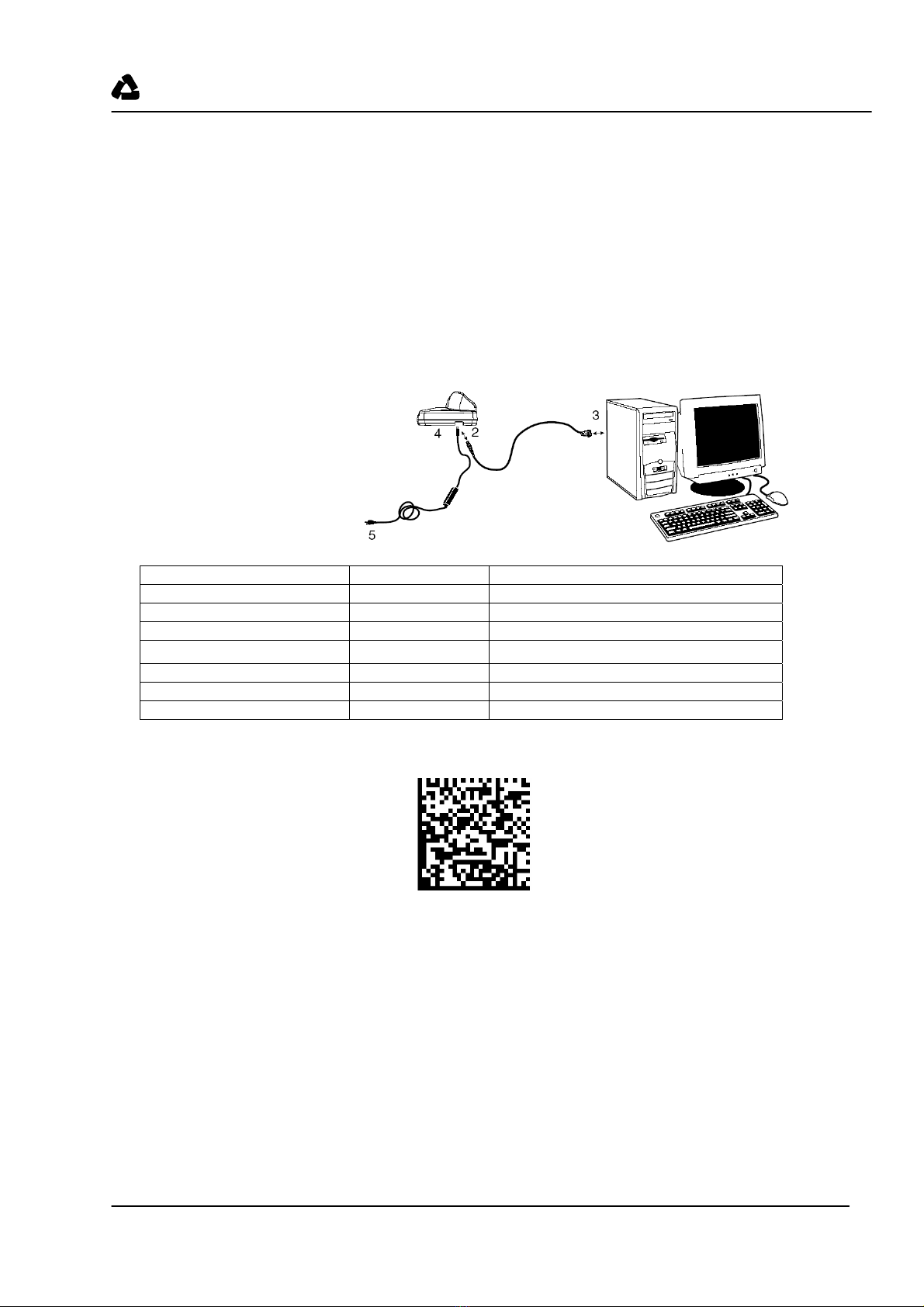
INSTALLATION ........................................................................................................................................................... 4
Switching off the computer ....................................................................................................................................... 4
CONNECTING THE BASE STATION .................................................................................................................................. 4
Connecting the cable for the ST 2020 ...................................................................................................................... 4
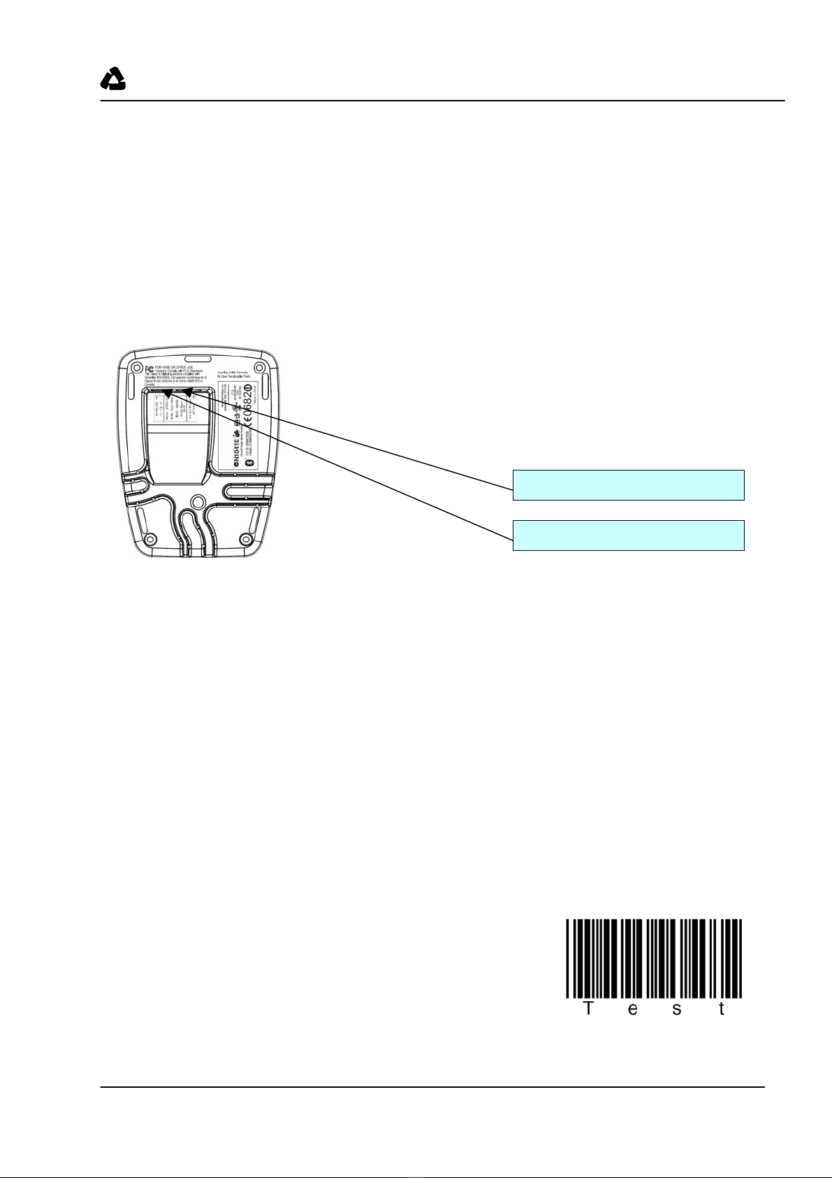
Testing the scanner................................................................................................................................................... 4
SPECIFICATIONS ........................................................................................................................................................ 5
PIN ASSIGNMENTS OF THE CONNECTION CABLE............................................................................................................. 5
TTL-RS 232 cable/PIN9 IT 4xxx Part No. 50104586 ............................................................................................. 5
PS2 cable IT 4xxx Part No. 50103409 ................................................................................................................... 5
USB cable IT 4xxx Part No. 50103404................................................................................................................... 5
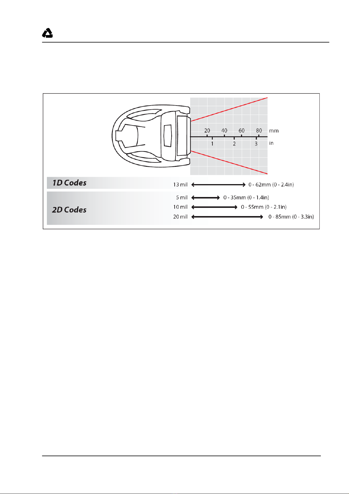
READING FIELDS ........................................................................................................................................................... 6
IT 6320 DPM............................................................................................................................................................ 6
RESETTING THE IT 6320 TO FACTORY SETTINGS ........................................................................................... 7
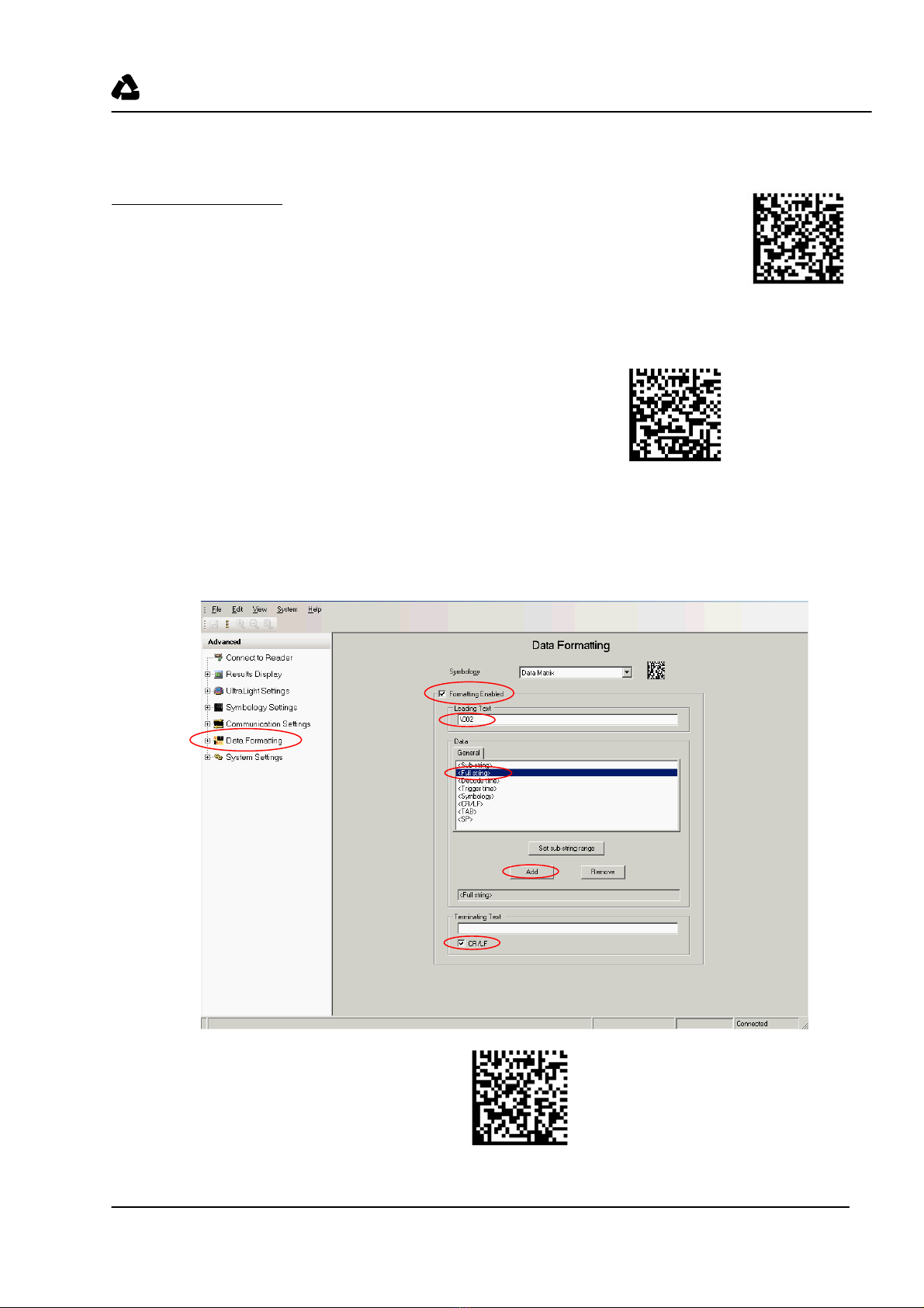
CONFIGURATION ....................................................................................................................................................... 7
IT 6320 ON THE SERIAL PC INTERFACE......................................................................................................................... 8
With TTL-RS 232 cable/PIN9 IT 4xxx Part No. 501 04586.................................................................................... 8
Configuration for the Leuze standard protocol........................................................................................................ 9
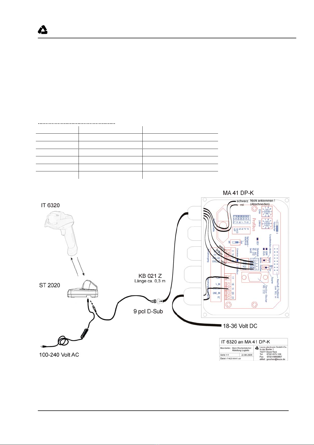
IT 6320 TO MA 21...................................................................................................................................................... 12
IT 6320 TO PS2 INTERFACE ........................................................................................................................................ 14
IT 6320 TO USB INTERFACE (KEYBOARD EMULATION) .............................................................................................. 15
IT 6320 TO USB INTERFACE (COM PORT EMULATION).............................................................................................. 16
TRIGGER...................................................................................................................................................................... 16
TROUBLESHOOTING .................................................................................................................................................... 16
TYPE OVERVIEW...................................................................................................................................................... 18
ACCESSORIES............................................................................................................................................................ 18
SPARE PARTS............................................................................................................................................................. 18
CONNECTING TO LEUZE MULTINET PLUS.................................................................................................................... 20
CONNECTING TO PROFIBUS ......................................................................................................................................... 20
CONNECTING TO INTERBUS ......................................................................................................................................... 20
CODES FOR FAST CONFIGURATION .................................................................................................................. 21