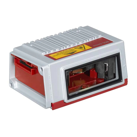
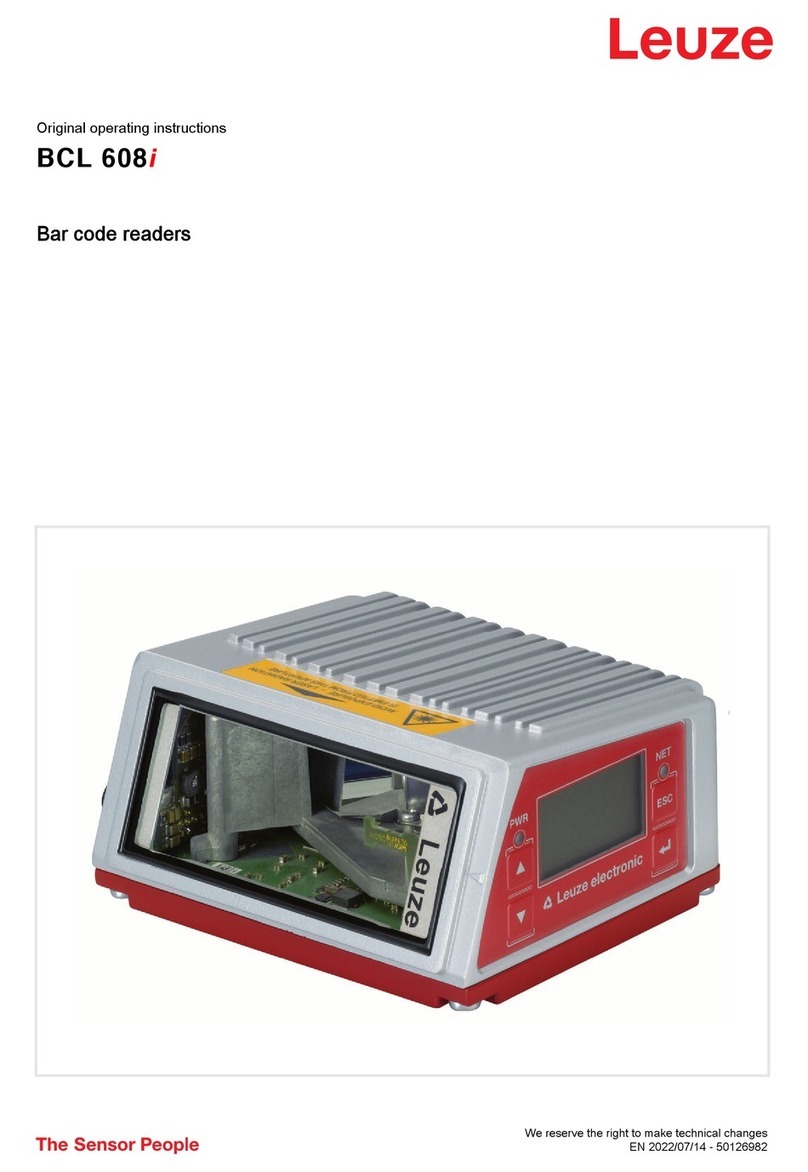
Leuze BCL 40 Parts list manual

Leuzeelectronic
Bar Code Reader BCL 40
with Integrated Decoder
Connector Unit MA 10
Technical Description

© All rights reserved, especially the right of reproduction and translation. Duplication or reproduction
in any form may only be carried out with the expressed written consent of
Leuze electronic GmbH & Co.
We reserve the right to make changes for the technical improvement of the product.

Leuze electronic BCL 40 1
Leuzeelectronic Table of contents
1 General Information...........................................................................................................5
1.1 Explanation of Symbols .......................................................................................................5
1.2 Definition of Terms...............................................................................................................5
1.3 Declaration of Conformity ....................................................................................................7
2 Safety Notices ....................................................................................................................8
2.1 Safety Standards .................................................................................................................8
2.2 Intended Use........................................................................................................................8
2.3 Working Safely.....................................................................................................................9
3 Description .......................................................................................................................10
3.1 The Bar Code Readers BCL 40.........................................................................................10
3.2 Features of the BCL 40......................................................................................................10
3.2.1 Performance features..................................................................................................................10
3.2.2 Added features with MA 10..........................................................................................................11
3.2.3 Modular Concept .........................................................................................................................11
3.3 Construction.......................................................................................................................14
3.3.1 BCL 40/device construction.........................................................................................................14
3.3.2 Device construction MA 10..........................................................................................................15
4 Specifications...................................................................................................................16
4.1 Technical Data BCL 40 Standard Version .........................................................................16
4.2 Technical Data BCL 40 with Heating .................................................................................17
4.3 Technical Data MA 10........................................................................................................18
4.4 Dimensioned drawings.......................................................................................................19
4.5 Optical Data .......................................................................................................................20
4.5.1 Type overview..............................................................................................................................21
4.5.2 Sweep principle ...........................................................................................................................21
4.5.3 Optics variants.............................................................................................................................22
4.5.4 Reading curves BCL 40 standard version...................................................................................23
4.5.5 Reading curves BCL 40 with heating...........................................................................................25
5 Accessories / Order Designation ...................................................................................27
5.1 Accessories........................................................................................................................27
5.1.1 Bar code reader BCL 40..............................................................................................................27
5.1.2 Connector and interface unit MA 10............................................................................................27
5.1.3 Mounting accessories..................................................................................................................28
5.1.4 Cable accessories .......................................................................................................................29
5.1.5 Software.......................................................................................................................................29
6 Installation........................................................................................................................30
6.1 Storage, Transportation .....................................................................................................30
6.2 Mounting ............................................................................................................................31
6.2.1 Types of Mounting.......................................................................................................................31
6.2.2 Device Arrangement....................................................................................................................34
6.3 Connection.........................................................................................................................37

2 BCL 40 Leuze electronic
Table of contents Leuzeelectronic
6.3.1 Connecting the BCL 40 for "Stand Alone" Operation...................................................................38
6.3.2 Connecting the BCL 40 with the connector unit MA 10................................................................40
6.3.3 Wire Lengths and Shielding .........................................................................................................50
6.4 Disassembling, Packing, Disposing...................................................................................50
7 Commissioning................................................................................................................51
7.1 Measures to be performed prior to the first commissioning...............................................51
7.2 Function Test.....................................................................................................................53
7.3 Setting the Parameters ......................................................................................................53
7.3.1 Parameter sets.............................................................................................................................54
7.3.2 Service Operating Mode ..............................................................................................................56
7.3.3 Setting Parameters "Offline".........................................................................................................57
7.3.4 Setting Parameters "Online".........................................................................................................58
7.3.5 Setting the Bar Code Parameters Using "autoConfig".................................................................58
8 Operation..........................................................................................................................60
8.1 Display Elements...............................................................................................................60
8.2 Important Functions During Operation...............................................................................61
8.3 Error Handling....................................................................................................................61
9 Communicating with the Device.....................................................................................62
9.1 Installation of the "BCL Configuration Tool" software........................................................62
9.2 Graphic configuration using the "BCL Configuration Tool" software..................................63
9.2.1 Code menu...................................................................................................................................64
9.2.2 Output menu ................................................................................................................................66
9.2.3 Control..........................................................................................................................................67
9.2.4 Communication ............................................................................................................................68
9.2.5 Reference code............................................................................................................................70
9.2.6 Sensor..........................................................................................................................................71
9.2.7 Switching outputs.........................................................................................................................72
9.3 Overview of Commands and Parameters..........................................................................73
9.3.1 General "Online" Commands.......................................................................................................74
9.3.2 "Online" Commands for System Control......................................................................................77
9.3.3 "Online" Commands for System Checking...................................................................................78
9.3.4 "Online" Commands for Querying Statistical Data.......................................................................80
9.3.5 "Online" Commands for Parameter Set Operations.....................................................................81
10 Maintenance .....................................................................................................................83
10.1 General Maintenance Information......................................................................................83
10.2 Repairs, Servicing..............................................................................................................83
11 Appendix...........................................................................................................................84
11.1 ASCII Table........................................................................................................................84
11.2 Example Bar Code Label Types........................................................................................88
11.2.1 Module 0.3 ...................................................................................................................................88
11.2.2 Module 0.5 ...................................................................................................................................89

Leuze electronic BCL 40 3
Leuzeelectronic Figures and tables
Figure 3.1: Possible combinations of the BCL 40 / MA 10...........................................................12
Figure 3.2: Networking possibilities using the multiNet plus.........................................................13
Figure 3.3: BCL 40/device construction........................................................................................14
Figure 3.4: Connector unit MA 10.................................................................................................15
Table 4.1: General Specifications BCL 40 Standard Version......................................................17
Table 4.2: General Specifications BCL 40 with Heater...............................................................17
Table 4.3: General Specifications MA 10....................................................................................18
Figure 4.1: Dimensioned drawing BCL 40....................................................................................19
Figure 4.2: Dimensioned drawing MA 10 .....................................................................................19
Figure 4.3: The most important characteristics of a bar code ......................................................20
Table 4.4: Type overview............................................................................................................21
Figure 4.4: Sweep principle of the raster scanner........................................................................21
Figure 4.5: Sweep principle for the line scanner ..........................................................................22
Figure 4.6: Reading curves BCL 40 standard version, optic variants N and M............................23
Figure 4.7: Reading curves BCL 40 standard version, optic variants F and L .............................24
Figure 4.8: Reading curves BCL 40 with heating, optic variants M and L....................................25
Figure 4.9: Reading curves BCL 40 with heating, optic variant F.................................................26
Table 5.1: Accessories/Order Designation BCL 40.....................................................................27
Table 5.2: Accessories/Order Designation MA 10 ......................................................................27
Figure 5.1: Mounting device BT 56...............................................................................................28
Figure 5.2: Mounting device BT 57...............................................................................................28
Figure 5.3: Connection cable between the BCL 40 and MA 10....................................................29
Figure 5.4: Connection cable between BCL 40 "stand alone"......................................................29
Figure 6.1: Device nameplates MA 10 and BCL 40 .....................................................................30
Figure 6.2: Mounting example BCL 40 "stand alone"...................................................................31
Figure 6.3: Mounting example for the combined BCL 40 / MA 10 unit.........................................32
Figure 6.4: Mounting examples for the BCL 40 and MA 10 mounted independently...................33
Figure 6.5: Minimum space requirements for installation.............................................................35
Figure 6.6: Application example "conveyor chain" .......................................................................36
Figure 6.7: Connecting the BCL 40 for "Stand Alone" Operation.................................................38
Figure 6.8: Connection diagram for the Sub D connector plug ....................................................39
Table 6.1: Wiring description BCL 40..........................................................................................40
Figure 6.9: Connecting the BCL 40 with the connector unit MA 10..............................................40
Figure 6.10: Disconnecting the ribbon cable inside the MA 10 ......................................................41
Figure 6.11: Wiring to the terminal strip without screwing down or soldering.................................42
Figure 6.12: Position of the connections for the MA 10..................................................................42
Figure 6.13: Connecting the MA 10 to a RS 485 Host ...................................................................44
Figure 6.14: Connecting the MA 10 to a RS 232 Host ...................................................................44
Figure 6.15: Connecting the MA 10 as active subscriber to a TTY Host........................................45
Figure 6.16: Connecting the MA 10 as passive subscriber to a TTY Host.....................................45
Figure 6.17: Connecting the MA 10 to a RS 422 Host ...................................................................46
Figure 6.18: Connection of the switching input with an external switching voltage........................47
Figure 6.19: Connection of the switching input without an external switching voltage...................47
Figure 6.20: Position of the solder jumpers JL5 and JL6 ...............................................................48
Figure 6.21: Operating voltage used as the switching voltage.......................................................49
Figure 6.22: Switching voltage connected externally (galvanically decoupled)..............................49
Figure 7.1: Control elements of the MA 10...................................................................................51
Figure 7.2: Block diagram storage concept for parameter sets....................................................55
4 BCL 40 Leuze electronic
Figures and tables Leuzeelectronic
Figure 7.3: Connecting the service interface to a PC or terminal.................................................56
Figure 9.1: Installation window.....................................................................................................62
Figure 9.2: Installation directory...................................................................................................63
Figure 9.3: "Decode" menu, standard setting...............................................................................64
Figure 9.4: Properties of the Decode menu, standard setting......................................................65
Figure 9.5: "Output" menu............................................................................................................66
Figure 9.6: "Control" menu, standard setting................................................................................67
Figure 9.7: "Communication" menu, standard setting..................................................................68
Figure 9.8: Properties of the Communication menu, standard setting .........................................69
Figure 9.9: "Reference code" menu .............................................................................................70
Figure 9.10: "Sensor" menu, standard setting................................................................................71
Figure 9.11: "Switch 1" menu, standard setting..............................................................................72
Table 11.1: ASCII Table................................................................................................................87
Figure 11.1: Bar code sample labels (module width 0.3) ...............................................................88
Figure 11.2: Bar code sample labels (module 0.5).........................................................................89

Leuzeelectronic General Information
Leuze electronic BCL 40 5
TNT 35/7-24V
1 General Information
1.1 Explanation of Symbols
The symbols used in this operating manual are explained below.
Attention!
Pay attention to passages marked with this symbol. Failure to heed this information can lead
to injuries to personnel or damage to the equipment.
Attention Laser!
This symbol warns of possible danger through hazardous laser radiation.
Notice!
This symbol indicates text passages containing important information.
1.2 Definition of Terms
Activation
Initiates a read process, e.g. by triggering the switched input.
ASCII
Standard character set (American Standard Code for Information Interchange) with 128
characters. Each character of the ASCII character set has been assigned a number from 0
to 127. This number is usually displayed in decimal format, but can also be displayed in hex-
adecimal or octal.
autoConfig
The function integrated into the bar code reader which automatically recognises the type
and number of characters of the code to be read in.
autoControl
The function integrated into the bar code reader used to monitor the read quality.
Bar code
An arrangement of parallel bars and spaces which are arranged according to a standardised
protocol such that they have a certain numeric or alphanumeric meaning.
Deactivation
End a read process, e.g. by using an online command.
Decoder/Decoding system
The microprocessor control unit which translates the scanned bar code information into a
simple signal that can be processed further.
Frame protocol
Transfer protocol for the data transfer between the bar code reader and the host.

General Information Leuzeelectronic
6 BCL 40 Leuze electronic
Hex.
Abbreviation for hexadecimal notation.
Host
External computer or programmable logic controller (PLC) which is connected to the bar
code reader via a serial interface and is used to further process the decoded bar code infor-
mation.
Interface module
Electronic component in the connector unit MA 10 which carries out the electrical adjust-
ment of the various serial interface types (e.g. RS 232, RS 422, etc.).
Label
Barcode label
multiNet
The network developed by Leuze for networking together several bar code readers.
No Read
Read failure; a read process was initiated but a label could not be decoded.
Online command
A command which is sent directly to the bar code reader from the host or a computer
connected to the interface.
Output format
Determines the data format of the bar code information output from the decoder.
Parameter set
The data set which is permanently stored in the bar code reader and contains all of the
device settings.
PD
Programming device
PLC
Programmable logic controller. A PLC usually can be used as a host.
Postfix
Trailer of the data transfer protocol (frame protocol) between the bar code reader and the
host.
Prefix
Header of the data transfer protocol (frame protocol) between the bar code reader and the
host.
Protocol
Interface protocol of the serial interface.
Raster scanner
The sweep method of the scanner laser beam. It is used when the lines of the bar code can
only be applied vertically with respect to the direction of travel, or when the code must be
read while stationary.
Read quality
The read quality can be monitored using the autoControl function. The relationship of the
number of successful reads to the total number of reads is determined and monitored.

Leuzeelectronic General Information
Leuze electronic BCL 40 7
TNT 35/7-24V
Reference code
Complete or partial bar code information which can be compared to the read label, e.g. to
select a path for packages.
Scanner
Bar code reader that optically scans the bar code with a laser beam.
Switched input
Bipolar input for connecting a sensor or switch used for initiating a read process or for
acquiring a reference code.
Switched output
Connection for output of status or event messages, e.g. after a failed read.
Teach-In
Programming a reference code using an example bar code.
1.3 Declaration of Conformity
The bar code readers BCL 40 and the connector unit MA 10 have been developed and
produced in accordance with the applicable European standards and directives.
Notice!
The corresponding declaration of conformity can be requested from the manufacturer.
The manufacturer of the product, Leuze electronic GmbH & Co. in D-73277 Owen/Teck,
possesses a certified quality assurance system in accordance with ISO 9001.

Safety Notices Leuzeelectronic
8 BCL 40 Leuze electronic
2 Safety Notices
2.1 Safety Standards
The bar code readers BCL 40 and the connector unit MA 10 have been developed, produced
and tested subject to the applicable safetystandards. They correspond to the state of theart.
2.2 Intended Use
Attention!
The protection of personnel and the device cannot be guaranteed if the device is operated
in a manner not corresponding to its intended use.
Bar code readers of the type BCL 40 are conceived as stationary, high-speed scanners with
integrated decoders for all current bar codes used for automatic object recognition.
The connector and interface unit MA 10 simplifies the connection of the bar code reader of
type BCL 40 and adapts to various host interfaces. Connection to other bar code readers is
not authorised.
In particular, unauthorised use includes:
• rooms with explosive atmospheres
• operation for medical purposes
Fields of application
The bar code readers BCL 40 with optional connector unit MA 10 are conceived particularly
for the following fields of application:
• labelling and packaging machines
• automatic analysers
• space-critical bar code reading tasks
• storage and conveying technologies, in particular for object identification on
fast-moving conveyor belts
• pharmaceutical industry

Leuzeelectronic Safety Notices
Leuze electronic BCL 40 9
TNT 35/7-24V
2.3 Working Safely
Attention Laser Radiation!
The BCL 40 are laser devices of the Laser Protection Class 2.
Do not look directly into the laser beam. Observe the applicable legal and local regulations
for the operation of laser units.
Attention!
Access to or changes on the device, except where expressly described in this operating
manual, is not authorised.
Safety Regulations
Observe the locally applicable legal regulations and the rules of the employer’s liability insur-
ance association.
Qualified Personnel
Mounting, commissioning and maintenance of the device must only be carried out by qual-
ified personnel.
Electrical work must be carried out by a certified electrician.

Description Leuzeelectronic
10 BCL 40 Leuze electronic
3 Description
3.1 The Bar Code Readers BCL 40
The bar code reader BCL 40 is a high-speed scanner with integrated decoder for all bar
codes currently in use, e.g. 2/5 Interleaved, EAN, etc.
The many possible configurations of the device allow its adaptation to a multitude of reading
tasks. Due to its compact size and short minimum reading distance, the BCL 40 can also be
used in very compact spaces.
Together with the connector unit MA 10, it can easily be adapted for use with various inter-
faces, thus allowing additional processing by other systems. The MA 10 connector unit can
also be used to network together several BCL 40 devices and to simplify electrical installa-
tion.
On demand, the BCL 40 can be equipped with an integrated heater. This variant is used
primarily in low-temperature and outdoor applications. The optional heater is constructed
such that no heat transfer occurs between the separately mounted technical unit and the
scanner housing. In addition, the front cover of the device is heated, preventing the forma-
tion of condensation which would affect the reading function. The reading curves differ with
respect to the standard type in the construction of the front cover, which is modified by
heating filaments.
3.2 Features of the BCL 40
3.2.1 Performance features
• Compact device dimensions (W x H x D) 90 x 120 x 43mm
• Reading height of 70 mm at a distance of 10mm
• Maximum reading distance up to 700mm (depending on type of optics)
• Raster or line scanner (R1 = raster, S = single line) max. 1200scans/s
• A switched input for triggering a read process using sensors
• Automatic monitoring of the read quality with the "autoControl" function
• Automatic recognition of the bar code type using "autoConfig"
• All device parameters can be set by software
• Heavy-duty housing of protection class IP 65 with corresponding cable
• RS 232 or RS 485 interface to host
• Extensive formatting possibilities for data output
• Reference code (comparison code)

Leuzeelectronic Description
Leuze electronic BCL 40 11
TNT 35/7-24V
3.2.2 Added features with MA 10
• Device status display with 4 LEDs
• RS 485 interface with electrical isolation for networking several devices
• Alternative interface RS 232, RS 422 or TTY using a selectable interface module with
electrical isolation for directly connecting to the host
• Two hardware switched outputs for status signals
• Additional switched input for the definition of reference code 1
• Simple electrical connection via double terminal clamps, i.e. both the power supply
and the interface circuits can easily be connected in series.
• Heavy-duty housing of protection class IP 65
• 2 parameter sets can be stored locally in the MA 10
(current parameter set, customer-specific parameter set)
• Built-in RS 232 service interface for fast commissioning or troubleshooting on site
using a PC or programming device
• Switch for the "autoConfig" function
3.2.3 Modular Concept
BCL 40 "Stand alone"
The bar code reader BCL 40 can be operated as an individual "stand alone" () device.
Electrical connection of the power supply, interface and switched input are centrally made
via a 15 pin SubD socket.
For connection, it is best to use the 15 conductor connection cable from Leuze. The require-
ments for protection class IP 65 are fulfilled when using this cable only (see chapter 5
"Accessories / Order Designation").
BCL 40 with MA 10
When using several BCL 40 units or under rough environment conditions, the installation of
one connector unit MA 10 for each BCL 40 unit is recommended.
Electrical connection, commissioning, and service can be comfortably carried out in a short
period of time.
The BCL 40 and MA 10 can be mounted directly together (ó) or arranged separately next
to each other. When mounted separately (ì), the two units are connected by a cable.
Protection class IP 65 is maintained when the sealed accessory cable is used (see chapter
5 "Accessories / Order Designation").

Description Leuzeelectronic
12 BCL 40 Leuze electronic
Figure 3.1: Possible combinations of the BCL 40 / MA 10
Networking
Up to 31 BCL 40 bar code readers can be networked together using the connector unit
MA 10 (with interface module RS 485). The devices are interconnected by connecting the
individual RS 485 interfaces in parallel.
multiNet plus
In the Leuze multiNet plus, the individual network devices sequentially transfer their data to
the network master MA 30 when requested ("polling").
The master station can also be fitted with an BCL 40, making it a complete scanner station
which also controls the network.
Each network device declared as a slave maintains a device address which is set in the
respective MA 10 with a coding switch. If the reader unit is exchanged (BCL), the device
address and all settings in the MA 10 are maintained.
The master then transmits the data of all network devices via its host interface to a primary
PLC control system or a computer, i.e. it "collects" thescanner data in the network and trans-
mits them to an interface on the host computer. This reduces interface costs (CPs) and time
programming the software.
The MA 30/31 are suitable for use as network master devices.
BCL 40 as
"Stand alone"-device
ó
BCL 40 with the
connectorunitMA 10
mounted together
ì
BCL 40 and MA 10
mounted separately
and connected
together by a cable

Leuzeelectronic Description
Leuze electronic BCL 40 13
TNT 35/7-24V
Figure 3.2: Networking possibilities using the multiNet plus
Two-wire RS 485
The Leuze MultiNet plus is optimised for fast transmission of scanner data to a primary host
computer. The multiNet plus physically consists of a two-wire RS 485 interface through
which the multiNet plus software protocol is controlled. Thus network connection is very
simple and inexpensive: the network connection is simply passed through to the next slave.
Interface modules
Shielded, twisted pair conductors should be used for the multiNet. This allows a total
network length of up to 1200m.
Connection of the network to the primary computer is made via the host interface of the MA
30 which can be equipped with 4 different physical interface modules. Modules for RS 232,
RS 422, TTY and RS 485 are available.
Slave
MA 10
Slave
MA 10
Slave
MA 10
RS 232
RS 422
RS 485 or
TTY -Backup
parameters
Voltage
supply
Network master
multiNet plus
MA 30
RS 485
Sensor
Sensor
Sensor
Sensor

Description Leuzeelectronic
14 BCL 40 Leuze electronic
3.3 Construction
3.3.1 BCL 40/device construction
Figure 3.3: BCL 40/device construction
Reading
window
4 fastening threads M4 on the
rear of the device
15-pin sub-D
connector on the
underside of the
unit
Dovetail fastening
grooves

Leuzeelectronic Description
Leuze electronic BCL 40 15
TNT 35/7-24V
3.3.2 Device construction MA 10
Figure 3.4: Connector unit MA 10
Device variations MA 10
The MA 10 is available in four models:
• MA 10 100 with host interface module RS 485
• MA 10 110 with host interface module RS 232
• MA 10 120 with host interface module TTY
• MA 10 130 with host interface module RS 422
All modules are galvanically isolated, i.e. they are EMC interference protected and immune
to differences in voltage potentials across long cable lengths.
Notice!
Only the type MA 10 100 can be used as a multiNet slave unit.
Cable screw glands PG11
for the power supply
Cable screw glands PG11
for the power supply
4 fastening threads M4 on the
base of the device
4 Status-LEDs
on the rear
Mountingholesforthe
BCL 40 with M4
screws
15 pin Sub-D
connector
Dovetail fastening
grooves

Specifications Leuzeelectronic
16 BCL 40 Leuze electronic
4 Specifications
4.1 Technical Data BCL 40 Standard Version
Optical Data
Light source Laser diode 650nm
Scanning rate BCL with N, M, F optics: 1200scans/s
BCL with L optics: 900scans/s
Resolution 0.1mm … 1.2mm
module width
Beam deflection by means of rotating polygon mirror wheel
Reading distance 0 … 700mm (depending on type of optics: N, M, F, L), see
chapter 4.5.4 "Reading curves BCL 40 standard version"
Reading field opening 70mm at a distance of approx. 10mm (see chapter 4.5.4
"Reading curves BCL 40 standard version")
Grid (R1) 8 lines
Grid field specified is the area from the first to the last laser beam as
a function of distance to the scanner
22mm at 100mm scanner distance
33mm at 200mm scanner distance
45mm at 300mm scanner distance
65mm at 500mm scanner distance
95mm at 800mm scanner distance
Single line (S) 1 line
Optical window glass with scratch-resistant Indium coating
Laser safety class 2
Code types 2/5 Interleaved; Code 39; Code 128; EAN 8; 13; EAN 128;
UPC; Codabar; Add-On for EAN / UPC
Software features selectable output format, autoConfig, autoControl, refer-
ence code comparison, multiple read, real time decoding,
adjustment mode, diagnosis, reading gate control, control
of switching inputs and switching outputs, etc.
Electrical data
Interface type can be switched between RS 232 and RS 485, additional
service interface (RS 232)
TTY / RS 422 optional with MA 10
Baud rate 110 … 57600Bd (host interface only)
Data formats data bits: 7, 8, 9
parity: None, Even, Odd
Stop bit: 1, 2
Protocols with/without frame protocol
ACK/NAK, 3964 (R) RK 512, RTS/CTS
X ON / X OFF, multiNet plus
Ports 1 switching input
LED green device ready (Power On)

Leuzeelectronic Specifications
Leuze electronic BCL 40 17
TNT 35/7-24V
Table 4.1: General Specifications BCL 40 Standard Version
4.2 Technical Data BCL 40 with Heating
The following table is limited to the data which are different than those specified for the
standard model.
Table 4.2: General Specifications BCL 40 with Heater
Switching input 12 … 36VDC/AC voltage, selectable galvanic isolation or
supplied operating voltage, max. insulation voltage: 250V
(with galvanic isolation)
Operating voltage 18 … 36V
Power consumption 5VA max.
Mechanical data
Protection class IP 65
Weight approx. 430g
Dimensions (WxHxD) 120 x 90 x 43mm
Housing diecast aluminium
Environmental data
Ambient temperature
(operation/storage) 0°C …+40°C /-20°C …+60°C
Air humidity max. 90% rel. humidity, non-condensing
Vibration IEC 68.2.6
Shock IEC 68.2.27
EMC IEC 801
Optical Data
Light source Laser diode 660nm
Resolution 0.25mm … 1.0mm module width
Reading distance 0 … 630mm (depending on type of optics: M, F, L)
see chapter 4.5.5 "Reading curves BCL 40 with heating"
Reading field opening Depending on the distance, the reading curve is typically
approx. 20 … 70mm narrower see chapter 4.5.5 "Reading
curves BCL 40 with heating"
Electrical data
Operating voltage 24VDC ± 2V
Power consumption 10W max.
Mechanical data
Weight approx. 500g
Dimensions (WxHxD) 120 x 90 x 52mm
Environmental data
Ambient temperature
(operation/storage) -40°C … +30°C/-20°C … +60°C

Specifications Leuzeelectronic
18 BCL 40 Leuze electronic
4.3 Technical Data MA 10
Table 4.3: General Specifications MA 10
Mechanical data
Housing Diecast aluminium
Dimensions (WxHxD) 130 x 90 x 78mm
Weight approx. 740g
Protection class IP 65
Interfaces
Type (optional) RS 232, with galvanic isolation
RS 422, with galvanic isolation
RS 485, with galvanic isolation
TTY, with galvanic isolation
Service interface RS 232 internal, 9 pin Sub D plug, male
Inputs/outputs
2 switched inputs galvanically isolated,with supply voltage terminal for sen-
sors 12 … 36VDC/AC, insulation voltage 500V
2 switched outputs can be operated galvanically isolated or not isolated
switching voltage 5 … 48VDC, max. load 500mA
Power supply
Operating voltage 18 … 36VDC
Power consumption 2VA max.
Environmental data
Ambient temperature
(operation/storage) 0°C … +50°C/-20°C … +60°C
Air humidity max. 90% rel. humidity, non-condensing
Vibration IEC 68.2.6
Shock IEC 68.2.27
EMC IEC 801
Table of contents
Other Leuze Barcode Reader manuals

Leuze
Leuze IT 3800g User manual

Leuze
Leuze BPS 338i User manual

Leuze
Leuze BPS 8 User manual

Leuze
Leuze BPS 34 User manual

Leuze
Leuze BPS 3048i User manual

Leuze
Leuze IT 6320 DPM Setup guide

Leuze
Leuze it 1452g User manual

Leuze
Leuze DCR 258i User manual

Leuze
Leuze BCL 208i User manual

Leuze
Leuze BPS 348i User manual

Leuze
Leuze BPS 3007i User manual

Leuze
Leuze BCL604i User manual

Leuze
Leuze BCL 8 User manual

Leuze
Leuze BCL34 Parts list manual

Leuze
Leuze BCL 648i User manual

Leuze
Leuze CR 100 User manual

Leuze
Leuze BCL 300i User manual

Leuze
Leuze BCL 608i SM 102 User manual

Leuze
Leuze HS 6508 User manual

Leuze
Leuze BCL 308i User manual