LGB 26605 User manual

Modell der RhB Schneeschleuder
26605

2
!

3
Inhaltsverzeichnis: Seite
Sicherheitshinweise 4
Wichtige Hinweise 4
Funktionen 4
Betriebshinweise 4
Multiprotokollbetrieb 5
Wartung und Instandhaltung 6
Schaltbare Funktionen 7
Wartung und Instandhaltung 7
CV -Tabelle 8
Tabelle Funktionsmapping DCC 40
Bilder 42
Ersatzteile 45
Table of Contents: Page
Safety Notes 10
Important Notes 10
Functions 10
Information about operation 10
Multi-Protocol Operation 11
Controllable Functions 13
Service and maintenance 13
Table for CV 14
Table for Function Mapping DCC 40
Figures 42
Spare parts 45
Inhoudsopgave: Pagina
Veiligheidsvoorschriften 22
Belangrijke aanwijzing 22
Functies 22
Bedrijfsaanwijzingen 22
Multiprotocolbedrijf 23
Schakelbare functies 25
Onderhoud en handhaving 25
CV 26
Tabel functiemapping DCC 40
Afbeeldingen 42
Onderdelen 45
Indice del contenuto: Pagina
Avvertenze per la sicurezza 34
Avvertenze importanti 34
Funzioni 34
Avvertenze per ilfunzionamento 34
Esercizio multi-protocollo 35
Funzioni commutabili 37
Manutenzione ed assistere 37
CV 38
Tabella di mappatura delle Funzioni DCC 40
Figures 42
Pezzi di ricambio 45
Sommaire : Page
Remarques importantes sur la sécurité 16
Information importante 16
Fonctionnement 16
Remarques sur l’exploitation 16
Mode multiprotocole 17
Fonctions commutables 19
Entretien et maintien 19
CV 20
Tableau pour mapping des fonctions DCC 40
Images 42
Pièces de rechange 45
Indice de contenido: Página
Aviso de seguridad 28
Notas importantes 28
Funciones 28
Instrucciones de uso 28
Funcionamiento multiprotocolo 29
Funciones commutables 31
El mantenimiento 31
CV 32
Tabla de mapeado de funciones DCC 40
Figuras 42
Recambios 45

4
Sicherheitshinweise
• DasModelldarfnurmiteinemdafürbestimmten
Betriebssystem eingesetzt werden.
• NurSchaltnetzteileundTransformatorenverwenden,
die Ihrer örtlichen Netzspannung entsprechen.
• DasModelldarfnurauseinerLeistungsquelleversorgtwerden.
• BeachtenSieunbedingtdieSicherheitshinweiseinderBedienungsanleitungzu
Ihrem Betriebssystem.
• NichtfürKinderunter15Jahren.
• ACHTUNG!FunktionsbedingtescharfeKantenundSpitzen.
• VerbauteLED`sentsprechenderLaserklasse1nachNormEN60825-1.
•
Dieses Produkt enthält Magnete. Das Verschlucken von mehr als einem Magneten
kann unter Umständen tödlich wirken. Gegebenenfalls ist sofort ein Arzt aufzusuchen.
Wichtige Hinweise
• DieBedienungsanleitungistBestandteildesProduktesundmussdeshalbaufbe-
wahrt sowie bei Weitergabe des Produktes mitgegeben werden.
• GewährleistungundGarantiegemäßderbeiliegendenGarantieurkunde.
• FürReparaturenoderErsatzteilewendenSiesichbitteanIhrenLGB-Fachhändler.
• Entsorgung:www.maerklin.com/en/imprint.html
• AufgrunderbesonderenOberächedesGehäusesundeinigerAnbauteileist
besondereVorsichtimUmgangmitderLokerforderlich.AufdenglänzendenTeilen
könnensichFingerabdrückeabzeichnen.BittebeachtenSie,dasszurReinigung
keineLösungsmittelodergrobeTücherverwendetwerdendürfen.Beschädigte
EinzelteilekönnenüberdenMärklinReparaturservicegetauschtwerden.
Funktionen
• DasModellistfürdenBetriebaufLGB-Zweileiter-Gleichstrom-Systemenmit
herkömmlichenLGB-Gleichstrom-Fahrpultenvorgesehen(DC,0–24V).
• WerkseitigeingebauterMultiprotokoll-Decoder(DC,DCC,mfx).
• ZumEinsatzmitdemLGB-Mehrzugsystem(DCC)istdasModellaufLokadresse03
programmiert.ImBetriebmitmfxwirddieLokautomatischerkannt.
• Mfx-TechnologiefürMobileStation/CentralStation.
NameabWerk:Xrot 9213
• DieFunktionenkönnennurparallelaufgerufenwerden.DieseriealleFunktionsaus-
lösungistnichtmöglich(beachtenSiehierzudieAnleitungzuIhremSteuergerät).
Allgemeiner Hinweis zur Vermeidung elektromagnetischer Störungen:
UmdenbestimmungsgemäßenBetriebzugewährleisten,isteinpermanenter,
einwandfreierRad-Schiene-KontaktderFahrzeugeerforderlich.FührenSiekeine
VeränderungenanstromführendenTeilendurch.
Hinweise
• DasModellmussvordemerstenBetriebgeschmiertwerden
• WenndasModellmitaktivemDampfgeneratorbetriebenwird,sokanninsBeson-
derederdurchdieZylinderausströmendeDampfdieGleisestarkverschmutzen.
• DiesesModellisthinsichtlichderTechnikunderAusführungbesondersaufwän-
dig und hochwertig. Die meisten angesteckten oder verbauten Teile sind aus
Metallgefertigt.SolcheTeilekönnennichtsoeinfachgetauschtwerden,wie
z.B.Kunststoffteile.BittebeachtenSiedaher,dassSiediesesModellbesonders
vorsichtig handhaben sollten.
Betriebsartenschalter
InderSchneeschleuderistein2-stugerBetriebsartenschalter(Bild1).
Pos. 0 Schneeschleuder stromlos abgestellt
Pos. 1 alles an
Rauchgenerator
In der Schneeschleuder ist ein radsynchroner Rauchgenerator eingebaut. Wegen
derhohenLeistungsaufnahmekannerfürdenAnalogbetriebübereinenSchalter
ausgeschaltetwerden(Bild1).
DasRauchöl(Märklin02421)wirdüberdenDampfschlotnachgefüllt(max.10ml
einfüllen).WirddieSchneeschleudermitgefülltemDampfgeneratorgekippt,soläuft
dasDampfölübereinenÜberlaufdurchdieZylinderwiederaus.
Schneeschleuder
Die Drehrichtung des Schleuderrades ist im Digigalbetrieb umschaltbar.
AusSicherheitsgründenistdieDrehkraftamSchleuderradreduziert.DieSchnee-
schleuderistnichtfürdenpraktischenEinsatzimSchneegeeignet.
(DieSchneeschleuderkannnichtzumwirklichenSchneeräumeneingesetztwerden.)
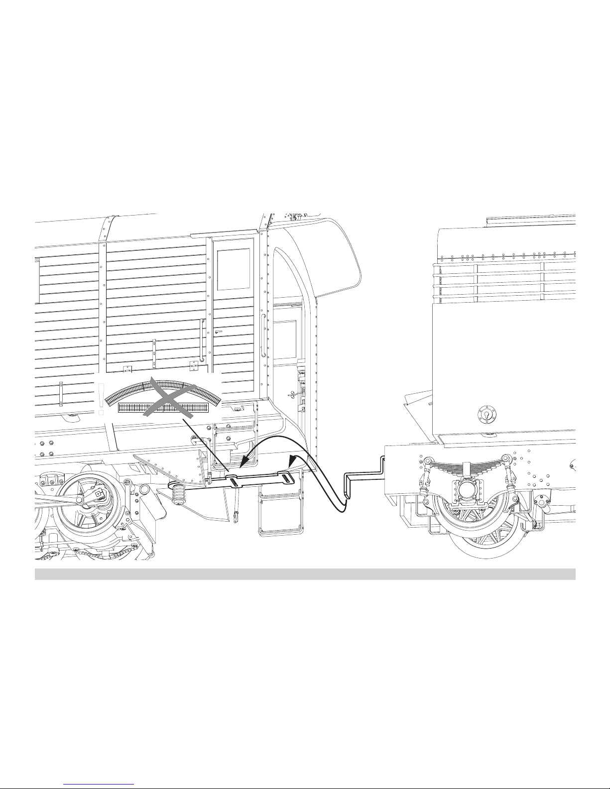
VordemSchleuderradsindlinksundrechtsKlappenangeordnet,diefürdenBetrieb
geöffnetundmitbeiliegendenStangenxiertwerdenkönnen(Bild2&3).
BeachtenSie,dassdieSchneeschleudermitgeöffnetenKlappendasLichtraumprol
aufdemGleisüberschreitet.
Elektronischer Sound
DiePfeifekannauchmitdemLGB-Sound-Schaltmagneten(17050)ausgelöstwerden.
DerSchaltmagnetlässtsichzwischendieSchwellendermeistenLGB-Gleiseklipsen.
PlatzierenSiedenMagnetenmitdemLogoaufderrechtenbzw.linkenSeitedes
Gleises,umdiePfeifekurz/langauszulösen,wenndasModelldieseStelleüber-
quert.

5
Multiprotokollbetrieb
Analogbetrieb
Der Decoder kann auch auf analogen Anlagen oder Gleisabschnitten betrieben wer-
den.DerDecodererkenntdieanalogeGleichspannung(DC)automatischundpasst
sichderanalogenGleisspannungan.EssindalleFunktionen,dieuntermfxoderDCC
fürdenAnalogbetriebeingestelltwurdenaktiv(sieheDigitalbetrieb).
Die Eingebauten Sound-Funktionen sind ab Werk im Analogbetrieb nicht aktiv.
Digitalbetrieb
Der Decoder ist ein Multiprotokolldecoder. Der Decoder kann unter folgenden Digital-
Protokolleneingesetztwerden:mfxoderDCC.
Das Digital-Protokoll mit den meisten Möglichkeiten ist das höchstwertige Digital-
Protokoll.DieReihenfolgederDigital-ProtokolleistinderWertungfallend:
Priorität1:mfx;Priorität2:DCC;Priorität3:DC
Hinweis:Digital-Protokollekönnensichgegenseitigbeeinussen.Füreinenstö-
rungsfreienBetriebempfehlenwir,nichtbenötigteDigital-ProtokollemitCongura-
tionsVariable(CV)50zudeaktivieren.
DeaktivierenSie,soferndiesIhreZentraleunterstützt,auchdortdienichtbenötigten
Digital-Protokolle.
WerdenzweiodermehrereDigital-ProtokolleamGleiserkannt,übernimmtderDe-
coderautomatischdashöchstwertigeDigital-Protokoll,z.B.mfx/DCC,somitwirddas
mfx-Digital-ProtokollvomDecoderübernommen.
Hinweis:BeachtenSie,dassnichtalleFunktioneninallenDigital-Protokollenmöglich
sind.UntermfxundDCCkönneneinigeEinstellungenvonFunktionen,welcheim
Analog-Betriebwirksamseinsollen,vorgenommenwerden.
Hinweise zum Digitalbetrieb
• DiegenaueVorgehensweisezumEinstellenderdiversenCVsentnehmenSiebitte
derBedienungsanleitungIhrerMehrzug-Zentrale.
• DieabWerkeingestelltenWertesindfürmfxgewählt,sodasseinbestmöglichstes
Fahrverhalten gewährleistet ist.
FürandereBetriebssystememüssengegebenenfallsAnpassungengetätigt
werden.
mfx-Protokoll
Adressierung
• KeineAdresseerforderlich,jederDecodererhälteineeinmaligeundeindeutige
Kennung(UID).
• DerDecodermeldetsichaneinerCentralStationoderMobileStationmitseiner
UID-Kennungautomatischan.
Programmierung
• DieEigenschaftenkönnenüberdiegrascheOberächederCentralStationbzw.
teilweise auch mit der Mobile Station programmiert werden.
• EskönnenalleCVmehrfachgelesenundprogrammiertwerden.
• DieProgrammierungkannentwederaufdemHaupt-oderdemProgrammiergleis
erfolgen.
• DieDefaulteinstellungen(Werkseinstellungen)könnenwiederhergestelltwerden.
• Funktionsmapping:FunktionenkönnenmitHilfederCentralStation60212(einge-
schränkt)undmitderCentralStation60213/60214/60215beliebigenFunktionstasten
zugeordnetwerden(SieheHilfeinderCentralStation).
DCC-Protokoll
Adressierung
• KurzeAdresse–LangeAdresse–Traktionsadresse
• Adressbereich:
1-127kurzeAdresse,Traktionsadresse
1 - 10239 lange Adresse
• JedeAdresseistmanuellprogrammierbar.
• KurzeoderlangeAdressewirdüberdieCV29ausgewählt.
• EineangewandteTraktionsadressedeaktiviertdieStandard-Adresse.
• AbWerkistderDecoderauf28eingestellt.FürältereSystememussgegebenen-
fallsauf14Fahrstufenumgestelltwerden(CV29).
Programmierung
• DieEigenschaftenkönnenüberdieCongurationVariablen(CV)mehrfachgeän-
dert werden.
• DieCV-NummerunddieCV-Wertewerdendirekteingegeben.
• DieCVskönnenmehrfachgelesenundprogrammiertwerden(Programmierung
aufdemProgrammiergleis).
• DieCVskönnenbeliebigprogrammiertwerden(PoM-Programmierungaufdem
Hauptgleis).PoMistnichtmöglichbeidenCV1,17,18und29.PoMmussvonIhrer
Zentraleunterstütztwerden(sieheBedienungsanleitungihresGerätes).
• DieDefaulteinstellungen(Werkseinstellungen)könnenwiederhergestelltwerden.
• 14bzw.28/128Fahrstufeneinstellbar.
• AlleFunktionenkönnenentsprechenddemFunktionsmappinggeschaltetwerden.
• WeitereInformation,sieheCV-TabelleDCC-Protokoll.
Eswirdempfohlen,dieProgrammierungengrundsätzlichaufdemProgrammiergleis
vorzunehmen.

6
Funktionsmapping DCC
Esistmöglich,dieFunktionalitäten,dievomDecodergesteuertwerden,denFunkti-
onstastennachWunschzuzuordnen(mappen).DazumussinderentsprechendenCV
ein entsprechender Wert eingetragen werden.
InderTabelleaufdenSeiten42/43sinddieCVs(Zeilen)unddieFunktionalitäten
(Spalten)aufgeführt.ZujederTastegehören4CVs.AusPlatzgründenwurdenabCV
282(TasteF5)die4CVszujederTastejeweilsineinerZeilezusammengefasst.
Grundsätzlichistesmöglich,einerTastemehrereFunktionalitäten,bzw.eineFunktio-
nalität mehreren Tasten zuzuweisen.
Hinweis: Die Programmierung des Funktionsmappings sollte nur durch erfahrene
Anwenderdurchgeführtwerden.
JenachAuslegungdesDecoderskönneneinzelneFunktionalitätenüberSUSI
gesteuert sein. Diese Funktionalitäten werden vom Decoder als Sound behandelt. Die
zugehörigenLautstärkenkönnendannnicht verändert werden.
Beispiele zum Funktionsmapping:
AUX2sollvorwärtsundrückwärtsaufFunktion3
CV272&CV372=8
CV273&CV373=0
CV274&CV374=0
CV275&CV375=0
Sound15sollvonvorwärtsundrückwärtsFunktion3aufFunktion8verlegtwerden.
DiebestehendeBelegungvonFunkton8wirddabeiüberschrieben.
CV275&CV375=0
CV273&CV373=0
CV274&CV374=0
CV275&CV375=0
CV297&CV397=0
CV298&CV398=0
CV299&CV399=0
CV300&CV400=4
hin zu Funktion 8
weg von Funktion 3
vorwärts
rückwärts

7
Schaltbare Funktionen
Spitzensignal 1LV+LR
Geräusch:Pfeife 1 Sound 1
Geräusch:Bremsenquietschenaus 2 BS
Schleudermaschine Rechtslauf mit Geräusch 3 Sound 7
+AUX3
SchleudermaschineLinkslaufmitGeräusch 4
Sound 7
+AUX4
Geräusch:Kohleschaufeln 5 Sound 9
Geräusch:Betriebsgeräusch1,2 6 FS
Rauchgenerator 7 Sound4+
Sound8+
Sound 15
Soundan/aus 8 Sound 12
ABV,aus 9
Führerstandsbeleuchtung 10 AUX1+
AUX 2
Geräusch:Pfeifekurz 11 Sound 2
Geräusch:Ansage+Pfeife 12 Sound 16
Geräusch:Ansage 13 Sound 14
Geräusch:Ansage 14 Sound 6
Geräusch:Ansage 15 Sound 5
1im Analogbetrieb aktiv
2 mitZufallsgeräuschen
Hinweis:
Unterwww.LGB.dendenSieunter„ToolsundDownloads“eineausführliche
BeschreibungdesDecoderssowieeinTool,mitdemSieverschiedeneEinstellungen
berechnen können.
WARTUNG
Schmierung
DieAchslagerunddieLagerdesGestängeshinundwiedermitjeeinemTropfen
Märklin-Öl(7149)ölen.

8
Register Belegung Bereich Default
1 Adresse 1 – 127 3
2 Minimalgeschwindigkeit 0 – 255 22
3 Anfahrverzögerung 0 – 255 15
4 Bremsverzögerung 0 – 255 15
5 Maximalgeschwindigkeit 0 – 255 255
8 Reset 8 131
13 Funktion F1 – F8 bei alternativem Gleissignal 0 – 255 100
14 Funktion FL, F9 – F15 bei alternativem Gleissignal 0 – 255 1
17 erweiterte Adresse, höherwertiges Byte 192 – 231 192
18 erweiterte Adresse, niederwertiges Byte 0 – 255 128
19 Traktionsadresse 0 – 255 0
21 Funktionen F1 – F8 bei Traktion 0 – 255 0
22 Funktionen FL, F9 – F15 bei Traktion 0 – 255 0
27 Bit 4: Bremsmodus Spannung gegen die Fahrtrichtung
Bit 5: Bremsmodus Spannung mit der Fahrtrichtung
0/16
0/32 16
29
Bit 0: Fahrtrichtung normal/invers
Bit 1: Anzahl der Fahrstufen 14/28(128)
Bit 2: Analogbetrieb aus/an
Bit 5: kurze / lange Adresse aktiv
0/1
0/2
0/4
0/32
6
50
Alternative Formate
Bit 1: Analog DC
Bit 3: mfx aus/an
0/2
0/8 10
53 Motorregelung - Regelreferenz 0 – 255 103
54 Motorregelung - Regelparameter K 0 – 255 50
55 Motorregelung - Regelparameter I 0 – 255 25
56 Motorregelung - Regeleinfluss 0 – 255 24
57 Dampfstoß 1 0 – 255 0
58 Dampfstoß 2 0 – 255 2
Register Belegung Bereich Default
60
Multibahnhofsansage
Bit 0 – 3: Anzahl der Bahnhöfe
Bit 4: Endansage wechselt die Reihenfolge
Bit 5: Lokrichtung wechselt die Reihenfolge
Bit 6: Vorgabe für Reihenfolge
0 – 15
0/16
0/32
0/64
1
63 Lautstärke gesamt 0 – 255 255
64 Schwelle für Bremsenquietschen 0 – 255 105
67 – 94 Geschwindigkeitstabelle Fahrstufen 1 – 28 0 – 255
112 Mapping Licht vorne, Modus 0 – 16 1
113 Mapping Licht vorne, Dimmer 0 – 255 255
114 Mapping Licht vorne, Periode 0 – 255 20
115 – 135 Mapping phys. Ausgänge, Licht hinten, Aux 1 – 6,
vgl. 112 – 114
0 – 16
0 – 255
137 Faktor Rangiergang 1 – 128 128
138 Lautstärke Bremsenquietschen 0 – 255 180
139 Lautstärke Betriebsgeräusch 0 – 255 255
140 Lautstärke Sound 1 0 – 255 255
141 Lautstärke Sound 2 0 – 255 180
142 Lautstärke Sound 3 0 – 255 180
143 Lautstärke Sound 4 0 – 255 180
144 Lautstärke Sound 5 0 – 255 180
145 Lautstärke Sound 6 0 – 255 255
146 Lautstärke Sound 7 0 – 255 180
147 Lautstärke Sound 8 0 – 255 180
148 Lautstärke Sound 9 0 – 255 180
149 Lautstärke Sound 10 0 – 255 180
150 Lautstärke Sound 11 0 – 255 180

9
Register Belegung Bereich Default
151 Lautstärke Sound 12 0 – 255 180
152 Lautstärke Sound 13 0 – 255 180
153 Lautstärke Sound 14 0 – 255 180
154 Lautstärke Sound 15 0 – 255 180
155 Lautstärke Sound 16 0 – 255 180
176 Minimalgeschwindigkeit analog DC 0 – 255 115
177 Maximalgeschwindigkeit analog DC 0 – 255 100
257 – 260 Funktionsmapping Funktion FL vorwärts 0 – 255 257 = 1
262 – 265 Funktionsmapping Funktion F1 vorwärts 0 – 255 263 = 16
267 – 270 Funktionsmapping Funktion F2 vorwärts 0 – 255 268 = 4
272 – 275 Funktionsmapping Funktion F3 vorwärts 0 – 255 272 = 16
274 = 4
277 – 280 Funktionsmapping Funktion F4 vorwärts 0 – 255 277 = 32
279 = 4
282 – 285 Funktionsmapping Funktion F5 vorwärts 0 – 255 284 = 16
287 – 290 Funktionsmapping Funktion F6 vorwärts 0 – 255 288 = 8
292 – 295 Funktionsmapping Funktion F7 vorwärts 0 – 255
293 = 128
294 = 8
295 = 4
297 – 300 Funktionsmapping Funktion F8 vorwärts 0 – 255 299 = 128
302 – 305 Funktionsmapping Funktion F9 vorwärts 0 – 255 303 = 1
307 – 310 Funktionsmapping Funktion F10 vorwärts 0 – 255 307 = 12
312 – 315 Funktionsmapping Funktion F11 vorwärts 0 – 255 313 = 32
317 – 320 Funktionsmapping Funktion F12 vorwärts 0 – 255 320 = 8
322 – 325 Funktionsmapping Funktion F13 vorwärts 0 – 255 325 = 2
327 – 330 Funktionsmapping Funktion F14 vorwärts 0 – 255 329 = 2
332 – 335 Funktionsmapping Funktion F15 vorwärts 0 – 255 334 = 1
337 – 340 Funktionsmapping Stand vorwärts 0 – 255
Register Belegung Bereich Default
342 – 345 Funktionsmapping Fahrt vorwärts 0 – 255
347 – 350 Funktionsmapping Sensor 1 vorwärts 0 – 255
352 – 355 Funktionsmapping Sensor 2 vorwärts 0 – 255
357 – 360 Funktionsmapping Funktion FL rückwärts 0 – 255 357 = 1
362 – 365 Funktionsmapping Funktion F1 rückwärts 0 – 255 363 = 16
367 – 370 Funktionsmapping Funktion F2 rückwärts 0 – 255 368 = 4
372 – 375 Funktionsmapping Funktion F3 rückwärts 0 – 255 372 = 16
374 = 4
377 – 380 Funktionsmapping Funktion F4 rückwärts 0 – 255 377 = 32
379 = 4
382 – 385 Funktionsmapping Funktion F5 rückwärts 0 – 255 384 = 16
387 – 390 Funktionsmapping Funktion F6 rückwärts 0 – 255 388 = 8
392 – 395 Funktionsmapping Funktion F7 rückwärts 0 – 255
393 = 128
394 = 8
395 = 4
397 – 400 Funktionsmapping Funktion F8 rückwärts 0 – 255 399 = 128
402 – 405 Funktionsmapping Funktion F9 rückwärts 0 – 255 403 = 1
407 – 410 Funktionsmapping Funktion F10 rückwärts 0 – 255 407 = 12
412 – 415 Funktionsmapping Funktion F11 rückwärts 0 – 255 413 = 32
417 – 420 Funktionsmapping Funktion F12 rückwärts 0 – 255 420 = 8
422 – 425 Funktionsmapping Funktion F13 rückwärts 0 – 255 425 = 2
427 – 430 Funktionsmapping Funktion F14 rückwärts 0 – 255 429 = 2
432 – 435 Funktionsmapping Funktion F15 rückwärts 0 – 255 434 = 1
437 – 440 Funktionsmapping Stand vorwärts rückwärts 0 – 255
442 – 445 Funktionsmapping Fahrt vorwärts rückwärts 0 – 255
447 - 450 Funktionsmapping Sensor 1 rückwärts 0 – 255
452 – 455 Funktionsmapping Sensor 2 rückwärts 0 – 255

10
Safety Notes
• Thismodelmayonlybeusedwiththeoperatingsystemdesignedforit.
• Useonlyswitchedmodepowersupplyunitsandtransformersthataredesigned
for your local power system.
• Thislocomotivemustneverbesuppliedwithpowerfrommorethanonepowerpack.
• Paycloseattentiontothesafetynotesintheinstructionsforyouroperatingsystem.
• Notforchildrenundertheageof15.
• WARNING! Sharp edges and points required for operation.
• TheLEDsinthisitemcorrespondtoLaserClass1accordingtoStandardEN60825-1.
• Thisproductcontainsmagnets.Swallowingmorethanonemagnetmaycausedeath
incertaincircumstances.Ifnecessary,seeadoctorimmediately.
Important Notes
• Theoperatinginstructionsareacomponentpartoftheproductandmusttherefore
bekeptinasafeplaceaswellasincludedwiththeproduct,ifthelatterisgivento
someone else.
• Thewarrantycardincludedwiththisproductspeciesthewarrantyconditions.
• PleaseseeyourauthorizedLGBdealerforrepairsorspareparts.
• Disposing:www.maerklin.com/en/imprint.html
• Duetothespecialsurfaceofthebodyandseveralseparatelyparts,specialcau-
tion is required when handling this locomotive. Fingerprints can stand out on the
shiny parts. Please note that no cleaning solutions or rough cloths may be used
to clean this model. Individual damaged parts can be exchanged at the Märklin
repair service.
Functions
• ThismodelisdesignedforoperationonLGBtwo-railDCsystemswithconventio-
nalLGBDCtraincontrollersorpowerpacks(DC,0–24volts).
• Factory-installedmultipleprotocoldecoder(DC,DCC,mfx).
•
Themodelisprogrammedwithlocomotiveaddress03forusewiththeLGBMulti
TrainSystem(DCC).Thelocomotiveisautomaticallyrecognizedinoperationwithmfx.
• MfxtechnologyfortheMobileStation/CentralStation.
Namesetatthefactory:Xrot 9213
• Thefunctionscanbeactivatedonlyinparallel.Serialactivationofthefunctionsis
notpossible(Pleasenoteheretheinstructionsforyourcontroller).
General Note to Avoid Electromagnetic Interference:
Apermanent,awlesswheel-railcontactisrequiredinordertoguaranteeoperation
for which a model is designed. Do not make any changes to current-conducting parts
Notes
• Thismodelmustbelubricatedbeforeoperatingitforthersttime
• Whenthemodelisoperatedwiththesmokegeneratoron,especiallythesteam
owingoutofthecylinderscandirtyupthetrackgreatly.
• Thismodelisespeciallycomplexandcostlyintermsofitstechnology.Mostofthe
applied parts are constructed of metal. Such parts cannot be replaced so easily as
for example plastic parts. Please therefore note that you should handle this model
with special care.
Mode of Operation Switch
Therotarysnowplowhasa2-positionmodeofoperationswitch(Fig.1.
Pos. 0 Rotary snowplow stored with no power on
Pos. 1 Everything on
Smoke Generator
A smoke generator synchronized to the wheels is built into the rotary snowplow. Due
toitshighpowerconsumption,itcanbeturnedoffwithaswitchforanalogoperation.
(Figure1).
Thesmokeuid(Märklinitemnumber02421)isreplenishedbymeansofthesmoke-
stack(lltomax.10milliliters/0.34ounces).Iftherotarysnowplowistippedover
withafullsmokegenerator,thesmokeuidwillrunoutagainthroughthecylinders
bymeansofanoverow.
Rotary Snowplow
The direction of rotation for the rotary wheel can be reversed in digital operation.
The torque on the rotary wheel is reduced for safety reasons. The rotary snowplow is
not designed for practical use in snow.
The rotary snowplow cannot be used actually to remove snow.
Wings are mounted on the front of the rotary wheel on the left and right. They are
opened for operation and can be fixed in place with the rods included with the
snowplow(Figure2&3).
Note that the rotary snowplow with its wings open exceeds the clearance profile on
the track.
Sound
ThewhistlecanalsobeactivatedwiththeLGBsoundactivatingmagnets(17050).
The activating magnet can be clipped into place between the ties on most sections
ofLGBtrack.
Place the magnets with the logo on the right or left side of the track in order to acti-
vatethewhistleshort/long,whenthemodelgoesoverthisspot.

11
Multi-Protocol Operation
Analog Operation
This decoder can also be operated on analog layouts or areas of track that are
analog.Thedecoderrecognizesalternatingcurrent(DC)andautomaticallyadapts
to the analog track voltage. All functions that were set under mfx or DCC for analog
operationareactive(seeDigitalOperation).
The built-in sound functions come from the factory inactive for analog operation.
Digital Operation
The decoders are multi-protocol decoders. These decoders can be used under the
followingdigitalprotocols:mfxorDCC.
The digital protocol with the most possibilities is the highest order digital protocol.
Thesequenceofdigitalprotocolsindescendingorderis:
Priority1:mfx;Priority2:DCC;Priority3:DC
Note:Digitalprotocolscaninuenceeachother.Fortrouble-freeoperation,were-
commend deactivating those digital protocols not needed by using CV 50. Deactivate
unneeded digital protocols at this CV if your controller supports this function.
Iftwoormoredigitalprotocolsarerecognizedinthetrack,thedecoderautomatically
takesonthehighestorderdigitalprotocol,example:mfx/DCC;thedecodertakeson
themfxdigitalprotocol(seeprevioustable).
Note: Please note that not all functions are possible in all digital protocols. Several
settingsforfunctions,whicharesupposedtobeactiveinanalogoperation,canbe
done under mfx and DCC.
Notes on digital operation
• Theoperatinginstructionsforyourcentralunitwillgiveyouexactproceduresfor
setting the different parameters.
• Thevaluessetatthefactoryhavebeenselectedformfxinordertoguaranteethe
best possible running characteristics.
Adjustments may have to be made for other operating systems.
mfx Protocol
Addresses
•Noaddressisrequired;eachdecoderisgivenaone-time,uniqueidentier(UID).
• ThedecoderautomaticallyregistersitselfonaCentralStationoraMobileStation
with its UID-identifier.
Programming
• ThecharacteristicscanbeprogrammedusingthegraphicscreenontheCentral
Station or also partially with the Mobile Station.
• AlloftheCongurationVariables(CV)canbereadandprogrammedrepeatedly.
• Theprogrammingcanbedoneeitheronthemaintrackortheprogrammingtrack.
• Thedefaultsettings(factorysettings)canbeproducedrepeatedly.
• Functionmapping:Functionscanbeassignedtoanyofthefunctionbut-
tonswiththehelpofthe60212CentralStation(withlimitations)andwiththe
60213/60214/60215CentralStation(SeehelpsectionintheCentralStation).
DCC Protocol
Addresses
• Shortaddress–longaddress–multipleunitaddress
• Addressrange:
1-127forshortaddressandmultipleunitaddress,
1 - 10239 for long address
• Everyaddresscanbeprogrammedmanually.
• ShortorlongaddressisselectedbymeansofCV29(Bit5).
•Amultipleunitaddressthatisbeinguseddeactivatesthestandardaddress.
• Themodelcomesfromthefactorywiththedecodersetat28speedlevels.For
oldersystems,itmayhavetobechangedto14speedlevels(CV29).

12
Programming
• ThecharacteristicscanbechangedrepeatedlyusingtheCongurationVariables
(CV).
• TheCVnumbersandtheCVvaluesareentereddirectly.
• TheCVscanbereadandprogrammedrepeatedly.(Programmingisdoneonthe
programmingtrack.)
• TheCVscanbeprogrammedinanyorderdesired.(PoM-Programmingcanbe
doneonthemaintrack).PoMisnotpossiblewithCVsCV1,17,18,and29.PoM
mustbesupportedbyyourcentralcontroller(Pleaseseethedescriptionforthis
unit.).
• Thedefaultsettings(factorysettings)canbeproducedrepeatedly.
• 14or28/126speedlevelscanbeset.
• Allofthefunctionscanbecontrolledaccordingtothefunctionmapping(seeCV
description).
• SeetheCVdescriptionfortheDCCprotocolforadditionalinformation.
We recommend that in general programming should be done on the programming
track.
Function Mapping DCC
It is possible to assign functions controlled from the decoder to function buttons
ofyourchoice(mapping).Todothisanappropriatevaluemustbeenteredinthe
appropriate CV.
TheCVs(lines)andthefunctions(columns)arelistedinthetablesonpages42/43.
Four CVs belong to each button. For space reasons the 4 CVs were put together in
onelinestartingwithCV282(ButtonF5).
It is basically possible to assign several functions to one button or one function to
several buttons.
Note: The programming for function mapping should be done only by experienced
users.
Individual functions can be controlled by means of SUSI depending on the design of
the decoder. These functions can be handled by the decoder as sound. The volume
levels belonging to these functions cannot be changed.
Examples of Function Mapping:
AUX 2 is to be forwards and backwards on Function 3
CV272&CV372=8
CV273&CV373=0
CV274&CV374=0
CV275&CV375=0
Sound 15 is to be shifted from forwards and backwards on Function 3 to Function 8.
The existing function at Function 8 is overwritten in the process.
CV275&CV375=0
CV273&CV373=0
CV274&CV374=0
CV275&CV375=0
CV297&CV397=0
CV298&CV398=0
CV299&CV399=0
CV300&CV400=4
to Function 8
away from Function 3
forwards
backwards

13
Controllable Functions
Headlights 1LV+LR
Soundeffect:whistleblast 1 Sound 1
Soundeffect:Squealingbrakesoff 2 BS
Rotary snowplow machine operating to the right with sound 3 Sound 7
+AUX3
Rotary snowplow machine operating to the left with sound 4
Sound 7
+AUX4
Soundeffect:Coalbeingshoveled 5 Sound 9
Soundeffect:Operatingsounds1,2 6 FS
Smoke generator 7 Sound4+
Sound8+
Sound 15
Soundon/off 8 Sound 12
ABV,off 9
Engineer‘s cab lighting 10 AUX1+
AUX 2
Soundeffect:Shortwhistleblast 11 Sound 2
Soundeffect:Announcement+Whistleblast 12 Sound 16
Soundeffect:Announcement 13 Sound 14
Soundeffect:Announcement 14 Sound 6
Soundeffect:Announcement 15 Sound 5
1active in analog operation
2 with random sounds
Note:
Atwww.LGB.de,youwillndat„ToolsandDownloads“anextensivedescriptionof
the decoder as well as a tool that you can use to calculate different settings.
SERVICE
Lubrication
Oil the axle bearings and the side rod bearings now and then with a drop of Märklin
oil(itemno.7149).

14
Register Assignment Range Default
1 Address 1 – 127 3
2 Minimum speed 0 – 255 22
3 Acceleration delay 0 – 255 15
4 Braking delay 0 – 255 15
5 Maximum speed 0 – 255 255
8 Reset 8 131
13 Function F1 – F8 with alternative track signal 0 – 255 100
14 Function FL, F9 – F15 with alternative track signal 0 – 255 1
17 Expanded address, higher value byte 192 – 231 192
18 Expanded address, lower value byte 0 – 255 128
19 Multiple unit operation address 0 – 255 0
21 Functions F1 – F8 with multiple unit operation 0 – 255 0
22 Function FL, F9 – F15 with multiple unit operation 0 – 255 0
27
Bit 4: Braking mode voltage against the direction of travel
Bit 5: Braking mode voltage with the direction of travel
0/16
0/32 16
29
Bit 0: Direction normal/inverted
Bit 1: Number of speed levels 14/28(128)
Bit 2: Analog operation off/on
Bit 5: short / long address active
0/1
0/2
0/4
0/32
6
50
Alternative Formats
Bit 1: Analog DC
Bit 3: mfx off/on
0/2
0/8 10
53 Motor control – control reference 0 – 255 103
54 Motor control – control parameter K 0 – 255 50
55 Motor control – control parameter I 0 – 255 25
56 Motor control – control influence 0 – 255 24
57 steam chuff 1 0 – 255 0
58 steam chuff 2 0 – 255 2
Register Assignment Range Default
60
Multi-station announcement
Bit 0 – 3: Number of stations
Bit 4: Last announcement changes the sequence
Bit 5: Locomotive direction changes the sequence
Bit 6: Start for the sequence
0 – 15
0/16
0/32
0/64
1
63 Total volume 0 – 255 255
64 Threshhold for squealing brakes 0 – 255 105
67 – 94 Speed table for speed levels 1 – 28 0 – 255
112 Mapping lights in the front, mode 0 – 16 1
113 Mapping lights in the front, dimmer 0 – 255 255
114 Mapping lights in the front, cycle 0 – 255 20
115 – 135 Mapping phys. outputs, lights in the rear, Aux 1 – 6,
compare 112 – 114
0 – 16
0 – 255
137 Factor for switching range 1 – 128 128
138 Volume for squealing brakes 0 – 255 180
139 Volume for Operating sounds 0 – 255 255
140 Volume for sound 1 0 – 255 255
141 Volume for sound 2 0 – 255 180
142 Volume for sound 3 0 – 255 180
143 Volume for sound 4 0 – 255 180
144 Volume for sound 5 0 – 255 180
145 Volume for sound 6 0 – 255 255
146 Volume for sound 7 0 – 255 180
147 Volume for sound 8 0 – 255 180
148 Volume for sound 9 0 – 255 180
149 Volume for sound 10 0 – 255 180
150 Volume for sound 11 0 – 255 180

15
Register Assignment Range Default
151 Volume for sound 12 0 – 255 180
152 Volume for sound 13 0 – 255 180
153 Volume for sound 14 0 – 255 180
154 Volume for sound 15 0 – 255 180
155 Volume for sound 16 0 – 255 180
176 Minimum speed in analog DC 0 – 255 115
177 Maximum speed in analog DC 0 – 255 100
257 – 260 Function mapping Function FL forwards 0 – 255 257 = 1
262 – 265 Function mapping Function F1 forwards 0 – 255 263 = 16
267 – 270 Function mapping Function F2 forwards 0 – 255 268 = 4
272 – 275 Function mapping Function F3 forwards 0 – 255 272 = 16
274 = 4
277 – 280 Function mapping Function F4 forwards 0 – 255 277 = 32
279 = 4
282 – 285 Function mapping Function F5 forwards 0 – 255 284 = 16
287 – 290 Function mapping Function F6 forwards 0 – 255 288 = 8
292 – 295 Function mapping Function F7 forwards 0 – 255
293 = 128
294 = 8
295 = 4
297 – 300 Function mapping Function F8 forwards 0 – 255 299 = 128
302 – 305 Function mapping Function F9 forwards 0 – 255 303 = 1
307 – 310 Function mapping Function F10 forwards 0 – 255 307 = 12
312 – 315 Function mapping Function F11 forwards 0 – 255 313 = 32
317 – 320 Function mapping Function F12 forwards 0 – 255 320 = 8
322 – 325 Function mapping Function F13 forwards 0 – 255 325 = 2
327 – 330 Function mapping Function F14 forwards 0 – 255 329 = 2
332 – 335 Function mapping Function F15 forwards 0 – 255 334 = 1
337 – 340 Function mapping standstill forwards 0 – 255
Register Assignment Range Default
342 – 345 Function mapping running forwards 0 – 255
347 – 350 Function mapping Sensor 1 forwards 0 – 255
352 – 355 Function mapping Sensor 2 forwards 0 – 255
357 – 360 Function mapping Function FL backwards 0 – 255 357 = 1
362 – 365 Function mapping Function F1 backwards 0 – 255 363 = 16
367 – 370 Function mapping Function F2 backwards 0 – 255 368 = 4
372 – 375 Function mapping Function F3 backwards 0 – 255 372 = 16
374 = 4
377 – 380 Function mapping Function F4 backwards 0 – 255 377 = 32
379 = 4
382 – 385 Function mapping Function F5 backwards 0 – 255 384 = 16
387 – 390 Function mapping Function F6 backwards 0 – 255 388 = 8
392 – 395 Function mapping Function F7 backwards 0 – 255
393 = 128
394 = 8
395 = 4
397 – 400 Function mapping Function F8 backwards 0 – 255 399 = 128
402 – 405 Function mapping Function F9 backwards 0 – 255 403 = 1
407 – 410 Function mapping Function F10 backwards 0 – 255 407 = 12
412 – 415 Function mapping Function F11 backwards 0 – 255 413 = 32
417 – 420 Function mapping Function F12 backwards 0 – 255 420 = 8
422 – 425 Function mapping Function F13 backwards 0 – 255 425 = 2
427 – 430 Function mapping Function F14 backwards 0 – 255 429 = 2
432 – 435 Function mapping Function F15 backwards 0 – 255 434 = 1
437 – 440 Function mapping standstill forwards backwards 0 – 255
442 – 445 Function mapping running forwards backwards 0 – 255
447 - 450 Function mapping Sensor 1 backwards 0 – 255
452 – 455 Function mapping Sensor 2 backwards 0 – 255

16
Remarques importantes sur la sécurité
• Lalocomotivenepeutêtreutiliséequ‘aveclesystèmed‘exploitationindiqué.
• Utiliseruniquementdesconvertisseursettransformateurscorrespondantàla
tension du secteur local.
• Lalocomotivenepeutêtrealimentéeencourantqueparuneseulesourcede
courant.
• Veuillezimpérativementrespecterlesremarquessurlasécuritédécritesdansle
mode d’emploi de votre système d’exploitation.
• Neconvientpasauxenfantsdemoinsde15ans.
• ATTENTION! Pointes et bords coupants lors du fonctionnement du produit.
• LesDELinstalléescorrespondentàlaclasselaser1selonlanormeEN60825-1.
• Ceproduitcontientdesaimants.L’ingestiondeplusieursaimantspeutêtremortel-
le.Lecaséchéant,consulterimmédiatementunmédecin.
Information importante
• Lanoticed‘utilisationfaitpartieintégranteduproduit;elledoitdoncêtreconser-
véeet,lecaséchéant,transmiseavecleproduit.
• Garantielégaleetgarantiecontractuelleconformémentaucerticatdegarantie
ci-joint.
• Pourtouteréparationouremplacementdepièces,adressez-vousàvotre
détaillant-spécialisteLGB.
• Elimination:www.maerklin.com/en/imprint.html
• Enraisondelasurfaceparticulièredelasuperstructureetdecertainséléments
rapportés,lalocomotivedoitêtremanipuléeavecénormémentdeprécautions.
Destracesdedoigtspeuventêtrevisiblessurlesélémentsbrillants.Veuillez
nepasutiliserdesolvantoudechiffonstropagressifspourlenettoyage.Les
élémentsabîméspeuventêtreéchangésvialeservicederéparationMärklin.
Fonctionnement
• Lemodèleestprévupourêtreexploitésurdessystèmesdeuxrailsc.c.LGBavec
despupitresdecommandesLGBclassiquesencourantcontinu(DC,0–24V).
• Décodeurmultiprotocolaire(DC,DCC,mfx)intégré.
• Pourl’utilisationaveclesystèmemultitrainLGB(DCC),lemodèleestprogrammésur
l’adresse03.Enmoded’exploitationmfx,lalocomotiveestreconnueautomatiquement.
• TechnologiemfxpourMobileStation/CentralStation.
Nomencodéeenusine:Xrot 9213
• Lesfonctionsnepeuventêtredéclenchéesqu’enparallèle.Ledéclenchementdesfon-
ctionsensérien’estpaspossible(consultezlanoticedevotreappareildecommande).
Indication d‘ordre général pour éviter les interférences électromagnétiques:
Lagarantiedel‘exploitationnormalenécessiteuncontactroue-railpermanentet
irréprochable.Neprocédezàaucunemodicationsurdesélémentsconducteursde
courant.
Remarques
• Lemodèledoitêtregraisséavantsapremièremiseenservice.
• Silemodèleestexploitéavecungénérateurdefuméeactivé,lavapeurémise–et
particulièrementcelleémanantdescylindres–risqued‘encrassersérieusement
la voie.
• Cemodèlebénécied’unetechnicitédehautniveauetd‘unenitionparticulière-
mentsoignée.Laplupartdesélémentsrapportésouintégréssontenmétal.Detels
éléments ne se remplacent pas aussi facilement que des éléments en plastique
parexemple.Veillezdoncàmanipulercemodèleavecunsoinparticulier.
Commutateur pour la sélection du mode d’exploitation
Lechasse-neigeestéquipéd’uncommutateuràdeuxpositionspourlasélectiondu
moded’exploitation(gure1).
Pos.0 Chasse-neigeàl’arrêthorstension
Pos. 1 Tout est activé
Générateur de fumée
Un générateur de fumée synchrone avec le mouvement des roues est intégré dans le
chasse-neige.Lapuissanceabsorbéeétanttrèsimportante,legénérateurpeutêtre
éteintpourl’exploitationanalogiqueviauncommutateur(illustration1).
L’huilefumigène(Märklin02421)estintroduitevial’oricedugénérateur(mettre10
mlmax.).Silechasse-neigeestrenverséaveclegénérateurplein,l’huilefumigène
ressort par les cylindres via un déversoir.
Chasse-neige
Lesensderotationdelaroueàpalespeutêtreinverséenmoded‘exploitation
numérique.
Pourdesraisonsdesécurité,laforcederotationdelaroueàpalesestréduite.Le
chasse-neige n’est pas conçu pour l’utilisation pratique dans la neige.
Lechasse-neigenepeutpasêtreutilisépourdéblayerréellementdelaneige.
Devantlaroueàpalessontdisposéesàgaucheetàdroitedesclapetsqui,pour
l’exploitation,peuventêtreouvertsetxésaveclesbarresfournies(illustration2&3).
Tenez compte du fait que le chasse-neige avec clapets ouverts engage le gabarit de
libre passage sur la voie.
Effets sonores
Lesifetpeutégalementêtredéclenchévial’aimantdecommutationpourbruitage
LGB(réf.17050).L’aimantdecommutationpeutseclipserentrelestraversesdela
plupartdesélémentsdevoieLGB.

17
Placezl’aimantaveclelogosurlecôtédroit,respectivementgauchedelavoiean
dedéclencherunsifementcourt/longquandlemodèlepasseàcetendroit.
Mode multiprotocole
Mode analogique
On peut aussi faire fonctionner le décodeur sur des installations ou des sections de
voieanalogiques.Ledécodeuridentieautomatiquementlatensiondevoieanalo-
gique(CC).Touteslesfonctionsquiontétéparamétréepourlemodeanalogiquesous
mfxousousDCCsontactives(voirmodenumérique).
Lesfonctionssonoresintégréesnesontpasactivéesaudépartd’usinepourl’exploi-
tation analogique.
Mode numérique
Lesdécodeursontdesdécodeurmultiprotocole.Ledécodeurpeutêtreutiliséavec
lesprotocolesnumériquessuivants:mfx,DCC
Leprotocolenumériqueoffrantlespossibilitéslesplusnombreusesestleprotocole
numériqueàbitdepoidsfort.Lahiérarchisationdesprotocolesnumériquesest
descendante:
Priorité1:mfx;Priorité2:DCC;Priorité3:
DC
Indication :desprotocolesnumériquespeuvents’inuencerréciproquement.Pour
uneexploitationsansperturbations,nousrecommandonsdedésactiveravecCV50
des protocoles numériques non nécessaires.
Danslamesureoùvotrecentralelessupporte,désactivezyaussilesprotocoles
numériques non nécessaires.
Lorsquedeuxouplusieursprotocolesnumériquessontidentiésauniveaudela
voie,ledécodeurreprendautomatiquementleprotocolenumériqueàbitdepoids
fort,p.ex.mfx/DCC.Leprotocolenumériquemfxestdoncreprisparledécodeur(voir
tableauantérieur).
Indication :remarquezquetouteslesfonctionsnepeuventpasêtreactionnéesdans
touslesprotocolesnumériques.SousmfxetsousDCC,ilestpossibledeprocéderà
quelquesparamétragesdefonctionsdevantêtreactivesdanslecadredel’exploita-
tion analogique.
Remarques relatives au fonctionnement en mode digital
• Encequiconcernelaprocédurederéglagedesdiversparamètres,veuillezvous
référer au mode d‘emploi de votre centrale de commande multitrain.
• Lesvaleursparamétréesd’usinesontchoisiespourmfxdemanièreàgaran-
tir le meilleur comportement de roulement possible. Pour d’autres systèmes
d’exploitation,cesvaleursdevrontéventuellementêtreadaptées.
Protocole mfx
Adressage
• Aucuneadressen’estnécessaire,ledécodeurreçoittoutefoisuneidentication
uniqueetnonéquivoque(UID).
• AvecsonUID-identication,ledécodeurindiqueautomatiquementàunestation
centraleouàunestationmobilequ’ilestconnecté.
Programmation
• Lescaractéristiquespeuventêtreprogramméesparl’intermédiairedelacouche
graphiquedelastationcentrale,voireenpartieaussiaumoyendelastationmobile.
• Touteslescongurationsvariables(CV)peuventêtreluesetprogramméesde
façon réitérée.
• Laprogrammationpeutêtreréaliséesoitsurlavoieprincipale,soitsurlavoiede
programmation.
• Lesparamétragespardéfaut(paramétragesusine)peuventêtrerétablis.
• Mappagedesfonctions:lesfonctionspeuventêtreaffectéesàdequelconques
touchesdefonctionaumoyendelastationcentrale(60212)(restreinte)etavecla
stationcentrale60213/60214/60215(voirAideauniveaudelastationcentrale).
Protocole DCC
Adressage
• Adressebrève–adresselongue–adressedetraction.
• Champd’adresse:
1–127adressebrève,adressedetraction
1–10239adresselongue
• Chaqueadresseestprogrammablemanuellement.
• UneadressecourteoulongueestsélectionnéevialaCV29(bit5).
• Uneadressedetractionutiliséedésactivel’adressestandard.
• Audépartd’usine,ledécodeurestréglésur28cransdemarche.Pourdes
systèmesplusanciens,ilfaudraéventuellementleréglersur14cransdemarche
(CV29).
Programmation
• Lescaractéristiquespeuventêtremodiéesdefaçonréitéréeparl’intermédiaire
desvariablesdeconguration(CVs).
• Touteslescongurationsvariables(CV)peuventêtreluesetprogramméesde
façon réitérée.
• Laprogrammationpeutêtreréaliséesoitsurlavoieprincipale,soitsurlavoiede
programmation.
• LesCVspeuventêtreprogramméeslibrement(programmationdelavoieprincipale

18
(PoM).PoMn’estpaspossiblepourlesCV1,17,18et29.PoMdoitêtresupportée
parvotrecentrale(voirmoded’emploidevotreappareil).
• Lesparamétragespardéfaut(paramétragesusine)peuventêtrerétablis.
• 14voire28/128cransdemarchesontparamétrables.
• Touteslesfonctionspeuventêtrecommutéesenfonctiondumappagedesfonc-
tions(voirledescriptifdesCVs).
• Pourtouteinformationcomplémentaire,voirletableaudesCVs,protocoleDCC.
Ilestrecommandé,deréaliserlaprogrammation,fondamentalement,surlavoiede
programmation.
Mapping des fonctions DCC
Lesfonctionscommandéesparledécodeurpeuventêtrelibrementaffectéesaux
différentestouchesdefonctions(mapping).Aceteffet,ilfautenregistrerunevaleur
correspondante dans la CV correspondante.
Letableaudespages42et43établitunelistedesCV(lignes)etdesfonctions
(colonnes).Achaquetouchecorrespondent4CV.Pourdesraisonsdeplace,les4CV
correspondantàchaquetoucheontétéregroupéessuruneseuleligneàpartirdela
CV282(toucheF5).
Enprincipe,plusieursfonctionspeuventêtreaffectéesàunemêmetouche,resp.une
mêmefonctionpeutêtreaffectéeàplusieurstouches.
Remarque :Laprogrammationdumappingdefonctionsestréservéeauxutilisateurs
avertis.
Enfonctiondelacongurationdudécodeur,lesdifférentesfonctionspeuventêtre
commandées via SUSI. Ces fonctions sont traitées par le décodeur en tant que
bruitage.Levolumecorrespondantnepeutalorspasêtremodié.
Exemples de mapping de fonctions:
AUX2doitêtreaffectéàFonction3enavantetenarrière
CV272&CV372=8
CV273&CV373=0
CV274&CV374=0
CV275&CV375=0
Lebruitage15doitêtretransposédelafonction3enavantetenarrièresurlafonc-
tion8.L’affectationexistantedelafonction8doitdoncêtresupprimée.
CV275&CV375=0
CV273&CV373=0
CV274&CV374=0
CV275&CV375=0
CV297&CV397=0
CV298&CV398=0
CV299&CV399=0
CV300&CV400=4
Vers la fonction 8
Sortir de la fonction 3
En avant
En arrière

19
Fonctions commutables
Fanal éclairage 1LV+LR
Bruitage:sifet 1 Sound 1
Bruitage:Grincementdefreinsdésactivé 2 BS
Turbineàneige,marcheàdroite,avecbruitage 3Sound 7
+AUX3
Turbineàneige,marcheàgauche,avecbruitage 4
Sound 7
+AUX4
Bruitage:Pelletageducharbon 5 Sound 9
Bruitage:Bruitd’exploitation1,2 6 FS
Générateur de fumée 7 Sound4+
Sound8+
Sound 15
Activation/Désactivationduson 8 Sound 12
ABV,désactivé 9
Eclairage de la cabine de conduite 10 AUX1+
AUX 2
Bruitage:sifetcourt 11 Sound 2
Bruitage:Annonce+sifet 12 Sound 16
Bruitage:Annonce 13 Sound 14
Bruitage:Annonce 14 Sound 6
Bruitage:Annonce 15 Sound 5
1activée en mode d’exploitation analogique
2 avec bruits aléatoires
Remarque :
Surlesitewww.LGB.de,voustrouverezsous„Outilsettéléchargements“une
description détaillée du décodeur ainsi qu’un outil qui vous permettra de calculer
différents paramètres.
ENTRETIEN
Lubrification
Graissez régulièrement la boîte d’essieux et le roulement de la tringlerie avec une
goutted’huileMärklin(réf.7149).

20
Registres Affectation Domaine
Valeur
par défaut
1 Adresse 1 – 127 3
2 Vitesse minimale 0 – 255 22
3 Temporisation de démarrage 0 – 255 15
4 Temporisation de freinage 0 – 255 15
5 Vitesse maximale 0 – 255 255
8 Réinitialisation 8 131
13 Fonction F1à F8 pour signal de voie alternatif 0 – 255 100
14 Fonction FL, F9 à f15 pour signal de voie alternatif 0 – 255 1
17 Adresse avancée, byte supérieur 192 – 231 192
18 Adresse avancée, byte inférieur 0 – 255 128
19 Adresse traction 0 – 255 0
21 Fonctions F1 à F8 pour traction 0 – 255 0
22 Fonction FL, F9 à F15 pour traction 0 – 255 0
27 Bit 4 : Mode freinage, tension contre sens de marche
Bit 5 : Mode freinage, tension avec le sens de marche
0/16
0/32 16
29
Bit 0 : Sens de marche normal/inversé
Bit 1: Nombre de crans de marche 14/28(128)
Bit 2: Mode analogique désactivé/activé
Bit 5: Adresse courte/longue activée
0/1
0/2
0/4
0/32
6
50
Formats alternatifs
Bit 1: Analogique c.c.
Bit 3: Mfx désactivé/activé
0/2
0/8 10
53 Régulation du moteur – référence de régulation 0 – 255 103
54 Régulation du moteur - paramètre de régulation K 0 – 255 50
55 Régulation du moteur – paramètre de régulation I 0 – 255 25
56 Régulation du moteur – influence de régulation 0 – 255 24
57 jet de vapeur 1 0 – 255 0
58 jet de vapeur 2 0 – 255 2
Registres Affectation Domaine
Valeur
par défaut
60
Annonce en gare multiple
Bit 0 à 3: Nombre des gares
Bit 4: Annonce finale modifie l’ordre
Bit 5: Sens de marche de la loco modifie l’ordre
Bit 6: Ordre par défaut
0 – 15
0/16
0/32
0/64
1
63 Volume global 0 – 255 255
64 Seuil pour grincement de frein 0 – 255 105
67 – 94 Tableau de vitesse, crans de marche 1 à 28 0 – 255
112 Mapping éclairage avant, mode 0 – 16 1
113 Mapping éclairage avant, variateur 0 – 255 255
114 Mapping éclairage avant, période 0 – 255 20
115 – 135 Mapping sorties phys., éclairage arrière, Aux 1 à 6,
cf. 112 à 114
0 – 16
0 – 255
137 Facteur vitesse de manoeuvre 1 – 128 128
138 Volume grincement de frein 0 – 255 180
139 Volume Bruit d’exploitation 0 – 255 255
140 Volume sound 1 0 – 255 255
141 Volume sound 2 0 – 255 180
142 Volume sound 3 0 – 255 180
143 Volume sound 4 0 – 255 180
144 Volume sound 5 0 – 255 180
145 Volume sound 6 0 – 255 255
146 Volume sound 7 0 – 255 180
147 Volume sound 8 0 – 255 180
148 Volume sound 9 0 – 255 180
149 Volume sound 10 0 – 255 180
150 Volume sound 11 0 – 255 180
Table of contents
Languages:
Other LGB Toy manuals