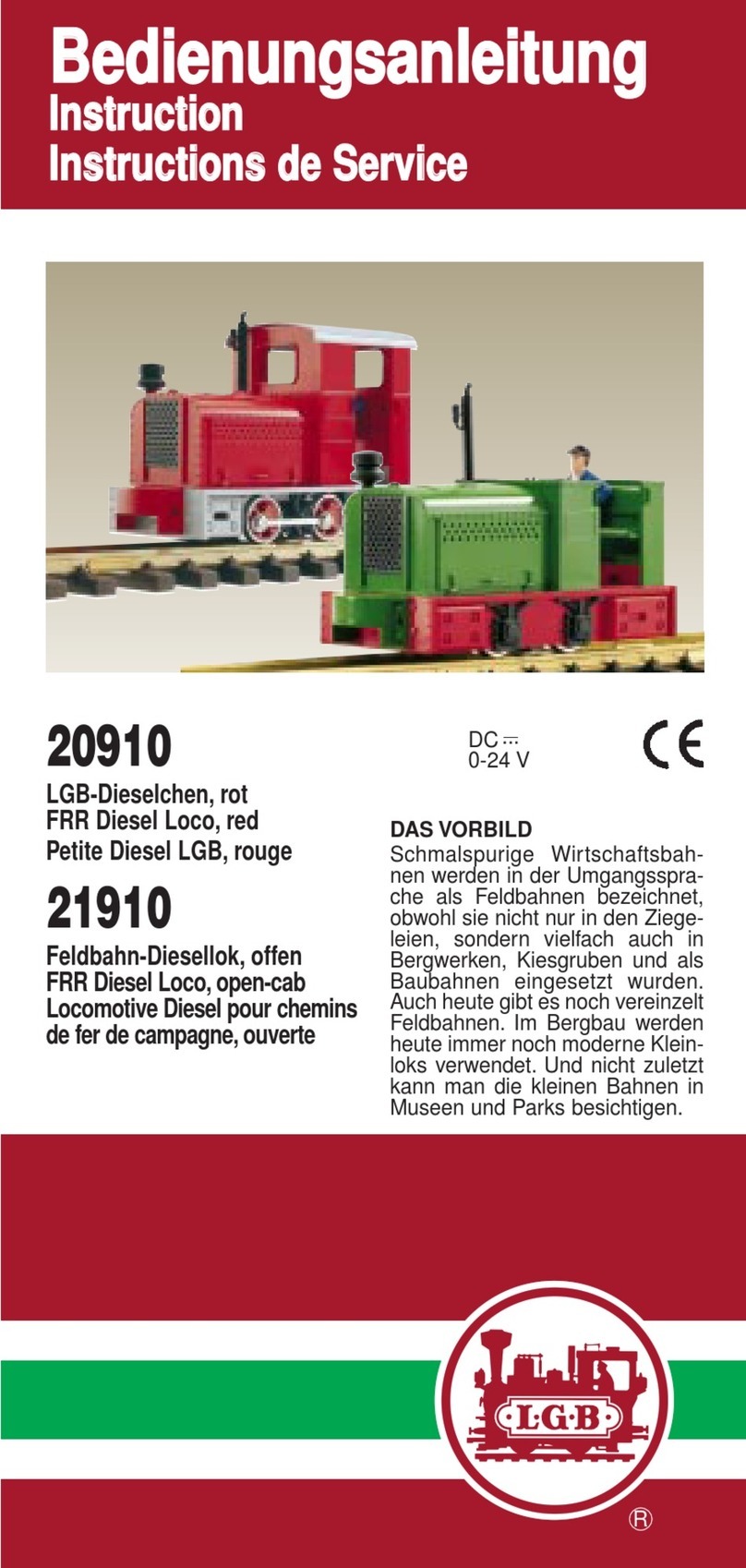
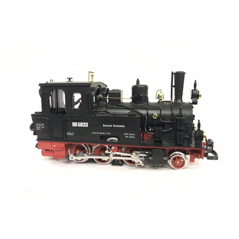
LGB 21811 User manual

CERTIFIKAT
DC
0-24 V
...
Bedienungsanleitung
Instruction
Instructions de Service
8.869110.342 1.9 1004 PF
GARANTIE
Unsere Produkte sind Präzisions-
wertarbeit in Design und Technik. Wie bei
einer wertvollen Uhr werden feinstme-
chanische Präzisionsteile von Hand ge-
fertigt. Permanente Materialkontrollen,
Fertigungskontrollen und die Endkon-
trolle vor Auslieferung garantieren unser
gleichbleibend hohes Qualitätsniveau.
Um wirklich ungetrübten Spaß zu haben,
lesen Sie bitte diese Garantie- und
Bedienungsanleitung.
Wir (ERNST PAUL LEHMANN PATENT-
WERK) gewähren auf dieses Produkt
weltweit eine Garantie von 2 Jahren ab
dem Erstkauf für Fehlerfreiheit von
Material und Funktion, sofern dieses
Produkt mit Kaufbeleg bei einem von uns
autorisierten Fachhändler erworben
wurde.
BeiberechtigtenReklamationeninnerhalb
von 2 Jahren nach Kaufdatum werden wir
gegen Vorlage des entsprechenden
Kaufbelegs nach unserem Ermessen
kostenlos nachbessern, bzw. kostenlosen
Ersatz liefern. Sollten Nachbesserung
oder Ersatzlieferung unmöglich sein, so
räumen wir Ihnen nach unserem Er-
messen eine angemessene Minderung
ein oder erstatten Ihnen statt dessen den
Kaufpreis zurück.
Unabhängig von diesen Garantie-
leistungen bleiben Ihnen selbstverständ-
lich Ihre gesetzlichen Ansprüche insbe-
sondere wegen Sachmängel erhalten.
Um einen Anspruch auf Garantieleistung
geltend zu machen, übergeben Sie bitte
das beanstandete Produkt, zusammen
mit dem Kaufbeleg, Ihrem von uns auto-
risierten Händler. Um einen autorisierten
Händler zu finden, wenden Sie sich bitte
an eine der unten aufgeführten Service-
Abteilungen. Sie können das Produkt
auch, zusammen mit dem Kaufbeleg, an
eine der beiden unten aufgeführten
Serviceabteilungen einschicken. Die
Einsendung erfolgt zu Ihren Lasten.
ERNST PAUL LEHMANN PATENTWERK
Service-Abteilung Garantie
Saganer Str. 1-5
90475 Nürnberg
Deutschland
Telefon (09 11) 83 707-0
LGB OF AMERICA
Warranty Service Department
6444 Nancy Ridge Drive
San Diego, CA 92 121
USA
Tel: (858) 535-93 87
Bitte beachten Sie:
- Für Schäden durch unsachgemäße
Behandlung oder Fremdeingriff sowie für
Verschleißteile besteht kein Garantie-
anspruch.
- Transformatoren und Regler unterliegen
strengen CE-UL-Vorschriften und dürfen
nur vom Hersteller geöffnet und repariert
werden. Zuwiderhandlungen bewirken
zwingend Garantieverlust und generelle
Reparaturverweigerung.
- Nur für USA: Diese Garantie gibt Ihnen
genau definierte Rechte. Weiterhin ver-
bleiben Ihnen unter Umständen je nach
Bundesstaat weitere Rechte.
Wir sind sehr stolz auf unsere Produkte.
Wir alle hoffen, daß sie Ihnen viele Jahre
lang Freude bereiten.
GARANTIE
Nos produits de qualité supérieure sont le
résultat du mariage de l’innovation et de
la technologie. À l’instar d’une montre
précieuse, tous les composants sont
fabriqués à la main par nos artisans méti-
culeux. Unprogrammerigoureuxd’assu-
rance de la qualité, de la sélection des
matériaux à l’assemblage et aux vérifica-
tions avant sortie des ateliers, garantis-
sent un haut niveau de qualité constante.
Afin d’obtenir la plus grande satisfaction
de ce produit, veuillez lire la fiche d’ins-
tructions ainsi que cette garantie.
Nous (Ernst Paul Lehmann Patentwerk)
garantissons ce produit, à l’échelle mon-
diale, contre tout vice de matière et de
fabrication, pendant deux ans à partir de
ladated’achatparl’acheteuroriginal,sile
produit a été acheté chez un détaillant
autorisé.
Si vous demandez un recours en garantie
pour un motif jugé recevable, joignez la
preuve de l’achat chez un détaillant auto-
risé et nous réparerons ou remplacerons
le produit à notre discrétion. S’il s’avère
impossible de réparer ou de remplacer le
produit, nous rembourserons, à notre
discrétion, tout ou partie du prix d’achat.
Vous pouvez disposer d’autres droits
légaux en plus de cette garantie, en parti-
culier en cas de vice de matière.
Pour initier une demande de règlement
au titre de cette garantie, veuillez ramener
le produit, avec la preuve d’achat, à votre
revendeur autorisé. Pour trouver l’adres-
se d’un revendeur autorisé, veuillez entrer
en rapport avec l’un des Centres de servi-
ce après-vente cidessous. Vous pouvez
également renvoyer le produit, avec la
preuve d’achat, directement à l’un des
Centres de service après-vente ci-des-
sous. L’expéditeur est responsable des
frais d’expédition, de l’assurance et des
frais de douane.
ERNST PAUL LEHMANN PATENTWERK
Service-Abteilung Garantie
Saganer Str 1-5
90475 Nürnberg
ALLEMAGNE
Tel : (09 11) 83 707 0
LGB OF AMERICA
Warranty Service Department
6444 Nancy Ridge Drive
San Diego CA 92121
ÉTATS-UNIS
Tel : (858) 535-93 87
Veuillez bien noter que :
- Cette garantie ne couvre pas les dom-
mages résultat d’une utilisation inadé-
quate, ni de modification/réparation non
autorisée. Cette garantie ne couvre pas
l’usure normale.
- Les transformateurs et commandes
sont conformes aux normes rigoureuses
CE et UL et ne peuvent être ouverts et
réparés que par le fabricant. Toute viola-
tion à cet égard entraînera la perte impé-
rative de tous les droits de garantie et un
refus de toutes réparations, quelles qu’el-
les soient.
- États-Unis uniquement : Cette garantie
vous donne des droits légaux spéci-
fiques, et vous pouvez également avoir
d’autres droits qui varient d’un État à l’autre.
Nous sommes très fiers de nos produits
et nous vous souhaitons des années d’a-
musement inoubliables avec votre hobby
qui est également le nôtre.
WARRANTY
This precision product is made using
quality designs and technology. Like a
fine timepiece, it has been crafted by
hand. Constant monitoring of materials
and assembly, together with final testing,
ensure a consistent level of high quality.
To get the most enjoyment from this
product, we encourage you to read the
instructions and this warranty.
We (Ernst Paul Lehmann Patentwerk)
warrant this product worldwide for two
years from the date of original consumer
purchase against defects in materials and
workmanship, if purchased from an
authorized retailer.
If you have a valid warranty claim, includ-
ing proof of purchase from an authorized
retailer, we will repair or replace the prod-
uct at our discretion. If it is impossible to
repair or replace the product, we will
refund all or a reasonable portion of the
purchase price at our discretion.
Of course, you may have other legal
rights independent of this warranty, par-
ticularly in the case of material defects.
To make a claim under this warranty,
please bring the product, with the proof
of purchase, to your authorized retailer.
To find an authorized retailer, please con-
tact one of the service departments listed
below. You may also send the product,
with the proof of purchase, directly to one
of the service departments listed below.
You are responsible for any shipping
costs, insurance and customs fees.
ERNST PAUL LEHMANN PATENTWERK
Service-Abteilung Garantie
Saganer Str. 1-5
90475 Nürnberg
Deutschland
Telephone: (09 11) 83 707 0
LGB OF AMERICA
Warranty Service Department
6444 Nancy Ridge Drive
San Diego, CA 92121
USA
Telephone: (858) 535-93 87
Please note:
- This warranty does not cover damage
caused by improper use or unauthorized
modifications/repairs. This warranty does
not cover normal wear and tear.
- Transformers and controls are subject
to strict CE and UL regulations and may
only be opened and repaired by the man-
ufacturer. Any violations automatically
void this warranty and prevent any repair
by us.
- U.S. only: This warranty gives you spe-
cific legal rights, and you may also have
other rights which vary from State to
State.
We are very proud of our products, and
all of us sincerely hope they give you
many years of enjoyment!
Wolfgang, Rolf, Johannes
Richter
Änderungen der technischen Ausführungen vorbehalten.
We reserve the right to make technical alterations without prior notice.
Modifications de constructions réservées.
DAS VORBILD
Nachdem die bisher bei den
Schmalspurbahnen Bayerns, Badens
und Württembergs eingesetzten
Dampfloks ihre Leistungsgrenze
erreicht hatten, gab die Deutsche
Reichsbahn 1930 eine schwere
1´E1´- Einheitslokomotive der Bau-
reihe 9922 in Auftrag, um die bis-
herigen Maschinen zu ersetzen. Im
Zuge der Vereinheitlichung der DR-
Dampflokbaureihen wurden zahlrei-
che genormte Bauteile verwendet,
darunter ein leicht veränderter Kessel
der Normalspur-BR 81. Von der ge-
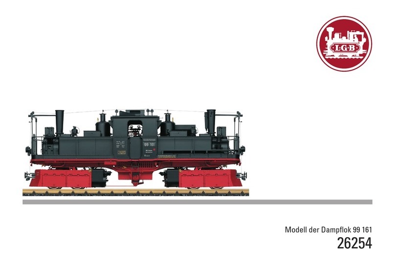
DR-Dampflok 99 7222-5
Art.Nr. 21811
DC
0-24 V
...
DR-Dampflok 99 7222-5, Sound
Art.Nr. 21812
Für drinnen und draussen - For indoors and outdoors
Achtung!
Verpackung und Betriebsanleitung aufbewahren!
Nicht für Kinder unter 8 Jahren geeignet, modellbedingt besteht Quetsch-
und Klemmgefahr durch Antriebsgestänge der Lok.
Nicht für Kinder unter 8 Jahren geeignet, wegen funktions- und modellbe-
dingter scharfer Kanten und Spitzen.
Attention!
This product is not for children under 8 years of age. It has moving parts
that can pinch and bind.
This product is not for children under 8 years of age. This product has
small parts, sharp parts and moving parts.
Attention!
Veuillez conserver l’emballage et le mode d’emploi!
Ne convient pas aux enfants de moins de 8 ans. L’embiellage de la loco-
motive peut pincer les doigts de jeunes enfants.
Ne convient pas aux enfants de moins de 8 ans. Présence de petits élé-
ments susceptibles d’être avalés.
Attenzione!
Conservare l’imballo e le istruzioni per l’uso!
Non adatto a bambini di età inferiore agli 8 anni poiché vi è possibilità a
pericolo di schiacciamento delle dita quando il treno è in funzione.
Non adatto a bambini di età inferiore agli 8 anni in quanto le strutture pre-
sentano spigoli vivi e punte accuminate.
Atención!
Guardar el carton de embalaje y las Instrucciones para el uso!
No adecuado para niños menores de 8 años. Según el modelo, existe el
peligro de sufrir contusiones o de cogerse los dedos a causa del varillaje
de accionamiento de la locomotora. No adecuado para niños menores de
8 años, debido a cantos y puntas peligrosas condicionadas por la función
o el modelo.
Attentie!
Verpakking en gebruiksaanwijzing bewaren!
Niet geschikt voor kinderen onder de 8 jaar omdat deze loc aandrijfstan-
gen bezit waaraan kinderen zich kunnen bezeren.
Niet geschikt voor kinderen onder de 8 jaar omdat dit model funktionele
scherpe kanten en punten bezit.

planten Serie wurden jedoch nur drei
MaschinenvonderBerlinerMaschinen-
bau AG (vorm. L. Schwartzkopf)
gebaut, die auf der Strecke Eisfeld-
Schönbrunn in Thüringen verkehr-
ten. Zwei der Loks kamen wärend
des Krieges nach Norwegen, wo sie
später verschrottet wurden. Die drit-
te Maschine, die 99 222, verblieb in
Thüringen und wurde nach Sti-
llegung ihrer Stammstrecke im Jahr
1966 zur Harzquerbahn umgesetzt.
Hier hat sich die zugstarke Lok
bestens bewährt. Sie diente als
Vorbild für 17 Neubaulokomotiven
der Deutschen Reichsbahn, die seit
den Fünfziger Jahren den grössten
Teil des Verkehrs auf dieser stei-
gungsreichen Bahn bewältigen. Doch
auch die ursprüngliche 99 222 ver-
kehrte zwischenzeitlich als Lok 99
7222-5 im planmäßigen Einsatz auf
den romantischen Strecken im Harz.
Nach einem weiteren Umbau ist die
99 222 auch heute noch täglich im
Harz betriebsfähig zu bewundern.
Auf dreiprozentigen Steigungen der
HSB kann man diese mächtige Lok
bei der harten Arbeit beobachten -
für jeden Dampflokfreund ein unver-
gessliches Erlebnis.
DAS MODELL
Das detaillierte und wetterfeste
Modell ist reichhaltig ausgestattet:
- werkseitig eingebauter MZS-
Decoder onboard für analog und
digital
- Führerstandstüren und
Dachfenster zum Öffnen
- Rauchkammertür und
Tenderabdeckung zum Öffnen
- vierstufiger Betriebsartenschalter
- gekapseltes Getriebe mit zwei
siebenpoligen Bühler-Motoren
- fünf angetriebene Achsen
- zwei Haftreifen
- zwölf Stromabnehmer
- digitales elektronisches
Dampflokgeräusch (nur 21812):
- Dampfausstoß synchron zur
Radumdrehung
- wahlweise lastabhängiges
Dampfgeräusch (mit
Mehrzugsystem)
- Glocke und Pfeife
- Bremsgeräusch
- Luftpumpe, Überdruckventil und
Zischen des Dampfes
- Geräusch des Kohleschaufelns
- Lautstärke-Regler
- Fernbedienung der Sound-
Funktionen (mit Mehrzugsystem)
- Spannungsbegrenzungs-System
- flackerndes Licht aus der
Feuerbüchse
- Triebwerksbeleuchtung
- automatisch in Fahrtrichtung
wechselnde Beleuchtung
- Mehrzweck-Steckdose mit Sicherung
- Länge: ca. 550 mm
- Gewicht: ca. 5000 g
DAS LGB-PROGRAMM
Dieses LGB-Modell gehört zum kom-
pletten LGB-Programm mit mehr als
600 hochwertigen Modellbahnen,
Gleisen und Zubehör der Baugröße
G. Informationen über das LGB-
Programm finden Sie im großen
LGB-Katalog und im Internet bei
www.lgb.de
BEDIENUNG
Das Modell ist eine originalgetreue
Nachbildung der großen Vorbildlok.
Obwohl die Lok über einen sehr lan-
gen Radstand verfügt, durchfährt sie
den kleinsten LGB-Radius “R1”
(11000). Um die Lok problemlos ein-
zusetzen, beachten Sie bitte folgende
Hinweise:
- Verwenden Sie nach Möglichkeit
die größeren Radien “R3” und "R5",
0123
Abb. 1. Lichtraumprofil
Abb. 2. Halter für EPL-Schaltmagnet
17010
Abb. 3, 4. Betriebsartenschalter
Abb. 5. Mehrzweck-Steckdose
Abb. 6. Lautstärkeregler (21812)
Abb. 7. Sicherheitsabdeckung für
Dampfentwickler
Abb. 8. Austauschen des
Dampfentwicklers
Fig. 1. Clearances
Fig. 2. Bracket for 17010 EPL Loco
Magnet
Fig. 3, 4. Operating modes
Fig. 5. Multi-Purpose Socket
Fig. 6. Volume Control (21812)
Fig. 7. Safety cover for smoke gene-
rator
Fig. 8. Replacing the smoke generator
Illustr. 1. Dégagements
Illustr. 2. Support d’aimant pour loco-
motive EPL 17010
Illustr. 3, 4.Modes opératoires
Illustr. 5. Douille à usages multiples
Illustr. 6. Commande de réglage du
volume sonore (21812)
Illustr. 7. Couvercle de sécurité pour le
générateur de fumée
Illustr. 8. Remplacement du générateur
de fumée
D
GB
USA
F
4 53
3
2
1
6
5
012 3
012 3
012 3
012 3
4
7
8
3 4

geplanten Serie wurden jedoch
nur drei Maschinen von der
Berlinernach Eisfelder Talmühle.
Bitte einsteigen und Vorsicht bei
der Abfahrt des Zuges."
5: Kesselfeuer aus/ein (beim
Einschalten ertönt Kohleschaufeln)
6: Überdruckventil
7: Dampfentwickler aus/ein
8: Geräuschelektronik aus/ein
(Tasten 1-4, 6 und 8 sind nur bei
21812 belegt.)
Drücken Sie die entsprechende
Funktionstaste am Lok-Handy oder
am Universal-Handy. Um beispiels-
weise das Bremsgeräusch auszulö-
sen, beim Handy die Taste “2”
drücken.
Bei Verwendung der mit “p” gekenn-
zeichneten MZS-Bausteine können
die Funktionen dieser Lok auch “par-
allel” ausgelöst werden, d. h., es ent-
fällt die Pause, die beim “seriellen”
Auslösen entsteht, während der
Befehl “abgearbeitet” wird.
Parallel: Befehl wird direkt gesendet
und verarbeitet.
Seriell: Befehl wird als Aneinander-
reihung von “1”-Befehlen gesendet,
z. B. 3 = 1 + 1 + 1).
Diemeisten MZS-Komponenten lassen
sich über ein Upgrade auf parallele
Funktionsauslösung umstellen (Aus-
nahmen:MZS-Zentraleder1.Generation
55000 und Lokmaus 55010). Weitere
Informationen erhalten Sie bei Ihrem
Fachhändler oder bei www.lgb.de.
Beim Betrieb mit dem Mehrzug-
system verfügt die Lok über eine
Lastnachregelung: Die Motordreh-
zahl (und damit unter normalen
Bedingungen die Geschwindigkeit)
wird konstant gehalten, auch wenn
sich die Belastung der Lok ändert, z.
B. in Kurven oder auf Steigungen.
Die Lastnachregelung funktioniert
nicht bei Höchstgeschwindigkeit, da
dann keine Spannungsreserve zur
Verfügung steht.
Falls gewünscht, können zahlreiche
Funktionen des Decoder onboard mit
einem PC über das MZS-PC-
Decoderprogrammiermodul 55045
individuell programmiert werden, so
z. B. Beschleunigung, Bremsver-
zögerung, Fahrtrichtung und vieles
andere (siehe Anleitung für Fortge-
schrittene). Diese Funktionen kön-
nen auch über das Universal-Handy
55015 programmiert werden.
Beleuchtung
Die Beleuchtung des Modells wech-
selt mit der Fahrtrichtung. Die
Triebwerke sind ebenfalls vorbildget-
reu beleuchtet. Falls Ihnen die
Triebwerksbeleuchtung zu hell ers-
cheint, können Sie die Glühlampen
gegen 24-Volt-Glühlampen (68513)
austauschen.
Das Modell hat eine Mehrzweck-
Steckdose für Flachstecker an der
Rückwand (Abb. 5). Über die
Steckdose können Sie LGB-Wagen
mit Beleuchtung oder mit Geräusch-
elektronik an die Gleisspannung ans-
chließen. Dazu die Abdeckung von
der Steckdose abziehen. Sollte die
Abdeckung zu fest sitzen, diese vor-
sichtig mit einem kleinen Schrauben-
zieher heraushebeln. (Jedoch nicht
das äußere rechteckige Gehäuse
herausziehen.)
Dampfentwickler
Das Modell ist mit einem Dampf-
entwickler ausgestattet. Ein
Fläschchen mit LGB-Dampf- und
Reinigungsflüssigkeit liegt bei. Den
Schornstein nur zur Hälfte mit der
Flüssigkeit füllen. Wenn zu viel
Flüssigkeit verwendet wird, kann
diese nicht verdampfen.
Achtung! Das Heizelement in der
Mitte des Dampfentwicklers nicht
6
um die Betriebssicherheit zu er-
höhen und einen vorbildgetreuen
Einsatz zu ermöglichen.
- Beim Durchfahren von Kurven ragt
das Führerhaus weit nach außen
(Abb. 1). Überprüfen Sie deshalb
das Lichtraumprofil Ihrer Anlage,
bevor Sie das Modell fahren lassen.
Vor Brücken, Bahnsteigen oder
Tunnels sollte unbedingt ein gera-
des Gleis eingebaut werden, damit
die Lok sich gerade ausrichten
kann, bevor sie die Hindernisse
passiert.
Vorbereitung
Falls Sie die Lok mit einem EPL-
Schaltmagneten 17010 ausrüsten
wollen, so ist es notwendig, die bei-
liegende Montageplatte unter dem
Getriebe zu befestigen. (Der EPL-
Schaltmagnet dient zum Auslösen
des EPL-Gleiskontakts 17100. Er ist
separat erhältlich.) Die Montage-
platte kann wahlweise auf dem vor-
deren oder dem hinteren Teil des
Getriebes montiert werden:
- Neben dem Knickgelenk auf der
Unterseite des Getriebes befinden
sich auf beiden Seiten jeweils zwei
Schrauben (Abb. 2).
- Die vorderen oder die hinteren
Schrauben lösen.
- Die Montageplatte so auflegen,
dass die eingeprägte Nummer nach
unten weist und nicht sichtbar ist.
Dabei muss die Halterung zum
Getriebeende weisen und nicht zum
Knickgelenk.
- Die Montageplatte mit den beiden
Getriebeschraubenauf dem Getriebe
befestigen.
- Der EPL-Schaltmagnet 17010 lässt
sich jetzt zwischen den eingepräg-
ten Nuten auf der Getriebeunter-
seite und auf der Montageplatte mit
doppelseitigem Klebeband befesti-
gen.
Betriebsarten
Das Modell hat einen vierstufigen
Betriebsarten-Schalter im Führerstand
(Abb. 3, 4):
Position 0: Stromlos abgestellt
Position 1: Beleuchtung und Dampf-
entwickler eingeschaltet
Position 2: Lokmotoren, Dampfent-
wickler und Beleuchtung
eingeschaltet
Position 3: Sound (nur 21812),
Lokmotoren, Dampfent-
wickler, Beleuchtung und
Kesselfeuer eingeschaltet
(werkseitige Einstellung
bei Auslieferung)
Achtung! Nicht mehrere Triebfahr-
zeuge mit unterschiedlichem Anfahr-
verhalten zusammenkuppeln, da dies
zu Getriebeschäden führen kann.
Mehrzugsystem
Das Modell ist bereits werkseitig mit
Decoder onboard für das LGB-
Mehrzugsystem ausgerüstet. Es
kann unverändert auf herkömmli-
chen analogen Anlagen oder mit dem
digitalen Mehrzugsystem eingesetzt
werden. Zum Einsatz mit dem LGB-
Mehrzugsystem ist das Modell auf
Lokadresse 03 programmiert.
Informationen zum Programmieren
der Lokadresse finden Sie in den
Anleitungen der einzelnen MZS-
Regler.
Beim Betrieb mit dem Mehrzug-
system können Funktionen der Lok
ferngesteuert werden. Über die
Beleuchtungstaste (“9” bei Handys)
wird die Lokbeleuchtung ein- und
ausgeschaltet. Über die Funktions-
tasten werden folgende Funktionen
betätigt:
1: Pfeife
2: Bremsgeräusch
3: Glocke
4: Ansage: "Sehr geehrte Fahrgäste,
in Gleis 1 steht der Personenzug
7

und über das Mehrzugsystem finden
Sie im LGB-Katalog.
Achtung! Nach längerer Benutzung
kann Abrieb durch mechanische Teile
entstehen, der sich in Teppichen und
anderen Materialien festsetzt.
Bedenken Sie dies beim Aufbau der
Gleise. Bei Schäden übernimmt Ernst
Paul Lehmann Patentwerk keine
Haftung.
WARTUNG
Schwierigkeitsgrade der
Wartungsarbeiten
- Einfach
- Mittel
- Fortgeschritten
Achtung! Bei unsachgemäßer Wartung
wird Ihre Garantie ungültig. Um fach-
gerechte Reparaturleistungen zu
erhalten, wenden Sie sich an Ihren
Fachhändler oder an die LGB-
Service-Abteilung (siehe Autorisierter
Service).
Hinweis: Für Experten gibt es weitere
Wartungsanleitungen für viele LGB-
Artikel im Internet unter www.lgb.de
Schmierung
Die Achslager und die Lager des
Gestänges hin und wieder mit je
einem Tropfen LGB-Pflegeöl (50019)
ölen.
Reinigung
Sie können das Gehäuse Ihres
Modells mit einem milden Reini-
gungsmittel reinigen. Das Modell
nicht in das Reinigungsmittel eintau-
chen.
Achtung! Das Modell 21812 ist mit
Sound ausgestattet. Der Laut-
sprecher darf nicht direkt mit Wasser
in Berührung kommen.
Austauschen der Glühlampen
Lampen (vorne): Lampengehäuse
vom Modell abziehen. Eingesteckte
Glühlampe aus dem Sockel ziehen.
Neue Glühlampe einstecken. Modell
wieder zusammenbauen.
Lampe (hinten): Vorsichtig das Glas
von der Laterne hebeln. Mit einer
Pinzette die eingesteckte Glühlampe
aus der Fassung ziehen. Neue
Glühlampe einsetzen. Modell wieder
zusammenbauen.
Innenbeleuchtung und Triebwerks-
beleuchtung: Glühlampe mit einer
Pinzette aus der Fassung ziehen.
Neue Glühlampe einstecken.
Austauschen des
Dampfentwicklers
- Abdeckung aus dem Schornstein
ziehen (Abb. 7).
- Beschädigten Dampfentwickler
(Schornsteineinsatz) mit einer
Spitzzange oder einer Pinzette aus
dem Schornstein ziehen.
- Kabel durchtrennen.
- Kabel mit dem neuen
Dampfentwickler verbinden. Dabei
die abisolierten Kabelenden verdre-
hen und isolieren (Abb. 8).
- Neuen Dampfentwickler in den
Schornstein schieben.
- Modell wieder zusammenbauen.
Austauschen des Haftreifens
- Schrauben des Gestänges lösen
und Gestänge von den Radzapfen
abnehmen.
- Mit einen kleinen flachen
Schraubendreher den alten
Haftreifen entfernen:
- Den alten Haftreifen aus der Rille
(Nut) im Treibrad hebeln.
- Vorsichtig den neuen Haftreifen
über das Rad schieben und in die
Rille (Nut) des Rads einsetzen.
- Überprüfen, dass der Haftreifen
richtig sitzt.
- Modell wieder zusammenbauen
98
berühren. Es ist heiß und zerbre-
chlich. Nicht für Kinder. Benutzung
nur durch Erwachsene!
Achtung! Nur LGB-Dampf- und
Reinigungsflüssigkeit (50010) ver-
wenden. Andere Flüssigkeiten kön-
nen Ihre Lok beschädigen. Hinweise
auf der Probepackung bzw. der
Flasche 50010 beachten.
Hinweis: Der Dampfentwickler kann
“trocken” ohne Dampfflüssigkeit
betrieben werden.
Elektronischer Sound bei 21812
Die digitale Geräuschelektronik die-
ser Lokomotive gibt den echten
Sound einer Vorbildlok wieder. Das
Modell hat einen Lautstärke-Regler
hinter der Rauchkammertür (Abb. 6).
Das Dampfgeräusch ist mit der Rad-
umdrehung synchronisiert. Der Takt
des Abdampfgeräusches ist werksei-
tig auf 2 Auspuffschläge pro Radum-
drehung eingestellt. Dies kann vor-
bildgetreu auf 4 Auspuffschläge pro
Radumdrehung geändert werden,
indem Bit 7 in CV54 auf "64" pro-
grammiert wird (siehe Anleitung für
Fortgeschrittene).
Zusätzlich zum Abdampfgeräusch ist
das Zylindernebengeräusch zu hören.
Beim Betrieb mit dem LGB-Mehrzug-
system kann der Sound lastabhängig
ausgegeben werden, so dass wie
beim Vorbild bei Bergabfahrt oder
beim Bremsen nur die Zylinder-
nebengeräusche zu hören sind. Dazu
wird Bit 4 in CV54 auf "8" program-
miert (siehe Anleitung für Fortge-
schrittene).
Alle nachfolgend beschriebenen
Sound-Funktionen lassen sich auch
direkt über das Mehrzugsystem aus-
lösen (siehe Mehrzugsystem).
Glocke und Pfeife: Wenn die Lok
anfährt, ertönt die Pfeife. Glocke und
Pfeife können auch mit dem beilie-
genden LGB-Sound-Schaltmagneten
(17050) ausgelöst werden. Der
Schaltmagnet lässt sich zwischen die
Schwellen der meisten LGB-Gleise
klipsen.
Der Magnet befindet sich seitlich ver-
setzt unter dem eingeprägten LGB-
Logo. Platzieren Sie den Magneten
auf einer Seite, um die Pfeife auszu-
lösen, wenn die Lok diese Stelle
überquert. Bei Anordnung auf der
anderen Seite ertönt die Glocke.
Bremse: Wenn die Lok langsam
abgebremst wird, ertönt das
Geräusch der “kreischenden”
Bremsen. Für das Auslösen des
Geräusches benötigt man etwas
Fingerspitzengefühl.
Standgeräusch: Beim Betrieb mit
dem Mehrzugsystem hört man im
Stand das Rauschen des Dampfes im
Kessel, sowie abwechselnd Luft- und
Wasserpumpe.
Um beim Analogbetrieb die Stand-
geräusche zu hören, muss eine
geringe Spannung (ca. 6,5 Volt) an
den Gleisen anliegen. Drehen Sie
dazu den Regler auf eine Fahrstufe,
in der die Lok noch nicht anfährt, die
Geräusche jedoch bereits zu hören
sind.
Hinweis: Um beim Analogbetrieb bei
ausgeschaltetem Trafo und bei Fahrt-
richtungswechseln Standgeräusche
zu erhalten, muss die Stand-
geräusch-Stromversorgung 65011
eingebaut werden. Bei Fragen zum
Einbau der 65011 wenden Sie sich
bitte an Ihren Fachhändler.
Stromversorgung
Achtung! Um Sicherheit und
Zuverlässigkeit zu gewährleisten,
darf das Modell nur mit LGB-Trafos
und Fahrreglern betrieben werden.
Bei Verwendung von anderen Trafos
wird Ihre Garantie ungültig.
Für dieses Modell einen LGB-Trafo
mit mehr als 1 A Fahrstrom einset-
zen. Weitere Informationen über die
LGB-Trafos und Fahrregler zur
Verwendung im Haus oder im Freien

Hinweis: Das Modell hat zwei Haft-
reifen.
Ersatzteile
50010 Dampf- und Reinigungsöl
50019 Pflegeöl
51020 Getriebefett
63120 Stromabnehmerkohlen mit
Hülsen, 8 Stück
(2 Packungen nötig)
63218 Schleifkontakte, 2 Stück
(2 Packungen nötig)
65853 Schornsteineinsatz, 5 V
68511 Steckglühlampe klar, 5 V,
10 Stück
69184 Haftreifen 46,5 mm,
10 Stück
ANLEITUNG FÜR
FORTGESCHRITTENE
MZS-Decoder onboard
Programmieren der Funktionswerte
Zahlreiche Funktionen des Decoder
onboard können individuell program-
miert werden. Dazu werden
Funktionswerte in Registern (Con-
figuration Variables - CVs) mit einem
PC über das MZS-PC-Decoder-
programmiermodul 55045 program-
miert. Sie können die Funktionswerte
auch mit dem Universal-Handy
55015 programmieren.
Hinweise:
- Zum normalen Betrieb ist es nicht
notwendig, die Funktionswerte zu
ändern.
- Um bei Fehlprogrammierungen den
Auslieferungszustand der wichtig-
sten Register des MZS-Decoders
wieder zu programmieren, Funk-
tionswert 55 in Register CV 55 ein-
geben. Dabei wird auch die
Lokadresse wieder auf den werk-
seitigen Wert programmiert. Beim
Programmieren mit 55015 den
Programmiermodus “P” wählen (in
der Anzeige erscheint “P --”). Dann
aufeinander folgend 6, 5 und 5 ein-
geben und rechte Pfeiltaste drüc-
ken. Die Anzeige zeigt erneut “P --”:
5, 5 und 5 eingeben und nochmals
rechte Pfeiltaste drücken.
1110
Programmiert werden folgende CVs:
Register Belegung Bereich Werkseitige
Einstellung
CV1 Lokadresse (00-22) [3]
CV2 Anfahrspannung (0-255) [5]
Spannungswert bei Fahrstufe 1 - falls Lok erst in höherer
Fahrstufe anfährt, Wert erhöhen.
CV3 Beschleunigung (1 = schnelle Beschleunigung, (1-255) [3]
255 = langsame B.)
CV4 Verzögerung (1 = schnelles Bremsen, (1-255) [3]
255 = langsames Bremsen)
CV5 Maximale Fahrpannung (1-255) [255]
Spannungswert für höchste Fahrstufe - wenn geringere
Höchstgeschwindigkeit gewünscht wird, Wert verringern.
CV5 nach Eingabe von CV6 (beim Programmieren mit älteren
55015) Funktionswert im zu programmierenden Register
CV6 CV-Nr. des zu programmierendes Register (beim
Programmieren mit älteren 55015)
CV29 NMRA-Konfiguration [4]
Bit-Programmierung
Bit 1: Fahrtrichtung, 0 = normal, 1 = invers [0]
Bit 2: Fahrstufen, 0 = 14 (LGB), 2 = 28 [0]
Bit 3: Analogbetrieb, 0 = gesperrt, 4 = möglich [4]
Bit 4: nicht besetzt [0]
Bit 5: Fahrstufentabelle, 0 = werkseitig programmiert,
16 = vom Anwender programmiert [0]
Bit 6: Adressbereich, 0 = 0-127 (LGB), 32 = 128-10039 [0]
Zum Programmieren die Werte für die einzelnen Bits
addieren und das Ergebnis als Funktionswert programmieren.
Hinweis: Um eine Lok auf inverse Fahrtrichtung zu
programmieren (z. B. F7 A-B-A-Kombination),
Funktionswert 5 programmieren
Achtung! Lokadressen 128-10039 und 28 Fahrstufen sind
nicht mit dem LGB-MZS verwendbar
CV49 Spannungswert für Funktionsausgang F1 (1-32) [32]
(Lokspezifisch, nicht verändern, da sonst Funktionen
beeinträchtigt oder zerstört werden können)
CV50 Spannungswert für Lichtausgänge (siehe CV49) (1-32) [5]
CV51 Schalttaste für Funktionsausgang F1 [13]
0 = Lichttaste 9
1 = Taste 1 (Tasten 2-8 nicht belegt)
9 = Taste 1 (Tasten 2-8 ebenfalls belegt)
10 = Taste 2
11 = Taste 3
12 = Taste 4
13 = Taste 5
14 = Taste 6
15 = Taste 7
16 = Taste 8

1312
CV62 Lastnachregelung: Nachregelstärke (0-255) [255]
Begrenzt die Nachregelung auf eine maximale Abweichung
vom Sollwert. Bei besonders großen Belastungen des
Motors wird nur bis zu diesem Differenzwert nachgeregelt -
für realistischeren Betrieb, damit Loks z. B. bei Bergfahrt
nicht voll nachregeln.
0 = keine Nachregelung, 255 = maximale Nachregelung
CV 67 Fahrstufentabelle vom Anwender programmiert (siehe CV 29) (0-255)
bis Die Geschwindigkeitstabelle wird immer mit 28 Werten
CV 94 abgelegt, die in CV 67 bis CV 94 programmiert werden.
Beim Betrieb mit dem LGB-MZS wird jeder zweite Wert
übersprungen (14 Fahrstufen).
Werkseitig programmierte Fahrstufentabelle:
7, 9, 11, 13, 16, 20, 24, 28, 32, 36, 42, 48, 54, 60, 68, 76,
84, 92, 102, 112, 124, 136, 152, 168, 188, 208, 230, 255
Vorgeladene Werte der programmierbaren Kurve:
8, 16, 24, 32, 40, 48, 56, 64, 72, 80, 88, 96, 104, 112, 120,
128, 136, 144, 152, 160, 168, 176, 184, 192, 208, 224,
240, 255
Hinweis: Fahrstufentabelle ist werkseitig programmiert
und braucht nicht verändert werden. Zum Programmieren
MZS-PC-Decoderprogrammiermodul 55045 empfehlenswert.
Beispiel zur Bit-Programmierung:
CV 29: Die Lok soll mit inverser Fahrtrichtung mit vom
Anwender programmierter Fahrstufentabelle fahren,
Analogbetrieb soll möglich sein:
Bit 1 = 1, Bit 2 = 0, Bit 3 = 4, Bit 4 = 0, Bit 5 = 16,
Bit 6 = 0. 1+4+16=21.
Also CV 29 auf Funktionswert 21 programmieren.
64 = Lichttaste 9 (ein nur bei Rückwärtsfahrt)
65 = Taste 1 (ein nur bei Rückwärtsfahrt)
128 = Lichttaste 9 (ein nur bei Vorwärtsfahrt)
129 = Taste 1 (ein nur bei Vorwärtsfahrt)
(Lokspezifisch, nicht verändern, da sonst Funktionen
beeinträchtigt oder zerstört werden können)
CV52 Schalttaste Licht vorne (siehe CV51) [128]
CV53 Schalttaste Licht hinten (siehe CV51) [64]
CV54 LGB-Konfiguration [2]
Bit-Programmierung
Bit 1: Übernahme-Funktion, 0 = aus, 1 = ein [0]
Bit 2: Lastnachregelung mit MZS, 0 = aus, 2 = ein [2]
Bit 3: Lastnachregelung ananlog, 0 = aus, 4 = ein [0]
Bit 4: Lastabhängiges Dampfgeräusch, 0 = aus, 8 = ein [0]
Bit 5: 0 = F1 konstant, 16 = F1 blinkend [0]
Bit 6: 0 = F2 konstant, 32 = F2 blinkend [0]
Bit 7: 0 = Zwei Auspuffschläge/Radumdrehung,
64 = Vier Auspuffschläge [0]
Bit 8: Automatisches Bremsgeräusch, 0 = ein, 128 = aus [0]
Zum Programmieren die Werte für die einzelnen Bits
addieren und das Ergebnis als Funktionswert programmieren.
Die Werte für Bit 5-8 variieren von Lok zu Lok. Die Werte
für Ihre Lok können über das MZS-PC-Decoder-
programmiermodul 55045 ausgelesen werden.
Übernahme-Funktion ein: Beim Betrieb mit 55015 kann
nach Anwählen der Lok die Reglerstellung 2 Sekunden lang
nachgeregelt werden, ohne dass die Lok anhält
CV55 Wiederherstellen des Auslieferungszustands
Programmierung:
6-55->
5-55->
CV56 Spannungswert für Funktionsausgang F2 (1-32) [5]
(Lokspezifisch, nicht verändern, da sonst Funktionen
beeinträchtigt oder zerstört werden können)
CV57 Schalttaste für Funktionsausgang F2 (siehe CV51) [15]
CV58 Pausen-Pendelzeit (Analogbetrieb) (0,5 Sekunden x Wert) (0-255) [0]
Wenn die analoge Fahrspannung umgepolt wird, wartet
die Lok entsprechend der eingestellten Zeit, bevor sie in
der neuen Fahrtrichtung anfährt
CV60 Lastnachregelung: Maximaler Nachregelfaktor (1-255) [10]
Legt maximale Erhöhung oder Verringerung des
Spannungswerts fest, der pro Zeiteinheit (aus CV61)
nachgeregelt wird.
1 = kleine Nachregelungsschritte,
255 = große Nachregelungsschritte Werkseitige
Programmierung ist optimal an LGB-Motoren angepasst.
CV61 Lastnachregelung: Nachregelgeschwindigkeit (0-255) [5]
Legt fest, wie oft pro Sekunde nachgeregelt wird - ob die
Lok auf Kurven und Steigungen sofort oder träge reagiert
0 = schnelle Nachregelung, 255 = sehr langsame Nachregelung

15
21811
DR Steam Loco, 99 7222-5
21812
DR Steam Loco, 99 7222-5,
Sound
THE PROTOTYPE
In the late 1920s, the Deutsche
Reichsbahn found that the existing
steam locomotives on the narrow
gauge lines of Bavaria, Baden and
Wurttemberg no longer were power-
ful enough. To replace them, the DR
designed the heavy 2-10-2 steam
locomotive class 9922. As part of a
drive toward standardizing DR steam
locos, numerous parts were shared
with other locomotive classes. For
example, the new loco used the
slightly modified boiler of the stan-
dard gauge class 81. Of the planned
series, only three locomotives were
built by Berliner Maschinenbau AG
(successors of L. Schwarzkopf).
They operated on the Eisfeld-
Schönbrunn line in Thuringia. Two of
these locos were transferred to
Norway during World War II, where
they later were scrapped. The third
locomotive, the 99 222, remained in
Thuringia until that line was closed in
1966. Then the loco was transferred
to the Harzquerbahn.
Here, the powerful locomotive has
been very successful. In the 1950s, it
served as prototype for 17 new nar-
row gauge steam locomotives that
since then have hauled the bulk of
the traffic in the Harz Mountains. And
the original 99 222 continues to pull
regular trains. For a while, it was
numbered 99 7222-5 until its old
number was returned after yet anoth-
er rebuild. For steam enthusiasts,
experiencing this massive locomo-
tive on the three-percent grades of
the picturesque Harzquerbahn line is
a unique and unforgettable experi-
ence.
THE MODEL
This detailed replica features:
- weather-resistant construction
- factory-installed onboard decoder
for MTS and analog operation
- opening cab doors and roof hatch
- opening smokebox door and ten-
der cover
- four-way power control switch
- protected gearbox with two seven-
pole Bühler motors
- ten powered wheels
- two traction tires
- twelve power pickups
- digital electronic sound (only
21812):
- synchronized steam chuffs
- optional load-dependent steam
chuffs (with Multi-Train System)
- bell and whistle sounds
- brake sounds
- air pump, safety valve and steam
sounds
- coal shoveling sound
- volume control
- remote control of sound features
(with Multi-Train System)
- voltage stabilization circuit
- smoke generator
- simulated firebox fire
- drivetrain illumination
- automatic directional lanterns
- one multi-purpose socket with cir-
cuit breaker
- length: ca. 550 mm (21.7 in)
- weight: ca. 5000 g (11 lb)
THE PROGRAM
This LGB model is part of the com-
plete LGB program of more than 600
14
Beim Programmieren mit neueren
Universal-Handys 55015P (“parallel”
mit Programmiermodus “C”) und
MZS-PC-Decoderprogrammiermodulen
55045 werden alle Werte direkt pro-
grammiert.
Programmieren mit älteren
Universal-Handys 55015 (mit
Programmiermodus "P"):
- Register CV 1 bis CV 4 können
direkt programmiert werden, indem
der gewünschte Funktionswert in
das betreffende Register eingetra-
gen wird.
- Für höhere CVs gilt:
- In Register CV 6 die Nummer des
zu programmierenden Registers
eintragen.
- In Register CV 5 wird dann der
gewünschte Funktionswert pro-
grammiert.
Programmierbeispiel:
Übernahme-Funktion einschalten
(Register CV 54 auf Funktionswert 3
programmieren).
Programmierablauf:
- Anzeige zeigt “P --”
- Register CV 6 wählen
(Taste 6 drücken).
- 54 eingeben (zu programmieren-
des Register).
- Programmierablauf auslösen
(rechte Pfeiltaste drücken).
- Anzeige zeigt “P --”
- Register CV 5 wählen
(Taste 5 drücken).
- 3 eingeben (zu programmierender
Funktionswert).
- Programmierablauf auslösen
(rechte Pfeiltaste drücken).
AUTORISIERTER SERVICE
Bei unsachgemäßer Wartung wird
Ihre Garantie ungültig. Um fachge-
rechte Reparaturleistungen zu erhal-
ten, wenden Sie sich an Ihren
Fachhändler oder an die LGB-
Service-Abteilung:
Ernst Paul Lehmann Patentwerk
Reparatur-Abteilung
Saganer Straße 1-5
D-90475 Nürnberg
DEUTSCHLAND
Tel.: (0911) 83707 0
Telefax: (0911) 83707 70
Die Einsendung erfolgt zu Ihren
Lasten.
Hinweis: Informationen zur LGB und
zu LGB-Vertretungen in aller Welt fin-
den Sie im Internet unter www.lgb.de
VORSICHT! Dieses Modell ist nicht
für Kinder unter 8 Jahren geeignet.
Das Modell hat kleine, scharfe und
bewegliche Teile. Am Lokgestänge
besteht Quetsch- und Klemmgefahr!
Verpackung und Bedienungsanleitung
aufbewahren.
Artikel, technische Daten und
Lieferdaten können sich ohne
Vorankündigung ändern. Einige
Artikel sind nicht überall und über
alle Fachhändler erhältlich. Einige
Abbildungen zeigen Handmuster.
LGB, LGB of America, LEHMANN
und der LGB TOYTRAIN-Schriftzug
sind eingetragene Marken der Firma
Ernst Paul Lehmann Patentwerk,
Nürnberg, Deutschland. Andere
Marken sind ebenfalls geschützt. ©
2004 Ernst Paul Lehmann Patentwerk.
GB
USA

1716
geehrte Fahrgäste, in Gleis 1 steht
der Personenzug nach Eisfelder
Talmühle. Bitte einsteigen und
Vorsicht bei der Abfahrt des
Zuges." (Dear passengers, on
track 1 waits the passenger train
to Eisfelder Talmühle. All aboard
and be careful as the train
leaves.)
5: Flickering firebox off/on (when
turning on, coal shoveling sound
is heard)
6: Safety valve
7: Smoke generator off/on
8: Sound off/on
(Function buttons 1-4, 6 and 8 only
for 21812.)
With a Loco Remote or Universal
Remote, press the numbered loco
function buttons. For example, to
trigger the brake sound, press button
“2” on the Loco Remote or Universal
Remote.
When using the MTS components
marked with a “p,” this loco can
receive "parallel" function com-
mands, which eliminate the pause
that occurs when a "serial" command
is received.
Parallel: Command is send directly.
Serial: Command is send as a string
of "1" commands, for example, 3 = 1
+ 1 + 1).
Most MTS components can be
upgraded to parallel function com-
mands (Exceptions: first generation
55000 MTS Central Station, 55010
Train Mouse). For more information,
contact your authorized retailer or go
to www.lgb.com.
When operating with the Multi-Train
System, the loco features a “Back-
EMF” function. This keeps the motor
speed constant (and under normal
conditions the loco speed), even
when the load of the loco changes,
for example, in curves or on grades.
This feature does not work at top
speed, because additional voltage
must be available to overcome any
added load.
If desired, numerous functions of the
onboard decoder, such as accelera-
tion, braking, direction of travel and
many others, can be programmed
using a PC and the 55045 MTS PC
Decoder Programming Module (see
Instructions for advanced users).
These functions also can be pro-
grammed with the 55015 Universal
Remote.
Lighting
This model features directional light-
ing. As on the prototype, the drive-
trains are illuminated. If you prefer a
less bright illumination of the drive-
trains, replace the light bulbs with 24
volt bulbs (68513).
The model has a "flat" multi-purpose
socket, with a removable cover, on
the rear wall (Fig. 5). This socket can
be used to provide track power to
LGB cars with lighting or sound elec-
tronics.
To remove the cover of the socket,
pull it straight out. If the cover is
tight, gently use a small straight
screwdriver to pry it out. (Do not pull
out the rectangular outer housing.)
Smoke Generator
This model is equipped with a smoke
generator. A small supply of LGB
Smoke and Cleaning Fluid is included
with this model. For best operation,
fill the generator halfway with fluid. If
the generator is overfilled, it will not
convert the fluid into smoke.
Attention! Never touch the heating
element in the center of the smoke
generator. It is hot and fragile. Not
for children. Only for use by adults!
Attention! Only use LGB Smoke and
Cleaning Fluid (50010). Other fluids
quality G-scale trains, track sections
and accessories. To learn more about
the many other products in the LGB
program, see the big LGB catalog or
visit www.lgb.com
OPERATION
This model is an accurate replica of
the massive original locomotive, but
despite its size, the model will nego-
tiate "R1" curves (11000). However,
this combination of features requires
some special considerations:
- For more realistic and reliable oper-
ation, use the larger "R3" and "R5"
curves whenever possible.
- In curves, the cab swings out (Fig.
1). Make sure that your layout has
the necessary clearances before
you operate the model. Place a
straight track section in front of
bridges, tunnels or station plat-
forms, to allow the loco to realign
before passing these obstacles.
Preparation
If you want to equip the model with
the 17010 EPL Loco Magnet, you
have to install the included mounting
bracket underneath the gearbox.
(The EPL Loco Magnet is used to
trigger the 17100 EPL Track Contact.
It is available separately.) The brack-
et can be attached either on the front
or on the rear half of the gearbox:
- Next to the hinge underneath the
gearbox, there are two screws on
each side (Fig. 2).
- Remove either the front or the rear
screws.
- Place the mounting bracket so that
the number faces down and cannot
be seen. The mounting bracket
must be oriented toward the end of
the gearbox and not toward the
hinge.
- Use the two gearbox screws to
attach the mounting bracket to the
gearbox.
- Now you can use double-sided
adhesive tape to attach the 17010
EPL Loco Magnet between the
stops on the gearbox bottom and
those on the mounting bracket.
Operating Modes
This model has a four-way power
control switch mounted inside the
cab (Fig. 3, 4):
Position 0: All power off
Position 1: Power to lights and
smoke generator
Position 2: Power to motors, lights
and smoke generator
Position 3: Power to sound (only
21812), motors, smoke
generator, lights and fire-
box light (factory pre-set)
Attention: Do not connect this model
to other loco models with different
starting characteristics. This can
damage the internal gearing.
Multi-Train System
The model is equipped with a facto-
ry-installed onboard decoder for the
LGB Multi-Train System. It can be
used without modifications on ana-
log or digital layouts. For operation
with the Multi-Train System, the
model is programmed to loco
address 03. For information on pro-
gramming the loco address, see the
instructions for various MTS compo-
nents.
When operating with the Multi-Train
System, you can control the loco’s
functions remotely. Press the light-
ing button (“9” with remotes) to turn
the loco lights on or off. Press the
function buttons to control the fol-
lowing functions:
1: Whistle
2: Brake sound
3: Bell
4: Conductor announcement: "Sehr

19
SERVICE
Do-It-Yourself Service Levels
Level - Beginner
Level - Intermediate
Level - Advanced
Attention! Improper service will void
your warranty. For quality service,
contact your authorized retailer or an
LGB factory service station (see
Authorized Service).
Hint: Additional expert instructions
for many LGB products are available
at www.lgb.com.
Lubrication
The axle bearings and the side rod
ends should be lubricated occasion-
ally with a small amount of LGB
Maintenance Oil (50019).
Cleaning
This model can be cleaned externally
using a mild detergent and gentle
stream of water. Do not immerse this
model.
Attention! The 21812 is equipped
with sound electronics. Do not
expose the speaker directly to water.
Replacing the light bulbs
Front lights: Pull the lantern housing
away from the model. Remove and
replace the bulb. Reassemble.
Rear lights: Carefully pry the lens
away from the lantern. Using tweez-
ers, remove and replace the bulb.
Reassemble.
Cab light and drivetrain illumina-
tion: Using tweezers, remove and
replace the bulb.
Replacing the smoke generator
- Pull the safety cover out of the
smoke stack (Fig. 7).
- Use pliers or tweezers to pull the
old smoke generator out of the
stack.
- Cut the wires to the old generator
and attach them to the replacement
generator.
- Insulate the connections and push
the replacement generator into the
stack (Fig. 8).
- Reassemble.
Replacing the traction tire
- Remove the screws on the side
rods and take the rods off the
wheels.
- Use a small, straight-blade screw-
driver to replace the traction tire:
- Pry the old traction tire out of the
wheel groove.
- Gently insert the new traction tire
into the wheel groove.
- Make sure that the traction tire is
seated properly in the wheel
groove.
- Reassemble.
Hint: This model has two traction
tires.
Maintenance parts
50010 Smoke and Cleaning Fluid
50019 Maintenance Oil
51020 Gear Lubricant
63120 Brushes, Assembled, 14 mm
and 16 mm, 8 pieces
(2 packages needed)
63218 Standard Pick-Up Shoes,
2 pieces (2 packages needed)
65853 Smoke Generator, 5V
68511 Plug-In Bulb, Clear, 5V,
10 pieces
69184 Traction Tire, 46.5 mm,
10 pieces
may damage your locomotive.
Hint: The smoke generator can be
run “dry” without smoke fluid.
Sound for 21812
This model features a digital elec-
tronic sound system. The volume
control is located behind the smoke-
box door (Fig. 6).
The steam sounds are synchronized
with the wheel revolutions. The
sound is factory pre-set to 2 chuffs
per revolution. If you prefer a proto-
typical 4 chuffs per revolution, repro-
gram Bit7 in CV54 to "64" (see
Instructions for Advanced Users).
In addition to the steam chuffs, you
hear the sounds of the cylinders.
When operating with the Multi-Train
System, you can set the sound so
that it is load-dependent: Like on a
prototype steam locomotive, the
chuffs do not sound when slowing
down or going downhill - only the
cylinder sounds can be heard in
these situations. To activate this
option, program Bit4 in CV54 to "8"
(see Instructions for Advanced
Users).
All sound features described below
also can be controlled directly with
the LGB Multi-Train System (see
Multi-Train System).
Bell and whistle: The whistle sounds
automatically when the locomotive is
started.
The bell and whistle also can be trig-
gered using the LGB Sound Trigger
Magnet (17050) included with this
model. The 17050 snaps between
the ties of most LGB track sections.
The magnet in the 17050 is under the
LGB logo. If the contact is installed
with the logo on one side of the
track, it will trigger the whistle as the
model passes. If the contact is
reversed, it will trigger the bell.
Brake: To trigger the “squealing”
brake sound, reduce the model’s
speed slowly. This requires a skilled
hand and a little practice.
Standing sounds: With the Multi-
Train System, you hear the boiler
sounds while the loco is standing, as
well as the air and water pumps.
To hear the standing sounds with
analog operation, a low voltage
(approx. 6.5 volts) must be main-
tained on the tracks. Turn the throttle
to a low setting so that the loco does
not yet start, but you can hear the
sounds.
Hint: To obtain standing sounds with
analog operation while the throttle is
turned off and when reversing the
locomotive's direction, the 65011
Sound Unit Power Storage must be
installed. For questions regarding the
installation of the 65011, please con-
tact your authorized retailer.
Power Supply
Attention! For safety and reliability,
operate this model with LGB power
supplies (transformers, power packs
and controls) only. The use of non-
LGB power supplies will void your
warranty.
Use this model with LGB power sup-
plies with an output of more than 1
amp. For more information on LGB
power supplies for indoor, outdoor
and multi-train operation, see the
LGB catalog.
Attention! After extended operation,
this model may leave carbon dust or
other debris around the track. This
dust and debris can stain carpet and
other materials. Consider this when
setting up your layout. Ernst Paul
Lehmann Patentwerk and LGB of
America are not liable for any dam-
ages.
18

2120
You can program the following registers:
Register Function Available Factory
values pre-set
CV1 Loco address (00-22) [3]
CV2 Starting voltage (0-255) [5]
voltage for speed setting 1 - if loco starts only at a higher
speed setting, increase value.
CV3 Acceleration (1 = fast, 255 = slow) (1-255) [3]
CV4 Braking (1 = fast, 255 = slow) (1-255) [3]
CV5 Max. voltage (1-255) [255]
Voltage for highest speed step - if a lower top speed is
desired, decrease value.
CV5 after input of CV6 (when programming with older 55015)
function value for CV to be programmed
CV6 CV to be programmed (when programming with older 55015)
CV29 NMRA configuration [4]
Bit programming
Bit 1: direction, 0 = normal, 1 = reversed [0]
Bit 2: speed steps, 0 = 14 (LGB), 2 = 28 [0]
Bit 3: analog operation, 0 = not possible, 4 = possible [4]
Bit 4: not used [0]
Bit 5: speed steps, 0 = factory-programmed,
16 = user-programmed [0]
Bit 6: address area, 0 = 0-127 (LGB), 32 = 128-10039 [0]
To program, add the values for the individual Bits and
program the resulting function value.
Hint: To program a loco to reversed direction of travel (for
example, F7 A-B-A combination), program function value 5.
Attention! Loco addresses 128-10039 and 28 speed steps
cannot be used with LGB MTS).
CV49 Voltage for function terminal F1 (1-32) [32]
(depends on loco model, do not change, as functions
can be affected or destroyed)
CV50 Voltage for lighting terminals (see CV49) (1-32) [5]
CV51 Command for function terminal F1 [13]
0 = lighting button 9
1 = button 1 (buttons 2-8 not used)
9 = button 1 (buttons 2-8 used as well)
10 = button 2
11 = button 3
12 = button 4
13 = button 5
14 = button 6
15 = button 7
16 = button 8
64 = lighting button 9 (on only when loco is reversing)
65 = button 1 (on only when loco is reversing)
128 = lighting button 9 (on only when loco is moving forward)
129 = button 1 (on only when loco is moving forward)
INSTRUCTIONS FOR ADVANCED
USERS
MTS Onboard Decoder
Programming functions
You can program numerous func-
tions of the onboard decoder to suit
your requirements. If you want to do
this, program the “function values”
in “registers” (CVs) using a PC and
the 55045 MTS PC Decoder
Programming Module. You can also
program the function values using a
55015 Universal Remote.
Hints:
- For normal operation, it is not nec-
essary to change the function val-
ues.
- If programming results in unsatis-
factory operation, you can repro-
gram the factory pre-set values of
most important CVs: Program reg-
ister CV55 to function value 55.
This also reprograms the loco
address to the factory pre-set
value.
To reprogram the factory pre-set
function values with the 55015,
select programming mode “P” (dis-
plays shows “P --”). Then input 6, 5,
and 5 and press the right arrow but-
ton. The display shows “P --” again:
Input 5, 5, and 5 and press the right
arrow button again.

(depends on loco model, do not change, as functions
can be affected or destroyed)
CV52 Command for front lighting terminal (see CV51) [128]
CV53 Command for rear lighting terminal (see CV51) [64]
CV54 LGB configuration [2]
Bit programming
Bit 1: hand-off function, 0 = off, 1 = on [0]
Bit 2: MTS Back-EMF, 0 = off, 2 = on [2]
Bit 3: analog Back-EMF, 0 = off, 4 = on [0]
Bit 4: load-dependent chuffs, 0 = off, 8 = on [0]
Bit 5: 0 = F1 constant, 16 = F1 flashing [0]
Bit 6: 0 = F2 constant, 32 = F2 flashing [0]
Bit 7: 0 = two chuffs/revolution, 64 = four chuffs [0]
Bit 8: automatic brake sounds, 0 = on, 128 = off [0]
To program, add the values for the individual Bits and
program the resulting function value. The values for
Bits 5-8 vary between locos. The values for your loco
can be read using the 55045 MTS PC Decoder Programming
Module.
Hand-off function on: When operating with 55015, you can
adjust direction and speed for two seconds after selecting a
moving loco without causing the loco to stop.
CV55 Reset factory pre-set values for CVs
Program:
6-55->
5-55->
CV56 Voltage for function terminal F2 (1-32) [5]
(depends on loco model, do not change, as functions
can be affected or destroyed)
CV57 Command for function terminal F2 (see CV51) [15]
CV58 Pause time (analog operation) (0.5 seconds x function value) (0-255) [0]
When the polarity of the analog track voltage is reversed, the
loco waits for the programmed time period, then accelerates
in the new direction
CV60 Back-EMF: Max. adjustment factor (1-255) [10]
Specifies the max. increase or decrease of voltage applied
during each time interval (programmed in CV61)
1 = small steps, 255 = large steps
The factory pre-set values of CV60 and CV61 are optimized f
or LGB motors.
CV61 Back-EMF: Adjustment frequency (0-255) [5]
Specifies how often per second the motor voltage is adjusted -
accordingly, the loco will react to curves and grades
immediately or with a short delay
0 = immediate adjustment, 255 = maximum delay
CV62 Back-EMF: Max. Adjustment (0-255) [255]
Limits the total adjustment in motor voltage. If there is a very
large load on the motor, the adjustment will not exceed this
value - for more realistic operations, so that locos will slow a
bit on grades. 0 = no adjustment, 255 = maximum adjustment
CV67 Speed steps programmed by user (see CV29): (0-255)
to 28 speed steps are programmed in CV67 to CV94.
CV94 With LGB MTS, every second value is skipped (14 speed steps).
Factory pre-set speed steps:
7, 9, 11, 13, 16, 20, 24, 28, 32, 36, 42, 48, 54, 60, 68, 76, 84,
92, 102, 112, 124, 136, 152, 168, 188, 208, 230, 255
Pre-set values for user-programmable speed steps:
8, 16, 24, 32, 40, 48, 56, 64, 72, 80, 88, 96, 104, 112, 120, 128,
136, 144, 152, 160, 168, 176, 184, 192, 208, 224, 240, 255
Hint: The speed steps are factory pre-set and programming
is not necessary. We recommend the 55045 MTS PC
Decoder Programming Module for programming.
Example for Bit programming: a loco shall run in reverse
direction with user-programmed speed steps, analog
operation shall be possible:
Bit 1 = 1, Bit 2 = 0, Bit 3 = 4, Bit 4 = 0, Bit 5 = 16,
Bit 6 = 0. 1+4+16=21. Thus, program CV 29 to function value 21.
2322

When programming with newer
55015P Universal Remotes ("parallel"
with "C" programming mode) or
55045 MTS PC Decoder
Programming Modules, all function
values are programmed directly.
Programming procedure with older
55015 Universal Remotes
("P" programming mode):
- Registers CV1 through CV4 can be
programmed directly by program-
ming the desired function value in
the register.
- To program higher CVs:
- In register CV6, input the number
of the register you want to pro-
gram.
- Then input the desired function
value in register CV5.
Example:
Set hand-over function to ON (pro-
gram register CV54 to function value
3).
To program:
- Display shows “P --”
- Select register CV6 (press 6).
- Input 54 (register you want to pro-
gram).
- Execute programming (press right
arrow button).
- Display shows “P --”
- Select register CV5 (press 5).
- Input 3 (selected function value)
- Execute programming (press right
arrow button).
AUTHORIZED SERVICE
Improper service will void your war-
ranty. For quality service, contact
your authorized retailer or one of the
following LGB factory service sta-
tions:
Ernst Paul Lehmann Patentwerk
Reparatur-Abteilung
Saganer Strasse 1-5
D-90475 Nürnberg
GERMANY
Telephone: (0911) 83707 0
Fax: (0911) 83707 70
LGB of America
Repair Department
6444 Nancy Ridge Drive
San Diego, CA 92121
USA
Telephone: (858) 795-0700
Fax: (858) 795-0780
You are responsible for any shipping
costs, insurance and customs fees.
Hint: Information on LGB products
and LGB representatives around the
world is available online at
www.lgb.com
CAUTION! This model is not for chil-
dren under 8 years of age. This
model has small parts, sharp parts
and moving parts. The locomotive
drive rods can pinch and bind. Save
the supplied packaging and instruc-
tions.
Products, specifications and avail-
ability dates are subject to change
without notice. Some products are
not available in all markets and at all
retailers. Some products shown are
pre-production prototypes. LGB,
LGB of America, LEHMANN and the
LGB TOYTRAIN logotype are regis-
tered trademarks of Ernst Paul
Lehmann Patentwerk, Germany.
Other trademarks are the property of
their owners. © 2004 Ernst Paul
Lehmann Patentwerk.
21811
Locomotive à vapeur du DR,
99 7222-5
21812
Locomotive à vapeur du DR,
99 7222-5,avec effets sonores
LE PROTOTYPE
À la fin des années 1920, la Deutsche
Reichsbahn détermina que les loco-
motives à vapeur en service sur les
lignes à voie étroite de Bavière et de
Bade-Wurtemberg manquaient de
puissance. Pour les remplacer, le DR
conçut les puissantes locomotives à
vapeur 2-10-2 de la classe 9922.
Dans un but de standardisation des
locomotives à vapeur du DR, un
grand nombre de pièces étaient éga-
lement utilisées sur d’autres modèles
de locomotive. Par exemple, la nou-
velle locomotive fut équipée de la
chaudière, légèrement modifiée, des
locomotives de la classe 81 pour les
voies normales. Seules trois locomo-
tives de ce nouveau modèle sortirent
des ateliers de Berliner
Maschinenbau AG (compagnie rem-
plaçante de L. Schwarzkopf). Elles
furent mises en service sur la ligne
Eisfeld-Schönbrunn en Thuringe.
Deux d’entre elles furent transférées
en Norvège au cours de la Seconde
Guerre mondiale, où elles furent fer-
raillées plus tard. La troisième loco-
motive, la 99 222 resta en Thuringe
jusqu’à la fermeture de la ligne en
1966, puis fut transférée au
Harzquerbahn.
La puissante locomotive y connut un
grand succès. Au cours des années
1950, elle servit de prototype pour
17 nouvelles locomotives à vapeur
pour voie étroite qui ont, depuis, tiré
la plupart des trains dans les monta-
gnes de Harz. La locomotive origina-
le 99 222 continue de tirer les trains
réguliers. Elle fut renumérotée 99
7222-5 pendant un certain temps,
mais retrouva son numéro d’origine
après une autre réfection complète.
Pour les mordus de la vapeur, un
voyage sur les pentes pouvant attein-
dre trois pour cent de ligne pitto-
resque du Harzquerbahn est une
expérience unique et inoubliable.
LE MODÈLE RÉDUIT
Cette fidèle reproduction présente les
caractéristiques suivantes :
- construction résistant aux intem-
péries
- décodeur embarqué de série pour
utilisation sur réseaux analogiques
et réseaux gérés par le système
multitrain
- portes de cabine et trappe de toit
ouvrantes
- porte de boîte à fumée et capot de
tender ouvrants
- sélecteur d’alimentation à quatre
positions
- boîte de vitesses cuirassée avec
deux moteurs Bühler à sept pôles
- dix roues motrices
- deux pneus de traction
- douze capteurs de courant
- un système d’effets sonores
électronique numérique (modèle
21812 uniquement) :
- bouffées de fumée synchroni-
sées
- bouffées de fumée en fonction
de la charge en option (avec le
système multitrain)
- coups de cloche et bruit du sif-
flet
- bruit des freins
- bruit de la pompe à air, du cla-
pet de sécurité et sifflement de
la vapeur
2524
F

- bruit du pelletage du charbon
- réglage du volume sonore
- télécommande des effets sono-
res (avec le système multitrain)
- un circuit de stabilisation de tension
- un générateur de fumée
- un feu de foyer simulé
- éclairage du train de roues d’en-
traînement
- des feux qui s’allument automati-
quement suivant le sens de la mar-
che
- une douille à usages multiples
avec disjoncteur
- longueur : environ 550 mm (21,7 po)
- poids : environ 5000 g (11 lb)
LE PROGRAMME
Ce modèle réduit de LGB fait partie
d’un programme complet de plus de
600 trains de qualité à l’échelle « G »,
sections de voie et accessoires.
Pour en savoir plus sur les nomb-
reux autres produits du programme
LGB, consulter le gros catalogue
LGB ou visiter le site Web à
www.lgb.com
FONCTIONNEMENT
Ce modèle réduit est une fidèle
reproduction de l’imposante locomo-
tive originale, mais, malgré sa taille,
il négociera les virages serrés « R1 »
(11000). Toutefois, pour tenir comp-
te des grandes dimensions du modè-
le, il faut se rappeler que :
- Pour un fonctionnement réaliste et
plus fiable, il faut utiliser des sec-
tions de voie courbes « R3 » et «
R5 » à chaque fois que cela est
possible.
- Dans les courbes, la caisse se
déplace (fig.1). Assurez-vous que
les dégagements nécessaires exis-
tent sur votre réseau avant d’utili-
ser le modèle réduit. Placez une
section de voie droite avant les
ponts, tunnels ou quais de gare
pour permettre à la locomotive de
s’aligner avant le passage de ces
obstacles.
Préparation
Si vous voulez équiper la locomotive
de l’aimant pour locomotive EPL
17010, vous devez installer le sup-
port fourni sous la boîte de vitesses.
(L’aimant pour locomotive EPL sert à
déclencher le contact de voies EPL
17100, disponible séparément). Le
support peut être placé à l’avant ou à
l’arrière de la boîte de vitesses,
- Deux vis se trouvent de chaque
côté près de l’articulation située
sous la boîte de vitesses (fig.2).
- Enlever les vis avant ou arrière.
- Placer le support de façon à ce
que le numéro fasse face au sol
et ne puisse être vu.
Le support doit être orienté vers l’ex-
trémité de la boîte de vitesses et non
pas vers l’articulation.
- Réutiliser les deux vis pour fixer
le support sur la boîte de vites-
ses.
- Vous pouvez maintenant utiliser
du ruban adhésif à double face
pour fixer l’aimant pour locomo-
tive EPL 17010 entre les butées
situées à la partie inférieure de la
boîte de vitesses et celles du
support.
Modes opératoires
Ce modèle est équipé d’un sélecteur
d’alimentation à quatre positions
situéà l’intérieur de lacabine (fig. 3,4)
Position 0 : Alimentation coupée
Position 1 : Alimentation de l’éclaira-
ge et du générateur de
fumée
Position 2 : Alimentation des
moteurs, de l’éclairage
et du générateur de
fumée
Position 3 : Alimentation du système
d’effets sonores (21812
uniquement), des moteurs,
du générateur de fumée,
de l’éclairage et du feu
de foyer simulé (position
d’origine usine)
Attention : Pour éviter d’endomma-
ger le train d’engrenages, ne pas
accoupler ce modèle réduit à d’aut-
res modèles de locomotive ayant des
caractéristiques de démarrage diffé-
rentes.
Système multitrain
Ce modèle est équipé d’un décodeur
embarqué de série pour le système
multitrain LGB. Il peut être utilisé
sans modification sur les réseaux
analogiques ou numériques. Pour
utilisation avec le système multitrain,
le modèle réduit est programmé à
l’adresse de locomotive 03. Pour des
renseignements sur la façon de pro-
grammer l’adresse de locomotive,
consulter les fiches d’instructions
des divers éléments du système mul-
titrain.
Les fonctions de la locomotive peu-
vent être télécommandées lorsque
cette dernière est utilisée avec le sys-
tème multitrain. Appuyer sur le bou-
ton d’allumage («9» sur les télécom-
mandes) pour allumer et éteindre l’é-
clairage.
Appuyer sur les boutons de fonction
pour commander les fonctions sui-
vantes :
1. Sifflet
2. Bruit du freinage
3. Cloche
4. Annonce du chef de train : « Sehr
geehrte Fahrgäste, in Gleis 1 steht
der Personenzug nach Eisfelder
Talmühle. Bitte einsteigen und
Vorsicht bei der Abfahrt des Zuges
» (Mesdames et Messieurs les
voyageurs, le train pour Eisfelder
Talmühle partira de la voie 1. En
voiture et attention au départ)
5. Marche/arrêt feu du foyer (le pelle-
tage du charbon se fait entendre à
la mise en route)
6. Clapet de sécurité
7. Marche/arrêt générateur de fumée
8. Marche/arrêt effets sonores (bou-
tons de fonction 1-4, 6 et 8 pour le
modèle 21812 uniquement)
Sur la télécommande universelle ou
la télécommande pour locomotive,
appuyer sur le bouton de fonction
numéroté. Par exemple, pour déclen-
cher le bruit du freinage, appuyer sur
le bouton «2» sur la télécommande
universelle ou sur la télécommande
pour locomotive.
Cette locomotive peut recevoir des
commandes de fonction en « parallè-
le » si les éléments de votre système
multitrain sont à l’indice « p », ce qui
élimine le temps mort qui se produit
avec les commandes en « série ».
Parallèle : la commande est envoyée
directement.
Série : la commande est envoyée
comme une série de « 1 », par exem-
ple, 3 = 1+1+1
La plupart des éléments du système
multitrain peuvent être modifiés pour
les commandes en parallèle (excep-
tions : le poste central SMT de pre-
mière génération 55000 et la souris
de commande 55010). Pour de plus
amples renseignements, entrez en
rapport avec votre détaillant autorisé
ou visitez le site web à www.lgb.com.
La locomotive possède une fonction
de force contre-électromotrice
(FCEM) lorsqu’elle est utilisée avec le
système multitrain. Cette fonction
permet de conserver constante la
vitesse du moteur (ainsi que la vites-
se de la locomotive en conditions
normales), même lorsque la charge
2726

CV54 à « 8 » (voir « Instructions
pour experts »).
Tous les effets sonores décrits ci-
dessous peuvent également déclen-
chés directement par le système
multitrain LGB (voir Système multi-
train).
Cloche et sifflet : Le sifflet se fait
entendre automatiquement dès que
la locomotive démarre.
La cloche et le sifflet peuvent égale-
ment être déclenchés par l’aimant
commutateur de son LGB (17050)
fourni. L’accessoire 17050 se met en
place entre les traverses de la plupart
des sections de voie LGB.
L’aimant de l’accessoire 17050 se
trouve sous le logo LGB. Si le
contact est installé avec le logo d’un
côté de la voie, il déclenchera le sif-
flet au passage du modèle réduit. Si
le contact est installé avec le logo de
l’autre côté de la voie, il déclenchera
la cloche.
Freins : Pour déclencher le «grince-
ment» des freins, il faut réduire len-
tement la vitesse du modèle réduit. Il
suffit d’une main habile et d’un peu
d’entraînement.
Bruits à l’arrêt : Avec le système
multitrain, le bruit de la pompe à air,
de la pompe à eau et le bruit de la
chaudière se font entendre après l’ar-
rêt de la locomotive.
En fonctionnement analogique, pour
entendre les bruits à l’arrêt, il faut
maintenir une tension faible (environ
6,5 volts). Placer la commande de
réglage de vitesse en début de cour-
se de sorte que la locomotive ne
démarre pas mais que les bruits à
l’arrêt puissent se faire entendre.
Conseil : Pour entendre les bruits à
l’arrêt en fonctionnement analogique
alors que la commande de réglage de
vitesse est au zéro, il faut installer
l’accessoire 65011 Alimentation
générateur d’effets sonores.
Blocs d’alimentation
Attention ! Pour des raisons de
sécurité et de fiabilité, n'utiliser que
les blocs d’alimentation LGB (trans-
formateurs, groupes d’alimentation
et commandes) pour faire fonction-
ner ce modèle réduit. L’utilisation de
blocs d’alimentation autres que les
blocs d’alimentation LGB rendra la
garantie nulle et non avenue.
Pour ce modèle, utiliser un bloc d’a-
limentation LGB de sortie supérieu-
re à 1 A. Se reporter au catalogue
général LGB pour des renseigne-
ments complémentaires au sujet des
blocs d’alimentation LGB pour utili-
sation à l’intérieur, à l’extérieur et
pour le système multitrain.
Attention ! Après un certain temps,
ce modèle réduit peut laisser des tra-
ces de carbone ou d’autres débris
autour des voies. Cette poussière et
ces débris peuvent tacher les tapis et
autres matériaux. Pensez-y lors de la
création de votre réseau. Ernst Paul
Lehmann Patentwerk et LGB of
America ne sauraient être tenus pour
responsables pour quelque domma-
ge que ce soit.
ENTRETIEN
Entretien par l’acheteur
Niveau – Débutant
Niveau – Intermédiaire
Niveau – Expert
Attention ! Un entretien inadéquat
rendra la garantie nulle. Veuillez ent-
rer en contact avec votre revendeur
de la locomotive change, comme par
exemple en virage ou sur une pente.
Cette caractéristique ne fonctionne
pas à la vitesse maximale, car une
tension plus forte est nécessaire
pour tenir compte de toute charge
supplémentaire.
De nombreuses fonctions du déco-
deur embarqué peuvent être pro-
grammées à la demande, comme par
exemple l’accélération, le freinage, le
sens de la marche, etc, au moyen
d’un OP et du module de program-
mation de décodeur pour OP SMT
55045 (se reporter à «Instructions
pour experts»). Ces fonctions peu-
vent également être programmées à
partir de la télécommande universel-
le 55015.
Éclairage
Ce modèle est équipé d’un éclairage
qui s’allume automatiquement sui-
vant le sens de la marche. Le train de
roues d’entraînement est éclairé
comme sur le prototype. Si vous pré-
férez un éclairage plus discret, rem-
placez les ampoules par des ampou-
les de 24 volts (68513).
Il possède une douille à usages mul-
tiples «plate» avec couvercle amovi-
ble située sur la cloison arrière (fig.
5). Cette douille peut être utilisée
pour fournir l’alimentation électrique
de la voie aux voitures LGB munies
d’une électronique d’éclairage ou de
son.
Pour enlever le couvercle de la
douille, tirez simplement dessus. S'il
ne sort pas, utilisez un petit tournevis
droit pour le plier légèrement. (Ne
sortez pas le logement extérieur rec-
tangulaire).
Générateur de fumée
Ce modèle est équipé d’un généra-
teur de fumée. Une petite quantité de
liquide fumigène dégraissant LGB est
fournie avec le modèle réduit. Pour
obtenir de meilleurs résultats, rem-
plir à moitié le générateur de produit,
s’il est trop plein, le générateur ne
pourra transformer le liquide en
fumée.
Attention ! N’utiliser que du liquide
fumigène dégraissant LGB (50010).
D’autres produits risquent d’endom-
mager la locomotive.
Attention ! Ne jamais toucher l’élé-
ment chauffant situé à la partie cen-
trale du générateur de fumée car il
est chaud et fragile. Pour adultes uni-
quement, pas pour les enfants !
Conseil : Le générateur de fumée
peut fonctionner «à sec» sans liqui-
de.
Effets sonores (21812)
Ce modèle réduit est équipé d’un
système d’effets sonores électro-
niques numérique. La commande de
réglage du volume sonore se trouve
derrière la porte de la boîte à fumée
(fig. 6).
Les bouffées de fumée sont synchro-
nisées avec la rotation des roues. Le
réglage usine est deux bouffées par
tour de roue. Si vous préférez 4
bouffées par tour de roue, comme
sur le prototype, reprogrammez le bit
7 du registre CV54 à « 64 » (voir «
Instructions pour experts »).
En plus des bouffées de fumée, vous
entendrez le bruit des cylindres. Si
vous utilisez le système multitrain,
vous pouvez ajuster le son en fonc-
tion de la charge : comme sur la
locomotive à vapeur originale, les
bouffées de fumée ne s’entendent
pas pendant le ralentissement ou
dans les descentes –seul le bruit des
cylindres se fait entendre dans ces
situations. Pour activer cette option,
programmez le bit 4 du registre
2928

ou avec un Centre d’entretien LGB
(voir Centres d’entretien autorisés).
Conseil : Des instructions supplé-
mentaires d’expert pour beaucoup de
produits LGB sont disponibles en
ligne à www.lgb.com
Lubrification
Les roulements des essieux et les
articulations des bielles d'accouple-
ment doivent être lubrifiés de temps
à autre avec une goutte d’huile de
nettoyage LGB (50019).
Nettoyage
Nettoyer l’extérieur du modèle réduit
avec de l’eau sous faible pression et
un détersif léger. Ne pas immerger le
modèle réduit dans l’eau.
Attention ! Le modèle 21812 est
équipé d’un système d’effets sonores
électronique. Ne pas asperger d’eau
le haut-parleur.
Remplacement des ampoules
Feux avant : Déposer la lanterne du
modèle réduit. Enlever et remplacer
l’ampoule. Remonter le tout.
Feux arrière : Sortir avec précaution
la lentille de la lanterne. À l’aide de
pincettes, enlever et remplacer l’am-
poule. Remonter le tout.
Éclairage de la cabine et du train de
roues d’entraînement : Enlever et
remplacer l’ampoule en utilisant des
pincettes.
Remplacement du générateur de
fumée
- Enlever le couvercle de sécurité de
la cheminée (fig.7).
- Utiliser des pinces ou des pincettes
pour extraire le vieux générateur de
fumée de la cheminée.
- Couper les fils du vieux générateur
de fumée et les raccorder au nou-
veau générateur.
- Isoler les connexions électriques et
enfoncer le nouveau générateur de
fumée dans la cheminée (fig. 8).
- Remonter le tout.
Remplacement du pneu de
traction
- Enlever les vis des bielles d’accou-
plement et déposer les bielles d’ac-
couplement.
- Utiliser un petit tournevis à lame
droite pour remplacer le pneu de
traction :
- Sortir avec précaution le vieux pneu
de la gorge de la roue.
- Placer avec précaution le pneu neuf
dans la gorge de la roue.
- S’assurer que le pneu de traction
est bien assis dans la gorge de la
roue.
- Remonter le tout.
Conseil : Le modèle réduit est équi-
pé de deux pneus de traction.
Pièces de rechange et produits
d’entretien
50010 Liquide fumigène dégrais-
sant
50019 Huile de nettoyage
51020 Pâte lubrifiante
63120 Balais montés, 14 mm,
16 mm, 8 unités (2 paquets)
63218 Patins capteurs standard,
2 unités (2 paquets)
65853 Générateur de fumée, 5 V
68511 Ampoules enfichables,
claires, 5 V, 10 unités
69184 Pneu de traction, 46,5 mm,
10 unités
INSTRUCTIONS POUR EXPERTS
Décodeur embarqué SMT
Programmation des fonctions
Vous pouvez programmer de nom-
breuses fonctions du décodeur
embarqué à la demande. Pour ce
faire, programmer les «valeurs de
fonction» dans les «registres» (CV)
au moyen d’un OP et du module de
programmation de décodeur pour
OP SMT 55045. Vous pouvez égale-
ment programmer les valeurs de
fonction au moyen de la télécom-
mande universelle 55015.
Conseils :
- Il est inutile de changer les valeurs
de fonction en utilisation normale.
- Si la programmation ne donne pas
de résultats satisfaisants, vous
pouvez reprogrammer les valeurs
attribuées par l’usine aux princi-
paux CV.
Programmer le registre CV55 à la
valeur de fonction 55. Cette opéra-
tion reprogramme l’adresse de loco-
motive à la valeur attribuée par l’usi-
ne.
Pour reprogrammer les valeurs de
fonction attribuées par l’usine au
moyen de la télécommande univer-
selle 55015 (l’afficheur indique «P_
_»), entrer 6,5 et 5 et appuyer sur le
bouton flèche à droite. L’afficheur
indique de nouveau «P_ _» : Entrer
5,5 et 5 et appuyer de nouveau sur le
bouton flèche à droite.
3130

Vous pouvez programmer les registres suivants :
Registre Fonction Valeurs Valeur
disponibles Usine
CV1 Adresse de la locomotive (00...22) [3]
Tension au démarrage (0...255) [5]
Tension pour réglage de vitesse 1 – Si la loco démarre à un
réglage de vitesse plus élevé, augmenter la valeur.
CV3 Accélération (1 = rapide, 255 = lente) (1...255) [3]
CV4 Freinage (1 = rapide, 255 = lent) (1...255) [3]
CV5 Tension maximale (1...255) [255]
Tension pour réglage de vitesse le plus haut. Diminuer la
valeur si vitesse maximale plus lente désirée.
CV5 Après entrée dans CV6 (programmation avec l’ancienne 55015)
Valeur de fonction pour registre à programmer.
CV6 Registre à programmer (programmation avec l’ancienne 55015)
CV29 Configuration NMRA [4]
Programmation au niveau du bit
Bit 1 : sens de la marche,
0 = marche avant, 1 = marche arrière [0]
Bit 2 : réglages de vitesse,
0 = 14 (LGB), 2 = 28 [0]
Bit 3 : fonctionnement analogique,
0 = impossible, 4 = possible [4]
Bit 4 : non utilisé [0]
Bit 5 : réglages de vitesse, 0 = programmés en usine,
16 = programmation par l’utilisateur [0]
Bit 6 : bloc d’adresses, 0 = 0 – 127 (LGB), 32 = 128 – 10039 [0]
Pour programmer, ajouter les valeurs pour les bits individuels
et programmer la valeur de fonction résultante.
Conseil : Pour programmer l’inversion du sens de la marche
d’une locomotive (par exemple, configuration F7 A-B-A),
programmer la valeur de fonction 5
Attention ! les adresses de locomotive 128-10039 et les 28
réglages de vitesses ne peuvent être utilisés avec le SMT
de LGB.
CV49 Tension pour la borne de fonction F1 (dépend du modèle de (1-32) [32]
locomotive, ne pas modifier car les fonctions peuvent être
affectées, voire rendues totalement inopérantes)
CV50 Tension pour les bornes d’éclairage (voir CV49) (1-32) [5]
CV51 Commande pour la borne de fonction F1 [13]
0 = bouton d’éclairage 9
1 = bouton 1 (boutons 2-8 non utilisés)
9 = bouton 1 (boutons 2-8 également utilisés)
10 = bouton 2
11 = bouton 3
12 = bouton 4
13 = bouton 5
14 = bouton 6
15 = bouton 7
16 = bouton 8
64 = bouton d’éclairage 9 (en service uniquement lorsque la
locomotive se déplace en marche arrière)
65 = bouton 1 (en service uniquement lorsque la locomotive
se déplace en marche arrière)
128 = bouton d’éclairage 9 (en service uniquement lorsque la
locomotive se déplace en marche avant)
129 = bouton 1 (en service uniquement lorsque la locomotive
se déplace en marche avant)
(dépend du modèle de locomotive, ne pas modifier car les
fonctions peuvent être affectées, voire rendues inopérantes)
CV52 Commande pour la borne d’éclairage avant (voir CV 51 [128]
CV53 Commande pour la borne d’éclairage arrière (voir CV51) [64]
CV54 Configuration LGB [2]
Programmation au niveau du bit
Bit 1 : fonction transfert de contrôle,
0 = hors service, 1 = en service [0]
Bit 2 : fonction FCEM du SMT
0 = hors service, 2 = en service [2]
Bit 3 : fonction FCEM analogique
0 = hors service, 4 = en service [0]
Bit 4 : bouffées de fumée fonction de la charge,
0 = hors service, 8 = en service [0]
Bit 5 : 0 = F1 continu, 16 = F1 clignotant [0]
Bit 6 : 0 = F2 continu, 32 = F2 clignotant [0]
Bit 7 : 0 = deux bouffées/tour, 64 = quatre bouffées [0]
Bit 8 : bruit du freinage automatique, 0 = en service,
128 = hors service [0]
Pour programmer, ajouter les valeurs pour les bits individuels
et programmer la valeur de fonction résultante.
Les valeurs pour les bits 5 à 8 varient suivant les locomotives.
Les valeurs correspondant à vos locomotives peuvent être
lues en utilisant le module de programmation de décodeur
SMT pour OP 55045.
Fonction transfert de contrôle en service :
Lorsque vous utilisez la télécommande universelle 55015,
vous pouvez changer le sens de la marche et la vitesse
pendant deux secondes après sélection d’une locomotive en
mouvement sans arrêter la locomotive.
CV55 Réinitialisation des registres aux valeurs attribuées par l’usine
Programmer :
6 – 55 - >
5 – 55 - >
CV56 Tension pour la borne de fonction F2 (dépend du modèle de (1-32) [5]
locomotive, ne pas modifier car les fonctions peuvent être
affectées, voire rendues totalement inopérantes)
CV57 Commande pour la borne de fonction F2 (voir CV51) [15]
CV58 Temps d’arrêt (fonctionnement analogique) (0,5 s x valeur (0-255) [0]
de la fonction)
Lorsque la polarité de la tension analogique de la voie est
3332

inversée, la locomotive s’arrête pendant le temps d’arrêt
programmé, puis accélère suivant le nouveau sens de
marche
CV60 FCEM : Facteur de compensation de maxima (1...255) [10]
(0 : petit, 255 grand)
Spécifie l’augmentation maximale ou la diminution maximale
de la tension appliquée pendant chaque intervalle de temps
(programmée dans CV61).
Attention ! Les valeurs de CV60 et CV61 attribuées par
l’usine sont optimisées pour les moteurs LGB.
CV61 FCEM : Fréquence de réglage (0 : souvent, 255 : rarement) (0...255) [5]
Spécifie le nombre de réglages par seconde de la tension du
moteur, en conséquence, la locomotive réagit dans les
virages ou sur une pente, immédiatement ou dans un délai
très court.
CV62 FCEM : Réglage maximal de tension . (0...255) [255]
(0 : pas de réglage, 255 : réglage maxi)
Limite la plage de réglage de la tension du moteur.
Le réglage ne dépassera pas cette valeur en cas de charge
très importante sur le moteur – pour un fonctionnement
plus réaliste, la locomotive ralentira un peu sur une pente
CV67 Réglages de vitesse programmés par l’utilisateur (0...255)
à(se reporter à CV29) :
CV94 28 réglages de vitesse sont programmés dans les registres
CV67 à CV94. Avec le SMT LGB, une valeur sur deux n’est
pas utilisée (14 réglages de vitesse)
Réglages de vitesse attribués par l’usine :
7, 9, 11, 13, 16, 20, 24, 28, 32, 36, 42, 48, 54, 60, 68, 76,
84, 92, 102, 112, 124, 136, 152, 168, 188, 208, 230, 255
Valeurs disponibles pour la programmation par l’utilisateur :
8, 16, 24, 32, 40, 48, 56, 64, 72, 80, 88, 96, 104, 112, 120,
128, 136, 144, 152, 160, 168, 176, 184, 192, 208, 224, 240, 255.
Conseil : Les réglages de vitesse sont faits en usine et
aucune programmation n’est nécessaire. Pour programmer
les réglages de vitesse, utiliser le module de programmation
de décodeur pour OP SMT 55045.
Exemple de programmation au niveau du bit : une loco doit
se déplacer en marche arrière, les réglages de vitesse sont
programmés par l’utilisateur et la locomotive doit pouvoir
être utilisée sur un réseau analogique :
Bit 1 = 1, Bit 2 = 0, Bit 3 = 4, Bit 4 = 0, Bit 5 = 16,
Bit 6 = 0, 1 + 4 + 16 = 21.
Programmer le registre CV 29 à la valeur de fonction 21.
Toutes les valeurs de fonction sont
programmées directement lorsque la
programmation est faite à l’aide de la
nouvelle télécommande universelle
55015P ( « parallèle » avec mode de
programmation « C ») ou du module
de programmation de décodeur pour
OP SMT 55045.
Procédure générale de programma-
tion à partir de l’ancienne télécom-
mande universelle 55015 (mode de
programmation « P ») :
- La programmation des registres
CV1 à CV4 peut se faire directe-
ment, il suffit de programmer la
valeur de la fonction dans le regist-
re.
- Pour programmer des registres de
rang supérieur :
- Entrer le numéro du registre à pro-
grammer dans le registre CV6.
- Entrer ensuite la valeur de fonction
choisie dans le registre CV5.
Exemple :
Mettre la fonction de transfert de
contrôle en service (programmer la
valeur de fonction 3 dans le registre
CV54). Pour ce faire :
- L’afficheur indique «P _ _»
- Sélectionner le registre CV6
(appuyer sur «6»)
- Entrer 54 (numéro du registre à
programmer)
- Exécuter la programmation
(appuyer sur le bouton flèche à
droite)
- L’afficheur indique «P _ _»
- Sélectionner le registre CV5
(appuyer sur «5»)
- Entrer 3 (valeur de fonction choisie)
- Exécuter la programmation
(appuyer sur le bouton flèche à
droite)
CENTRES D’ENTRETIEN AUTORISÉS
Un entretien inadéquat rendra la
garantie nulle et non avenue. Veuillez
entrer en contact avec votre reven-
deur ou avec l’un des centres d’en-
tretien ci-dessous :
Ernst Paul Lehmann Patentwerk
Reparatur – Abteilung
Saganer Strasse 1-5
D-90475 Nürnberg
ALLEMAGNE
Téléphone (0911) 83707 0
Fax : (0911) 83707 70
LGB of America
Service des réparations
6444 Nancy Ridge Drive
San Diego CA 92121
États-Unis
Téléphone (858) 795-0700
Fax : (858) 795-0780
L’expéditeur est responsable des
frais d’expédition, de l’assurance et
des frais de douane.
Conseil : Pour des renseignements
au sujet des produits et des repré-
sentants LGB dans le monde,
consultez le site web à www.lgb.com.
ATTENTION ! Ce modèle réduit n’est
pas pour les enfants en-dessous de 8
ans. Il comporte des petites pièces,
des parties pointues et des pièces
mobiles. Les bielles d’entraînement
de la locomotive peuvent pincer et
coincer. Conserver l’emballage et les
instructions.
Les produits, spécifications et dates
de disponibilité sont sujettes à mod-
ification sans préavis. Certains pro-
duits peuvent ne pas être disponibles
sur certains marchés et chez tous les
détaillants. Certains produits illustrés
sont des prototypes de pré-série.
LGB, LGB of America, LEHMANN et
le logo LGB TOYTRAIN sont des
marques déposées de Ernst Paul
Lehmann Patentwerk, Allemagne.
Les autres marques de commerce
sont la propriété de leurs détenteurs
respectifs. © 2004 Ernst Paul
Lehmann Patentwerk.
3534
This manual suits for next models
1
Table of contents
Languages:
Other LGB Toy manuals
Popular Toy manuals by other brands

REVELL
REVELL Junkers Ju 88A-4 Bomber Assembly manual

Hasbro
Hasbro PLAYSKOOL SESAME STREET Cookie Monster’s MP3... quick start guide

REVELL
REVELL Honda CB 72 Super Sport Assembly manual

Faller
Faller 120220 manual

Black Horse
Black Horse KATANA Instruction manual book

Techno Gears
Techno Gears RC MONSTER Truck instruction manual