LGB 65006 User manual

Sound Nachrüstsatz
65006

2
GB
D
Inhalt 4
Sicherheitshinweise 5
Wichtige Hinweise 5
Funktionen 5
Einbau 5
Analogbetrieb 6
Digitalbetrieb 6
Schaltbare Funktionen 6
Bilder 28
Contents 8
Safety Notes 9
Important Notes 9
Functions 9
Installation 9
Analog Operation 10
Digital Operation 10
Controllable Functions 10
Figures 28

3
NL
F
Sommaire 12
Avis de sécurité 13
Remarques importantes 13
Fonctions 13
Installation 13
Fonctionnement en mode analogique 14
Fonctionnement en mode numérique 14
Fonctions commutables 14
Images 28
Inhoud 16
Veiligheidsvoorschriften 17
Belangrijke aanwijzingen 17
Werking 17
Inbouw 17
Analoog bedrijf 18
Digitaal bedrijf 18
Schakelbare functies 18
Afbeeldingen 28
Contenido 20
Advertencias de seguridad 21
Notas importantes 21
Funciones 21
Montaje 21
Funcionamiento analógico 22
Funcionamiento en modo digital 22
Funciones gobernables 22
Figuras 28
Contenuto 24
Avvertenze di sicurezza 25
Avvertenze importanti 25
Funzioni 25
Montaggio 25
Funzionamento analogico 26
Funzionamento Digital 26
Funzioni commutabili 26
Figures 28

4
Dieser Nachrüstsatz ist vorgesehen, um die Modelle
LGB 2x52x mit Sound nachzurüsten. Alle Teile, die zum
Einbau benötigt werden, liegen dem Set bei. Trotzdem
weisen wir darauf hin, dass der Einbau elektrische und
mechanische Kenntnisse über die Modellbahn voraus-
setzt. Wir übernehmen keine Haftung für Fehler oder
Beschädigungen durch unsachgemäßen Einbau.
Dieses Sound-Nachrüstset kann zusätzlich mit der
Standgeräusch-Stromversorgung 65011 ergänzt werden.
Das Horn und die Pfeife können auch zusätzlich über
einen Reedkontakt (69800, 65012) geschaltet werden.
Die Anschlüsse dafür entnehmen Sie bitte Bild 4.
1 x 1 x 4 x
2 x 4 x
1 x
1 x
Inhalt
Das Set besteht aus folgenden Teilen:
• Leiterplatte „Soundmodul“
• Lautsprecher
• Leiterplatte „Lautstärkeregler und Betriebsarten-
schalter“
• Kabel zur Spannungsversorgung
• 6 x Befestigungsschrauben & 4 x Unterlegscheiben

5
Einbau
• Öffnen Sie die Lok und nehmen Sie das Gehäuse
vollständig ab (Bild 1).
• Befestigen Sie den Lautsprecher mit 4 Schrauben und 4
Unterlegscheiben an der vorgesehenen Stelle (Bild 2).
• Entfernen Sie den Betriebsartenschalter aus der Lok
und ersetzen Sie diesen durch beiliegende Leiterplat-
te mit Betriebsartenschalter und Lautstärkeregler.
• Verbinden Sie die Kabel mit der Sound-Leiterplatte
(Bild 4):
– Lautsprecher bei einstecken
– Lautstärkeregler bei +- einstecken
– Das beiliegende Kabel zur Stromversorgung an
dem freien Kontaktpaar, entweder auf dem Deco-
der oder auf der Lokleiterplatte anschließen (Bild 3)
– geg. Reedkontakt ( ) einstecken
• Befestigen Sie die Sound-Leiterplatte mit 2 Schrau-
ben im Lokunterteil (Bild 2).
• Prüfen Sie nochmals alle Befestigungen und elektri-
schen Anschlüsse, auch die, die Sie nicht angefasst
haben.
• Bauen Sie die Lok vorsichtig wieder zusammen. Ach-
ten Sie dabei darauf, dass keine Kabel eingeklemmt
werden.
Sicherheitshinweise
• Das Produkt darf nur mit einem dafür bestimmten
Betriebssystem eingesetzt werden.
• Nur Schaltnetzteile und Transformatoren verwenden,
die Ihrer örtlichen Netzspannung entsprechen.
• Beachten Sie unbedingt die Sicherheitshinweise in
der Bedienungsanleitung zu Ihrem Betriebssystem.
• Nicht für Kinder unter 15 Jahren.
• ACHTUNG! Funktionsbedingte scharfe Kanten und
Spitzen.
Wichtige Hinweise
• Die Bedienungsanleitung und die Verpackung sind
Bestandteile des Produktes und müssen deshalb
aufbewahrt sowie bei Weitergabe des Produktes
mitgegeben werden.
• Entsorgung: www.maerklin.com/en/imprint.html
Funktionen
• Das Produkt ist für den Betrieb in den LGB-Diesello-
komotiven 2x52x und vergleichbar vorgesehen
(DC, 0 – 24 V).

6
Analogbetrieb
Ab einer Gleisspannung von ca. 7 Volt schaltet sich der
Sound ein. Die Geräusche werden abgespielt, solange
genug Spannung anliegt. Für Sound an der stehenden
Lok, muss die Standgeräusch-Stromversorgung 65011
zusätzlich eingebaut und angeschlossen werden (Bild 4).
Durch die optional anschließbaren Reedkontakte (Bild
4), können zusätzlich mit im Gleis verlegten Magneten
das Horn oder die Pfeife ausgelöst werden.
Digitalbetrieb
Im Digitalbetrieb sind die verschiedenen Geräusche
schaltbar (siehe Tabelle „Schaltbare Funktionen“).
Durch die optional anschließbaren Reedkontakte (Bild
4), können zusätzlich mit im Gleis verlegten Magneten
das Horn oder die Pfeife ausgelöst werden.
Das Sound-Nachrüstset kann wie ein Lok-Decoder pro-
grammiert werden. Wir empfehlen, für den Lok-Decoder
und das Nachrüstset dieselbe Adresse zu verwenden.
Schaltbare Funktionen
Beleuchtung
Geräusch: Signalhorn 1
Geräusch: Pfeife 2
Geräusch: Bahnhofsansage 3
Geräusch: Bahnhofsansage 4
Geräusch: Betriebsgeräusch 5
Geräusch: Sound an/aus 6
Geräusch: Signalhorn 7
Geräusch: Aufrüsten der Lok 9
Geräusch: Kühlwasservorwärmgerät 10
Geräusch: Bremsprobe 11
Geräusch: Überdruckventil 12
Geräusch: Entlüften 13
Geräusch: Mechanischer Tacho 14
Geräusch: Bremsenquietschen 15

7
Register Belegung Bereich ab Werk
CV 1 Adresse 0 – 127 3
CV 7
Reset Grundeinstellungen
Reset Funktionseinstellungen
Reset Tastenzuordnungen & Loops
Reset Lautstärken
—
55
77
111
133
CV 17 Lange Adresse (langes Byte) (CV29 Bit 5=1)
CV 18 Lange Adresse (kurzes Byte) (CV29 Bit 5=1)
CV 29 Bit 2 = Betriebsart (digital / analog+digital)
Bit 5 = kurze / lange Adresse
0/4
0/32 4
CV 49 Funktionen auslösen parallel / seriell 0/1 0
CV 131
– 142 F-Tasten-Zuordnung Sounds 1 – 12 0 – 16
CV 151
– 162 Loopanzahl Sounds 1 – 12 0 – 16 0
CV 200 Lautstärke 8 (1=leise; 63=laut; 255=externer Regler) 1 – 63 / 255 32
CV 201
– 212 Lautstärken Sounds 1 – 12 0 – 3 3

8
This kit is designed to convert 2x52x series LGB models
to sound. All of the parts required for installation are
included with this kit. Despite this, we must point out
that this installation assumes you have electrical and
mechanical knowledge about model railroading. We
assume no liability for mistakes or damages caused by
improper installation.
This sound kit can also be used with the 65011 standing
sounds power supply. The horn and the whistle can also
be activated by means of a reed switch (69800, 65012).
The connections for this can be found in Figure 4.
1 x 1 x 4 x
2 x 4 x
1 x
1 x
Contents
This kit consists of the following parts:
• “Sound module“ circuit board
• Speaker
• “Volume controller and mode of operation switch“
circuit board
• Cable for voltage supply
• 6 each mounting screws & 4 each spacers

9
Installation
• Open the locomotive and remove the housing comple-
tely (Figure 1).
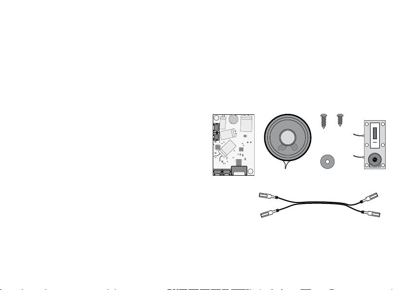
• Mount the speaker in the location specied for it
(Figure 2), using the 4 screws and spacers.
• Remove the mode of operation switch from the
locomotive and replace it with the circuit board
included with this kit. This circuit board has a mode of
operation switch and a volume controller.
• Connect the cable to the sound circuit board (Figure 4):
– Speaker as plugged into place
– Volume controller as plugged into place +-
– The cable included with the kit for supplying power
to the free pair of contacts is to be connected
either to the decoder or to the locomotive circuit
board (Figure 3)
– Plug in the reed switch if necessary ( )
• Using 2 screws, mount the sound circuit board in the
lower part of the locomotive (Figure 2).
• Check all of the mounting points and electrical con-
nections again, even those that you have not touched.
• Carefully re-assemble the locomotive. When doing
this make sure that no wires or cables are pinched.
Safety Notes
• This product may only be used with an operating
system designed for it.
• Use only switched mode power packs and transfor-
mers made for your local power system.
• Pay attention under all circumstances to the safety
notes in the instructions for your operating system.
• Not suitable for children under the age of 15.
• IMPORTANT! This product has sharp edges and
points related to its function.
Important Notes
• The operating instructions and the packaging are
component parts of this product and must be pre-
served as well as passed on to other parties taking
possession of this product.
• Information about disposal in Europe (German text):
www.maerklin.com/en/imprint.html
Functions
• This product is designed for operation in the 2x52x
series and comparable LGB diesel locomotives (DC,
0 – 24 volts).

10
Analog Operation
The sound will turn on when the track voltage is about
7 volts or more. The sounds are played back as long as
there is enough voltage in the track. The 65011 standing
sounds power supply module must also be installed and
connected for sound from a locomotive that is stopped
(Figure 4).
The horn or the whistle can also be activated with the
reed switches (Figure 4) that can be connected. This
activation is done with magnets laid in the track.
Digital Operation
The different sounds can be controlled in digital ope-
ration (see table “Controllable Functions“). The option
of having reed switches that can be connected to the
sound circuit boards (Figure 4) also allows you to activa-
te the horn or the whistle with magnets laid in the track.
This sound kit can be programmed like a locomotive
decoder. We recommend using the same address for the
locomotive decoder and for this kit.
Controllable Functions
Lighting
Sound: Horn 1
Sound: Whistle 2
Sound: Station announcement 3
Sound: Station announcement 4
Sound: Operating sounds 5
Sound: Sound on/off 6
Sound: Horn 7
Sound: Starting up the locomotive 9
Sound: Radiator water preheat device 10
Sound: Brake test 11
Sound: Safety valve 12
Sound: Ventilation 13
Sound: Mechanical tachometer 14
Sound: Brakes squealing 15

11
Register Assignment Range Factory
Setting
CV 1 Address 0 – 127 3
CV 7
Reset basic settings
Reset function settings
Reset button assignments & loops
Reset volumes
—
55
77
111
133
CV 17 Long address (long Byte) (CV29 Bit 5=1)
CV 18 Long address (short Byte) (CV29 Bit 5=1)
CV 29 Bit 2 = Mode of operation (digital / analog+digital)
Bit 5 = Short / long address
0/4
0/32 4
CV 49 Activating functions parallel / serial 0/1 0
CV 131
– 142 F button assignments for sounds 1 – 12 0 – 16
CV 151
– 162 Loop number for sounds 1 – 12 0 – 16 0
CV 200 Volume 8 (1=soft; 63=loud; 255=external controller) 1 – 63 / 255 32
CV 201
– 212 Volume for sounds 1 – 12 0 – 3 3

12
Ce kit supplémentaire est prévu pour équiper les
modèles LGB 2x52x ultérieurement avec du son. Toutes
les pièces nécessaires au montage sont jointes dans le
kit. Néanmoins, nous attirons votre attention sur le fait
que des connaissances électriques et mécaniques sur
le modélisme ferroviaire sont requises pour l’installation.
Nous n’assumerons aucune responsabilité pour tout
défaut ou détérioration dû à une installation inapprop-
riée.
Ce kit de rééquipement de son peut de plus être
complété par l’alimentation en courant pour bruit de
stationnement 65011. La trompe et les sifflets peuvent
aussi être couplés en plus via un interrupteur à lames
(69800, 65012).
Pour les connexions, veuillez vous reporter à
l’illustration 4.
1 x 1 x 4 x
2 x 4 x
1 x
1 x
Sommaire
Le kit se compose des parties suivantes :
• Carte de circuits «module son»
• Haut-parleur
• Carte de circuits «réglage du volume et commutateur
de fonctions»
• Câble pour l’alimentation en tension
• 6 x vis de xation & 4 x rondelles

13
Installation
• Ouvrez la locomotive et détachez le boîtier entière-
ment (ill. 1).
• Fixez le haut-parleur à l’aide de 4 vis et 4 rondelles à
l’endroit prévu (ill. 2).
• Ôtez le commutateur de fonctions de la locomotive
et remplacez-le par la carte de circuits ci-jointe avec
commutateur de fonctions et réglage du volume.
• Connectez les câbles à la carte de circuits de bruit (ill. 4).
– enchez le haut-parleur au symbole
– enchez le bouton de réglage du volume au symbo-
le +-
– Connectez le câble fourni pour l’alimentation en
courant à la paire de contacts libre, soit sur le
décodeur, soit sur la carte de circuits de la locomo-
tive (ill. 3)
– le cas échéant, enchez l’interrupteur à lames (
)
• xez la carte de circuits de bruit à l’aide de 2 vis dans
la partie inférieure de la locomotive (ill. 2).
• Vériez encore une fois toutes les xations et conne-
xions électriques, y inclus celles que vous n’avez pas
touchées.
• Remontez la locomotive avec précaution. Veillez à ce
qu’aucun câble ne soit coincé.
Avis de sécurité
• Le produit ne peut être utilisé qu’avec un système
d’exploitation prévu à cette n.
• Utiliser uniquement des composants secteur et des
transformateurs correspondant à votre tension de
réseau locale.
• Respectez impérativement les consignes de sécurité
données dans le mode d’emploi de votre système
d’exploitation.
• Le produit n’est pas adapté aux enfants en moins de
15 ans.
• ATTENTION ! Arêtes et pointes acérées fonctionnelles.
Remarques importantes
• Le mode d’emploi et l’emballage font partie intégrante
du produit et doivent de ce fait être conservés et
remis lors de toute cession du produit à un tiers.
• Mise au rebut : www.maerklin.com/en/imprint.html
Fonctions
• Le produit est prévu pour l’utilisation dans les locomo-
tives diesel LGB 2x52x et similaires (DC, 0 – 24 V).

14
Fonctionnement en mode analogique
Le son s’allume à partir d’une tension de la voie
d’environ 7 volts. Les bruits sont émis tant que la
tension reste sufsante. L’émission de bruits lorsque
la locomotive est à l’arrêt est par ailleurs conditionnée
à l’intégration et au branchement de l’alimentation en
courant pour bruit de stationnement 65011 (ill. 4).
Grâce aux interrupteurs à lames connectables en option
(ill. 4), la trompe ou le sifflet peuvent de plus être déclen-
chés par le biais d’aimants posés dans la voie.
Fonctionnement en mode numérique
En mode numérique, les différents bruits peuvent être
commutés (voir tableau «Fonctions commutables»).
Grâce aux interrupteurs à lames connectables en option
(ill. 4), la trompe ou le sifflet peuvent de plus être déclen-
chés par le biais d’aimants posés dans la voie.
Le kit de rééquipement de son peut être programmé tel
un décodeur de locomotive. Nous vous recommandons
d’utiliser la même adresse pour le décodeur de locomo-
tive et le kit de rééquipement.
Fonctions commutables
Eclairage
Bruit : trompe 1
Bruit : sifflet 2
Bruit : annonce de gare 3
Bruit : annonce de gare 4
Bruit : bruit de fonctionnement 5
Bruit : son allumé / éteint 6
Bruit : trompe 7
Bruit : préparation de la locomotive 9
Bruit : dispositif de préchauffage de l’eau
réfrigérante 10
Bruit : vérication des freins 11
Bruit : vanne de surpression 12
Bruit : purge 13
Bruit : tachymètre mécanique 14
Bruit : grincement des freins 15

15
Registre Affectation Plage ex usine
CV 1 Adresse 0 – 127 3
CV 7
Réinitialisation des réglages de base
Réinitialisation des réglages de fonctions
Réinitialisation des affectations de touches & boucles
Réinitialisation des volumes sonores
—
55
77
111
133
CV 17 Adresse longue (octet long) (CV29 Bit 5=1)
CV 18 Adresse longue (octet court) (CV29 Bit 5=1)
CV 29 Bit 2 = mode de fonctionnement (numérique / analogue+numérique)
Bit 5 = adresse longue / courte
0/4
0/32 4
CV 49 Déclenchement des fonctions parallèles / sérielles 0/1 0
CV 131
– 142 Affectation des touches de fonction bruits 1 - 12 0 – 16
CV 151
– 162 Nombre de boucles bruits 1 - 12 0 – 16 0
CV 200 Niveau du volume sonore 8 (1=faible ; 63=fort ; 255 = réglage externe) 1 – 63 / 255 32
CV 201
– 212 Niveau de volumes sonores bruits 1 - 12 0 – 3 3

16
Deze uitbreidingsset is bedoeld om de LGB modellen
2x52x van sound te voorzien. Alle benodigde delen
voor de inbouw zijn aanwezig in de set. Toch wijzen
we u er op dat elektrische en mechanische kennis van
een modelbaan noodzakelijk is voor het inbouwen. We
geven geen garantie op fouten of beschadigingen door
onzorgvuldige inbouw. Deze sound uitbreidingset kan
daarnaast nog uitgebreid worden met de standgeluid
stroomvoorziening 65011. De hoorn en de fluit kunnen
daarnaast ook door een reedcontact (69800, 65012)
geschakeld worden. De aansluitingen daarvan vindt u
in afb. 4.
1 x 1 x 4 x
2 x 4 x
1 x
1 x
Inhoud
De set bestaat uit de volgende delen:
• Printplaat “soundmodule“
• Luidspreker
• Printplaat “volumeregelaar en bedrijfssoorten scha-
kelaar“
• Kabel voor de stroomverzorging
• 6 x bevestigingsschroeven en 4 x opvulringen

17
Inbouw
• Open de loc en verwijder de lockap in zijn geheel
(afb.1)
• Bevestig de luidspreker met 4 schroeven en de 4
opvulringen op de aangegeven plaats (afb. 2).
• Verwijder de bedrijfssoorten schakelaar uit de loc en
vervang deze door de meegeleverde printplaat met de
bedrijfssoorten schakelaar en de volumeregelaar.
• Verbind de kabel met de sound printplaat (afb. 4):
- luidspreker insteken
- volumeregelaar insteken +-
- de meegeleverde kabel voor de stroomvoorziening
op het vrije contactenpaar, op de decoder of op de
locprintplaat, aansluiten (afb. 3)
- eventueel reedcontact ( ) insteken
• Bevestig de soundprintplaat met 2 schroeven op het
loc onderstel (afb. 2).
• Controleer alle bevestigingen en elektrische aanslui-
ting nog een keer, ook die u niet aangeraakt heeft.
• Zet de loc voorzichtig weer in elkaar. Let er daarbij op
dat er geen draden ingeklemd worden.
Veiligheidsvoorschriften
• Het product mag alleen met het daarvoor bestemde
bedrijfssysteem gebruikt worden.
• Alleen netadapters en transformatoren gebruiken die
geschikt zijn voor de plaatselijke netspanning.
• Lees ook de veiligheidsvoorschriften in de gebruik-
saanwijzing van uw bedrijfssysteem.
• Niet geschikt voor kinderen jonger dan 15 jaar.
• LET OP! Heeft vanwege de functionaliteit scherpe
kanten en punten.
Belangrijke aanwijzingen
• De gebruiksaanwijzing en de verpakking zijn
bestandsdelen van het product en dienen daarom be-
waard te worden en met het afgeven van het product
meegegeven te worden.
• Afdanken: www.maerklin.com/en/imprint.html
Werking
• Het product is bedoeld voor het bedrijf in de LGB die-
sellocomotieven 2x52x en de daarmee vergelijkbare
locs (DC 0 - 24V).

18
Analoog bedrijf
Vanaf een railspanning van ca. 7 Volt schakelt het geluid
in. De geluiden worden afgespeeld zolang er voldoende
spanning aanwezig is. Voor geluid bij stilstaande loco-
motieven moet de standgeluid stroomvoorziening 65011
extra ingebouwd en aangesloten worden (afb. 4).
Door de optioneel aansluitbare reedcontacten (afb. 4)
kunnen met de in de rails geplaatste magneten de hoorn
en fluit ingeschakeld worden.
Digitaal bedrijf
In het digitale bedrijf zijn de verschillende geluiden
schakelbaar (zie de tabel “schakelbare functies“). Door
de optioneel aansluitbare reedcontacten (afb. 4) kunnen
met de in de rails geplaatste magneten de hoorn en fluit
ingeschakeld worden.
De sound uitbreidingset kan net als een locdecoder
geprogrammeerd worden. Het is aan te bevelen om
de uitbreidingsset op hetzelfde adres als de loc te
gebruiken.
Schakelbare functies
Verlichting
Geluid: signaalhoorn 1
Geluid: fluit 2
Geluid: stations omroep 3
Geluid: stations omroep 4
Geluid: bedrijfsgeluid 5
Geluid: sound aan/uit 6
Geluid: signaalhoorn 7
Geluid: opstarten loc 9
Geluid: voorverwarming koelwater 10
Geluid: remproef 11
Geluid: overdrukventiel 12
Geluid: ontluchten 13
Geluid: mechanische tachograaf 14
Geluid: piepende remmen 15

19
Register Omschrijving Bereik Af fabriek
CV 1 Adres 0 – 127 3
CV 7
Reset basisinstelling
Reset functie instelling
Reset toetstoewijzing & loops
Reset volumes
—
55
77
111
133
CV 17 Langadres (lange byte) (CV29 bit 5=1)
CV 18 Langadres (korte byte) (CV29 bit 5=1)
CV 29 Bit 2 = bedrijfssysteem (digitaal/analoog)
Bit 5 = kort/lang adres
0/4
0/32 4
CV 49 Functies aansturen parallel / serieel 0/1 0
CV 131
– 142 Functietoetsen toewijzing sounds 1-12 0 – 16
CV 151
– 162 Loopaantal sounds 1-12 0 – 16 0
CV 200 Volume 8 (1=zacht; 63 = luid; 255 = externe regelaar) 1 – 63 / 255 32
CV 201
– 212 Volume sounds 1-12 0 – 3 3

20
Este kit de retroequipamiento ha sido concebido para
modernizar con sonido los modelos en miniatura LGB
2x52x. Todas las piezas necesarias para su montaje se
adjuntan en el set. A pesar de ello, se ha de recordar
que para el montaje se requieren conocimientos
eléctricos y mecánicos en modelismo ferroviario. No
asumimos ninguna responsabilidad por los errores y
daños que se produzcan como consecuencia de un
montaje inadecuado.
Este set de retroequipamiento de sonido puede comple-
mentarse adicionalmente con la alimentación eléctrica
de sonido de reposo 65011. Además, la bocina y el
silbato pueden maniobrarse adicionalmente mediante
un contacto reed (tipo lámina) (69800, 65012).
En la gura 4 encontrará las conexiones necesarias
para dicho contacto.
1 x 1 x 4 x
2 x 4 x
1 x
1 x
Contenido
El set incluye los siguientes componentes:
• Tarjeta de circuito impreso “Módulo de sonido“
• Altavoz
• Tarjeta de circuito impreso “Regulador de volumen y
selector de modo de funcionamiento“
• Cable de alimentación eléctrica
• 6 tornillos de jación y 4 arandelas
Table of contents
Languages:
Other LGB Toy manuals