manuals.online logo
Brands
  1. Home
  2. •
  3. Brands
  4. •
  5. LOVATO ELECTRIC
  6. •
  7. Control Unit
  8. •
  9. LOVATO ELECTRIC EXM 10 12 User manual

LOVATO ELECTRIC EXM 10 12 User manual

Doc: MHIT100A0608_EXM1012_20 28/07/2009 s. 1 / 5
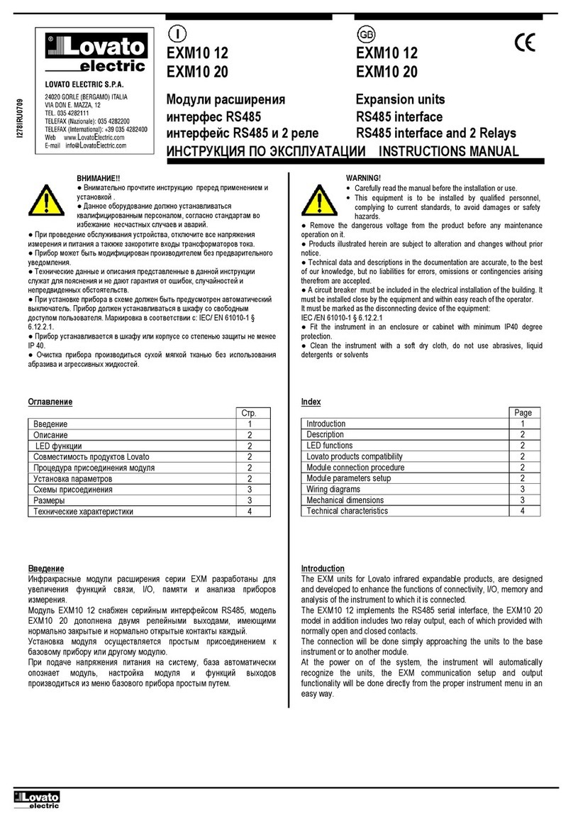
EXM10 12 EXM10 12
EXM10 20
EXM10 20
Moduł rozszerzeń Expansion units
Interfesj RS485 RS485 interface
Interfejs RS485 i 2 prze aźni i RS485 interface and 2 Relays
INSTRUKCJA OBSŁUGI
INSTRUCTIONS MANUAL
● Przed pracami serwisowymi, należy odłączyć wszystkie napięcia od wejść
pomiarowych i zasilania pomocniczego oraz zewrzeć zaciski przekładnika
prądowego.
● Prod kty zaprezentowane w poniższym dok mencie mogą zostać zmienione
l b lepszone bez konieczności wcześniejszego informowania o tym.
●
Dane techniczne oraz opisy oddają w jak najdokładniejszy sposób posiadaną
przez nas wiedzę, jednak nie bierzemy odpowiedzialności za ewent alne błędy,
braki oraz syt acje awaryjne.
● W kładzie należy zamontować rozłącznik (wyłącznik), który m si znajdować
się niedaleko rządzenia i być łatwo dostępny dla operatora. M si spełniać wymogi
następ jących norm: IEC/ EN 61010-1 § 6.12.2.1.
● Należy mieszczać rządzenie w ob dowie l b szafie o minimalnym stopni
ochrony IP40.
● Należy czyścić rządzenie delikatną s chą szmatką, nie należy żywać środków
ściernych, płynnych detergentów l b rozp szczalników.
● Remove the dangero s voltage from the prod ct before any maintenance
operation on it.
● Prod cts ill strated herein are s bject to alteration and changes witho t prior
notice.
● Technical data and descriptions in the doc mentation are acc rate, to the best
of o r knowledge, b t no liabilities for errors, omissions or contingencies arising
therefore are accepted.
● A circ it breaker m st be incl ded in the electrical installation of the b ilding. It
m st be installed close by the eq ipment and within easy reach of the operator.
It m st be marked as the disconnecting device of the eq ipment:
IEC /EN 61010-1 § 6.12.2.1
● Fit the instr ment in an enclos re or cabinet with minim m IP40 degree
protection.
● Clean the instr ment with a soft dry cloth, do not se abrasives, liq id
detergents or solvents
Spis treści
Strona
Wprowadzenie
1
Opis
2
F nkcje
sygnalizacji LED
2
Kompatybilność z prod ktami Lovato
2
Proced ra podłączenia mod ł
2
Ustawianie parametrów
2
Schematy podłączeń
3
Wymiary mechaniczne
3
Dane techniczne
4
Index
Page
Introd ction
1
Description
2
LED f nctions
2
Lovato prod
cts compatibility
2
Mod le connection proced re
2
Mod le parameters set p
2
Wiring diagrams
3
Mechanical
dimensions
3
Technical characteristics
4
Wprowadzenie
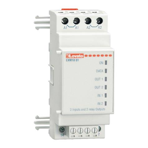
Mod ły EXM dedykowane są do prod któw z możliwością rozszerzenia
przez łącze podczerwieni i zostały zaprojektowane by zwiększyć
możliwość typ podłączenia, dostępnoćć wejść/wyjść i zapamiętywanie
i analizę pomiarów z rządzenia do którego jest podłączony.
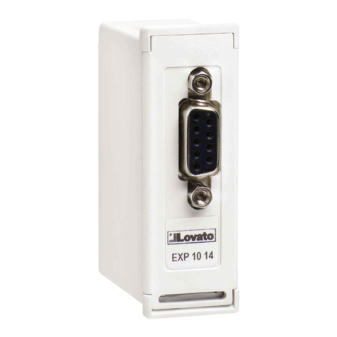
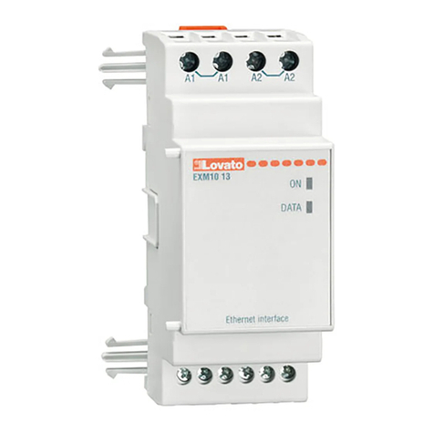
Mod ł EXM10 12 posiada interfejs RS485, mod ł EXM10 20 dodatkowo
posiada dwa wyjścia przekaźnikowe, każde z 1 zestykiem NO
i 1 zestykiem NC. Przyłączenia dokon je się szybko do jednostki bazowej
l b j ż zamontowanego mod ł .
Po podłączeni zasilania kład a tomatycznie rozpozna typ mod ł EXM,
stawienia kom nikacji i f nkcjonalności wyjść dokon je się w prosty
sposób z poziom men rządzenia.
Introduction
The EXM nits for Lovato infrared expandable prod cts, are designed
and developed to enhance the f nctions of connectivity, I/O, memory and
analysis of the instr ment to which it is connected.
The EXM10 12 implements the RS485 serial interface, the EXM10 20
model in addition incl des two relay o tp t, each of which provided with
normally open and closed contacts.
The connection will be done simply approaching the nits to the base
instr ment or to another mod le.
At
the power on of the system, the instr ment will a tomatically
recognize the nits, the EXM comm nication set p and o tp t
f nctionality will be done directly from the proper instr ment men in an
easy way.
I278PL
GB
07
09
UWAGA
!!
● Należy dokładnie zapoznać się z poniższa instr kcją przed
instalacją l b żywaniem rządzenia.
● By niknąć szkodzęń i zagrożenia życia rządzenia
te powinny być instalowane przez wykwalifikowany personel,
i w zgodzie z
odpowienimi przepisami.
WARNING!
• Caref lly read the man al before the installation or se.
• This eq ipment is to be installed by q alified personnel,
complying to c rrent standards, to avoid damages or safety
hazards.
Doc: MHIT100A0608_EXM1012_20 28/07/2009 s. 2 / 5
Opis
• Ob dowa mod łowa 2U (36mm) do montaż na szynie DIN
• Podwójny port podczerwieni
• Interfejs kom nikacji RS485 z prędkością przesył danych
do 38400Bps
• 32 węzły z programowalnymi ID od 0 do 255
• Wersja EXM10 12
•
2 wskaźniki LED
• Wersja EXM10 20
•
2 wyjścia przekaźnikowe
•
Zestyki NO i NC dla każdego przekaźnika
•
4 wskaźniki LED
• A tomatyczne rozpoznawanie przez jednostke bazową
• Ustawianie parametrów (COM i OUT) przez men rządzenia
Description
• Mod lar DIN-rail ho sing, 2U (36mm wide).
• Do ble infrared connection port
• RS485 serial interface with bitrates p to 38400Bps
• Up to 32 nodes with 0÷255 ID address programmable
• EXM10 12 version:
•
2 Indication LED
• EXM10 20 version:
•
2 Relay o tp ts
•
NO and NC o tp ts for every relay
•
4 Indication LED
• A tomatically recognition from the instr ment to which is connected
• EXM config ration from the proper instr ment men .
Fun cje sygnalizacji LED
KOD
KOLOR
OPIS
ON
Zielony
Włączony
:
Zasilanie włączone
Wyłączony:
Mod ł nie jest zasilony l b jest szkodzony
DATA
Czerwony
Wyłączony
:
Połączenie podczerwieni OK
Brak kom nikacji na RS485
Szybkie miganie
R ch danych na RS485
Miganie co 2 sekundy:
Problemy z połączeniem optycznym
OUT1
Czerwony
Wyłączony
:
Wyj przekaźnikowe 1 nieaktywne
Włączony: Wyj przekaźnikowe 1 aktywne
OUT2
Czerwony
Wyłączony
:
Wyj przekaźnikowe
2
nieaktywne
Włączony: Wyj przekaźnikowe 2 aktywne
LED functions
NA
ME
COLOR
D
ESCRI
PTION
ON
Green
Switched ON
:
Power s pply present on the nits
Switched OFF:
EXM is not powered or it is broken
DATA
Red
Switched OFF:
Infrared connection OK
No comm nication on the RS485
Fast blinking
Data traffic on the RS485 interface
Flashing at 2 seconds of eriod:
The mod le is not optically connected
OUT1
Red
Switched OFF:
Relay 1 o tp t not active
Switched ON: Relay 1 o tp t active
OUT2
Red
Switched OFF:
Relay 2
o tp t not active
Switched ON: Relay 2 o tp t active
Kompatybilność z produ tami Lovato
Mod ły rozszerzeń EXM10 12 i EXM10 20 mogą być podłączone
do wszystkich rządzeń Lovato posiadających możliwość kom nikacji
przez port podczerwieni
Lovato products compatibility
EXM10 12 and EXM10 20 expansion nits can be connected to any
Lovato prod ct fitted of optical infrared comm nication port.
Procedura podłączenia modułu
1. Odłączyć niebezpieczne napięcie.
2. Zamontować jednostkę na szynie DIN po prawej stronie jednostki
bazowej l b innego mod ł .
3. Należy przes nąć mod ł w kier nk jednostki bazowej l b innego
mod ł tak by klipsy montażowe znalazły się w całości w otworach
montażowych (sygnalizować to będzie kliknięcie).
4. Należy okablować rządzenie wedł g schemat podłączeń i podpiąć
zasilanie.
5. Włączyć zasilanie kład . Urządzenie np. DMG300 a tomatycznie
rozpozna typ mod ł .
6. Następnie należy skonfig rować mod ł zgodnie z instr kcją obsł gi.
Module connection procedure
1. Remove any dangero s voltage.
2. Insert the nits on the DIN rail g ide on the right side of the
instr ment or of another EXM.
3. Slide the mod le ntil the hooks presents on its box are f lly
inserted (for f ll incl sion feels a "click").
4. Follow the wiring diagram and connect the power s pply
cables.
5. Power p the system. The instr ments (e.g: DMG300) will
a tomatically recognize the expansion nits.
6. Config re the mod le by following the programming indication
presents on the instr ment man al.
DMG300 EXM10 1
2
/20
EXM10 .. EXM10 ..
o tional o tional
DMG300
EXM10
1
0
E
XM10 .. EXM10
o cja o cja
Doc: MHIT100A0608_EXM1012_20 28/07/2009 s. 3 / 5
BTR A
RELAY
NO
G
COM
RELAY
1 2
NC
COM NO NC
BG
ATR
Ustawianie parametrów modułu
W cel stawienia parametrów mod ł należy zapoznać się z instr kcją
główną rządzenia bazowego.
Module parameters setup
For the EXM parameters config ration, see the man al of the main
instr ment to which it intends to connect.
Schematy podłącz
e
ń
Wiring diag
rams
UWAGA: zaciski A1 i A1 są wewnętrznie połączone ze sobą,
tak samo zaciski A2 i A2. Wolne zaciski A1 i A2 są przeznaczone do
zasilania kolejne o modułu serii EXM (Max 3). Prąd maksymalny
500mA
ATTENTION: terminals A1 and A1 are internally connected
to ether and the same is for A2 and A2. The free terminals A1 and
A2 are only intended for the power supply of other EXM (Max 3.)
500mA maximum current
Schemat podłączenia
RS485
dla modułów
EXM10 12
i
EXM10 20
RS485 networ wiring diagram for EXM10 12 and EXM10 20 module
DEVICE 1......30
L MAX = 1200mt
DEVICE 31......60
L MAX = 1200mt
EXM10 ..
SET AS REPEATER
EIA-232 EIA-485/422
TR
B
TR
A
SG
CH2
A
B
SG
CH1
PX1
GTR BA
EXM10 ..
A1 A1 A2 A2
EXM10 ..
GTR A B
EXM10 ..
EIA-232
A1 A1 A2 A2
PC
RS232
RS232/RS485 CONV.
EIA-485/422
CH1
B
A
TR
CH2
SG
B
TR
A
SG
PX1
51C4
CABLE
TR
:
Przyłączenie do zacisk
rezystora.
Należy podłaczyć zacisk TR do A
w przypadk zastosowania rezystora
(120) pomiędzy liniami A i B.
EXM 10 ... EXM 10 ... EXM 10 ...
Kilka mod łów
Multi le connection
TR
: Termination resistor
Connect together TR and A in case
you want to insert termination resistor
(120
)
between lines A and B.
Podłączenie zacisków - Terminal connections
Doc: MHIT100A0608_EXM1012_20 28/07/2009 s. 4 / 5
Wymiary mechaniczne
Mechanical dimensions
Doc: MHIT100A0608_EXM1012_20 28/07/2009 s. 5 / 5
Wyjście prze aźni owe
(
tyl o
EXM10 20)
Output relays
(EXM10 20 only)
Dane techniczne
Technical characteristics
Zasilanie pomocnicze
Auxiliary supply
Napięcie znamionowe
Us
100
-
240V~
110 - 250V=
Nominal voltage Us
100
-
240V~
110 - 250V=
Zakres napięcia pracy
85
-
264V~
93,5 - 300V=
Operating voltage range
85
-
264V~
93,5 - 300V=
Częstotliwość
45
-
66Hz
Freq enc
y
45
-
66Hz
Pobór mocy/rozproszenie mocy
2VA
0,8W
Power cons mption/dissipation
2VA
0.8W
Czas odporności na mikroprzerwy
≥50ms
Imm nity time for microbreakings
≥50ms
Port
RS485
RS485 Serial interface
Prędkoś
ć przesył danych
programowalna
1200…38400 bps
Ba d
-
rate
1200…38400 bps programmable
Ilość wyjść
2
N mbe
r of o tp ts
2
Typ wyjścia
1
zestyk przełączny
Type of o tp t
1 changeover contact
Znamionowe napięcie pracy
250V~
Rated operating voltage
250V~
Wg
IEC/EN 60947
-
5
-
1
zestyk NO
zestyk NC
AC1 5A-250V~ 5A 30V=
AC1 2A-250V~ 2A 30V=
C300
IEC/EN 60947
-
5
-
1 designation
NO contact
NC contact
AC1 5A-250V~ 5A 30V=
AC1 2A-250V~ 2A 30V=
C300
Trwałość elektryczna
zestyk
NO
–
20x10
3
zadziałań
zestyk NC – 10x10
3
zadziałań
Electrical life
NO contact
–
20
x10
3
ops
NC contact – 10x10
3
ops
Trwałość mechaniczna
10
7
zadziałań
Mechanical life
10
7
ops
Warun i otoczenia
Ambient operating conditions
Temperat ra pracy
-
20
-
+60°C
Operating temperat re
-
20
-
+60°C
Temperat ra składowania
-
30
-
+80°C
Storage temp
erat re
-
30
-
+80°C
Wilgotność względna
<
90%
Relative h midity
<
90%
Maksymalny stopień zanieczyszczenia
stopień
2
Maxim m poll tion degree
Degree 2
Kategoria przeciążeniowa
3
Overvoltage category
3
Wysokość
≤2000m
Altit de
≤2000m
Napięcie izolacji
Insulation voltage
Znamionowe napięcie izolacji
Ui
250V~
Rated ins lation voltage Ui
250V~
Typ test
Uimp
AC test
Type of test
Uimp
AC test
Pomiędzy zasilaniem a
RS485
7,3kV
4kV
Between Pow
er S pply and RS485
7,3kV
4kV
Pomiędzy zasilaniem a wyjściami
7,3kV
4kV
Between Power S pply and O tp ts
7,3kV
4kV
Pomiędzy
RS485
a wyjściami
7,3kV
4kV
Between RS485 and O tp ts
7,3kV
4kV
Pomiędzy poszczególnymi wyjściami
4,8kV
1,5kV
Between the two relays o tp ts
4,8
kV
1,5kV
Podłączenie zasilania pomocniczego
Auxiliary supply connections
Typ zacisków
śr bowe
(
stałe
)
Terminal type
Screw (fixed)
Ilość zacisków
2 + 2
dla zasilania pomocniczego
N mber of terminals
2 + 2 for a x s pply
Przekrój przewod
(min
i
max)
0.2
-
4.
0 mm
2
(24 - 12 AWG)
Cable cross section (min… max)
0.2
-
4.0 mm
2
(24 - 12 AWG)
Moment obrotowy dokręcania
0,8Nm (7lbin)
Tightening torq e
0,8Nm (7lbin)
Podłączenie interfejsu
RS485
RS485 port connection
Typ zacisków
W
tykowe/
wyciągane
Terminal type
Pl g
-
in
/ removable
Ilość zacisków
4
N mber of terminals
4
Przekrój przewod
(min
i
max)
0,2...2,5 mmq (24
÷
12 AWG)
Cable cross section (min… max)
0.2…2.5 mm² (24…12 AWG)
Wg
UL
Przekrój przewod (min i max)
0,75...2.5 mm² (18
-
12
AWG)
UL Rating
Cable cross section (min… max)
0,75…2.5 mm² (18…12 AWG)
Moment obrotowy dokręcania
0,5 Nm (4,5 LBin)
Tightening torq e
0.5 Nm (4.5 lbin)
Podłączenie wyjść prze aźni owych
(
tyl o
EXM10 20)
Relay outputs connection (EXM10 20 only)
Typ zacisków
śr bowe
(
stałe
)
Termi
nal type
Screw (fixed)
Ilość zacisków
6
N mber of terminals
6
Przekrój przewod
(min
i
max)
0,2
-
2,5 mmq
(24 - 12 AWG)
Cable cross section (min… max)
0,2
-
2,5 mmq
(24 - 12 AWG)
Moment obrotowy dokręcania
0.44 Nm (4 lbin)
Tightening torq e
0.44 Nm (4 l
bin)
Obudowa
Housing
Wersja
2
mod ły
(DIN 43
880)
Version
2 mod les
(DIN 43880)
Montaż
Szyna
35mm (EN60715)
l b śr by (specjalne klipsy)
Mo nting
35mm DIN rail
(EN60715)
or by screw sing extractible clips
Materiał
Poliamid
RAL 7035
Material
Polyamide RAL7035
Stopień ochrony
IP40
od przod
IP20 zaciski
Degree of protection
IP40 on front
IP20 terminals
Masa
139
g
Weight
130
g
Uznania i normy
Certifications and compliance
Zgodne z normami
IEC/EN 61010
-
1:2001
, IEC/EN 61000
-
6
-
2:2005,
EN 61000-4-3:2006, EN 61000-6-3:2001,
IEC/EN 60068-2-61:1993, IEC/EN 60068-2-78,
IEC/EN 60068-2-6, IEC 60068-2-27, UL508,
C22.2-N°14-95.
Reference standards
IEC/EN 61010
-
1:2001, IEC/EN 61000
-
6
-
2:2005,
EN 61000-4-3:2006, EN 61000-6-3:2001,
IEC/EN 60068-2-61:1993, IEC/EN 60068-2-78,
IEC/EN 60068-2-6, IEC 60068-2-27, UL508,
C22.2-N°14-95.

This manual suits for next models

1

Other LOVATO ELECTRIC Control Unit manuals

LOVATO ELECTRIC EXP1013 User manual

LOVATO ELECTRIC

LOVATO ELECTRIC EXP1013 User manual

LOVATO ELECTRIC VLBXSM User manual

LOVATO ELECTRIC

LOVATO ELECTRIC VLBXSM User manual

LOVATO ELECTRIC RGAM User manual

LOVATO ELECTRIC

LOVATO ELECTRIC RGAM User manual

LOVATO ELECTRIC EXM10 13 User manual

LOVATO ELECTRIC

LOVATO ELECTRIC EXM10 13 User manual

LOVATO ELECTRIC EXP10 13 User manual

LOVATO ELECTRIC

LOVATO ELECTRIC EXP10 13 User manual

LOVATO ELECTRIC EXS0000 User manual

LOVATO ELECTRIC

LOVATO ELECTRIC EXS0000 User manual

LOVATO ELECTRIC EXP10 05 User manual

LOVATO ELECTRIC

LOVATO ELECTRIC EXP10 05 User manual

LOVATO ELECTRIC EXM10 11 User manual

LOVATO ELECTRIC

LOVATO ELECTRIC EXM10 11 User manual

LOVATO ELECTRIC RGK800 User manual

LOVATO ELECTRIC

LOVATO ELECTRIC RGK800 User manual

LOVATO ELECTRIC EXP10 02 User manual

LOVATO ELECTRIC

LOVATO ELECTRIC EXP10 02 User manual

LOVATO ELECTRIC EXM 10 01 User manual

LOVATO ELECTRIC

LOVATO ELECTRIC EXM 10 01 User manual

LOVATO ELECTRIC ATL DPS1 User manual

LOVATO ELECTRIC

LOVATO ELECTRIC ATL DPS1 User manual

LOVATO ELECTRIC RGK800SA User manual

LOVATO ELECTRIC

LOVATO ELECTRIC RGK800SA User manual

LOVATO ELECTRIC VLBX C Series User manual

LOVATO ELECTRIC

LOVATO ELECTRIC VLBX C Series User manual

LOVATO ELECTRIC EXP10 15 User manual

LOVATO ELECTRIC

LOVATO ELECTRIC EXP10 15 User manual

LOVATO ELECTRIC EXP10 10 User manual

LOVATO ELECTRIC

LOVATO ELECTRIC EXP10 10 User manual

LOVATO ELECTRIC EXP1016 User manual

LOVATO ELECTRIC

LOVATO ELECTRIC EXP1016 User manual

LOVATO ELECTRIC EXP10 03 User manual

LOVATO ELECTRIC

LOVATO ELECTRIC EXP10 03 User manual

LOVATO ELECTRIC EXP10 14 User manual

LOVATO ELECTRIC

LOVATO ELECTRIC EXP10 14 User manual

LOVATO ELECTRIC EXP10 12 User manual

LOVATO ELECTRIC

LOVATO ELECTRIC EXP10 12 User manual

LOVATO ELECTRIC GEX69 C Series User manual

LOVATO ELECTRIC

LOVATO ELECTRIC GEX69 C Series User manual

LOVATO ELECTRIC EXP10 30 User manual

LOVATO ELECTRIC

LOVATO ELECTRIC EXP10 30 User manual

LOVATO ELECTRIC RGK700 User manual

LOVATO ELECTRIC

LOVATO ELECTRIC RGK700 User manual

LOVATO ELECTRIC EXS4000 User manual

LOVATO ELECTRIC

LOVATO ELECTRIC EXS4000 User manual

Popular Control Unit manuals by other brands

RTS 810B Service manual

RTS

RTS 810B Service manual

ICP DAS USA LP-8 4 Series Update guide

ICP DAS USA

ICP DAS USA LP-8 4 Series Update guide

PA VB 200 quick start guide

PA

PA VB 200 quick start guide

Danfoss AMZ 112 Instruction

Danfoss

Danfoss AMZ 112 Instruction

Haier YR-H71 Service manual

Haier

Haier YR-H71 Service manual

Würth TARVOS-II user manual

Würth

Würth TARVOS-II user manual

H3C LSVM1S9810FAN user manual

H3C

H3C LSVM1S9810FAN user manual

CALEFFI 553 Series manual

CALEFFI

CALEFFI 553 Series manual

Pentair 2510 Service manual

Pentair

Pentair 2510 Service manual

Emerson Rosemount ET410 quick start guide

Emerson

Emerson Rosemount ET410 quick start guide

Genebre 2415 Installation, operation and maintenance manual

Genebre

Genebre 2415 Installation, operation and maintenance manual

AMX HPX-AV100-RGB+A installation guide

AMX

AMX HPX-AV100-RGB+A installation guide

Dräger RailGard-S1 Installation and operating manual

Dräger

Dräger RailGard-S1 Installation and operating manual

Texas Instruments LM76005QEVM user guide

Texas Instruments

Texas Instruments LM76005QEVM user guide

Ingersoll-Rand IC-PCM Product information

Ingersoll-Rand

Ingersoll-Rand IC-PCM Product information

Bpt GVV/200 US installation instructions

Bpt

Bpt GVV/200 US installation instructions

Telit Wireless Solutions JF2 Hardware user's guide

Telit Wireless Solutions

Telit Wireless Solutions JF2 Hardware user's guide

Xilinx Virtex-6 FPGA Hardware setup guide

Xilinx

Xilinx Virtex-6 FPGA Hardware setup guide

manuals.online logo
manuals.online logoBrands
  • About & Mission
  • Contact us
  • Privacy Policy
  • Terms and Conditions

Copyright 2025 Manuals.Online. All Rights Reserved.