Doc: I297PLGB 1110 26/11/2010 s. 1 / 12
PL
EXP10 14 EXP10 14
ModułrozszerzeńExpansion module
interfejs PROFIBUS® DP PROFIBUS® DP interface
INSTRUKCJA OBSŁUGI INSTRUCTIONS MANUAL
●Przed pracami serwisowymi, należy odłączyćwszystkie napięcia.
●Produkty zaprezentowane w poniższym dokumencie mogązostaćzmienione
lub ulepszone bez konieczności wcześniejszego informowania o tym.
●Dane techniczne oraz opisy oddająw jak najdokładniejszy sposób posiadaną
przez nas wiedzę, jednak nie bierzemy odpowiedzialności za ewentualne błędy,
braki oraz sytuacje awaryjne.
●Należy czyścićurządzenie delikatnąsuchąszmatką, nie należy używaćśrodków
ściernych, płynnych detergentów lub rozpuszczalników.
●Remove the dangerous voltage from the product before any maintenance
operation on it.
●Products illustrated herein are subject to alteration and changes without prior
notice.
●Technical data and descriptions in the documentation are accurate, to the best
of our knowledge, but no liabilities for errors, omissions or contingencies arising
therefore are accepted.
●Clean the instrument with a soft dry cloth, do not use abrasives, liquid
detergents or solvents
Wprowadzenie
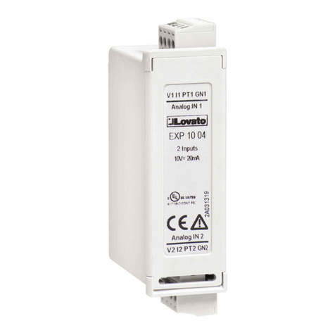
Moduły Lovato serii EXP dedykowane sądo produktów z możliwością
rozszerzenia przez gniazda wtykowe i zostały zaprojektowane
by zwiększyćmożliwość typu podłączenia, dostępnoćć wejść/wyjść
i zapamiętywanie i analizępomiarów z urządzenia do którego jest
podłączony. EXP1014 umożliwia podłączenie miernika przez port
PROFIBUS®. Może byćpodłączony do każdego z urządzeńLovato, które
wyposażone jest w gniazda wtykowe. Przyłączenia dokonuje sięszybko
do jednostki bazowej. Po podłączeniu zasilania układ automatycznie
rozpozna typ modułu EXP, a ustawieńmożna dokonać, w prosty sposób,
bezpośrednio z poziomu urządzenia bazowego.
Introduction
The EXP units for Lovato plug in expandable products are designed and
developed to enhance the functions of connectivity, I/O, memory and
analysis of the instrument to which it is connected.
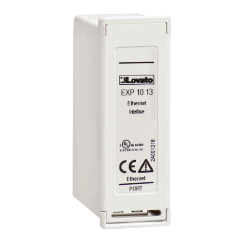
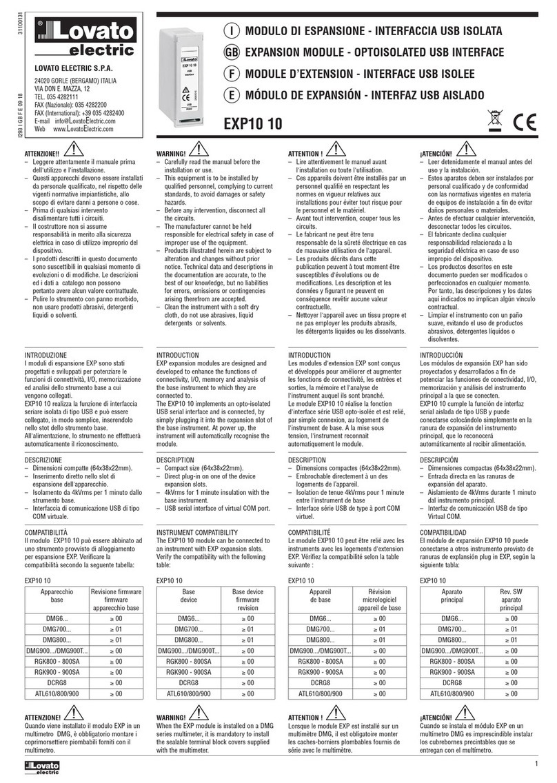
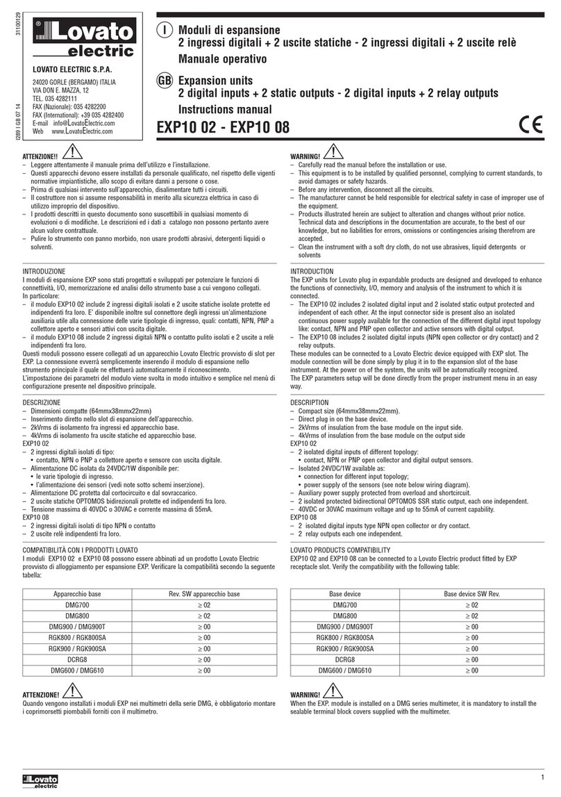
The EXP10 14 implements the isolated PROFIBUS® serial interface.
This module can be connected to a Lovato Electric device equipped with
EXP slot. The module connection will be done simply by plug it in to the
expansion slot of the base instrument. At the power on of the system, the
instrument will automatically recognize the units and the EXP parameters
setup will be done directly from the proper instrument menu in an easy
way.
Opis
Kompaktowe wymiary (64mmx38mmx22mm).
Podłączenie bezpośrednie, wtykowe, do urządzenia bazowego.
Izolacja od urządzenia bazowego: 2kVrms przez 1minutę.
PROFIBUS® DP (slave) do 12M.
Maksymalna ilość bajtów: 18 WEJŚCIE, 34 WYJŚCIE.
Automatyczny dobór prędkości przesyłu danych (9.600-19.200-
45.450-93.750-187.500-500.000-1.5M-3M-6M-12M bps)
Standardowa 9-pinowa wtyczka D-sub (damska).
Plik .GSD do pobrania z naszej strony www.lovatoelectric.com
Description
Compact size (64mmx38mmx22mm).
Direct plug in on the base instrument.
2KVrms for 1 minute of insulation from the base module.
PROFIBUS® DP slave, up to 12M.
Max number of exchange bytes 18 INPUT 34 OUTPUT.
Auto Baudrate (9.600-19.200-45.450-93.750-187.500-500.000-
1.5M-3M-6M-12M bps)
Standard 9-pin D-sub female connector.
File .GSD download available (www.lovatoelectric.com)
Kompatybilność z produktami Lovato
ModułrozszerzeńEXP10 14 może byćpodłączony do wszystkich
urządzeńLovato posiadających gniazda wtykowe. Należy sprawdzić
możliwość podłączenia danego modułu w instrukcji jednostki bazowej.
Jednostka bazowa Rewizja oprogramowania j.b.
DMG800 >= 07
DMG900 >= 04
Lovato products compatibility
EXP10 14 can be connected to a Lovato Electric product fitted by EXP
receptacle slot. Verify the compatibility with the following table:
Base device
Base device SW Rev.
DMG800
>= 07
DMG900
>= 04
I297PLGB 1110
UWAGA!!
●Należy dokładnie zapoznaćsięz poniższa instrukcjąprzed
instalacjąlub używaniem urządzenia.
●By uniknąć uszkodzeńi zagrożenia życia urządzenia
te powinny byćinstalowane przez wykwalifikowany personel,
i w z
odzie z od
owienimi
rze
isami.
WARNING!
Carefully read the manual before the installation or use.
This equipment is to be installed by qualified personnel,
complying to current standards, to avoid damages or safety
hazards.
UWAGA!
●Kiedy modułEXP jest zainstalowany na mierniku DMG
należy koniecznie zamontowaćosłonęzacisków
dostarczanąz miernikiem.
WARNING!
When the EXP. module is installed on a DMG series
multimeter, it is mandatory to install the sealable
terminal block covers supplied with the multimeter.
