manuals.online logo
Brands
  1. Home
  2. •
  3. Brands
  4. •
  5. LOVATO ELECTRIC
  6. •
  7. Control Unit
  8. •
  9. LOVATO ELECTRIC EXS0000 User manual

LOVATO ELECTRIC EXS0000 User manual


 
WARNING!

Carefully read the manual before the installation or use.

This equipment is to be installed by qualified personnel, complying to current standards, to
avoid damages or safety hazards.

Before any maintenance operation on the device, remove all the voltages from measuring and supply inputs and
short- circuit the CT input terminals.

The manufacturer cannot be held responsible for electrical safety in case of improper use of the equipment.

Products illustrated herein are subject to alteration and changes without prior notice. Technical data and
descriptions in the documentation are accurate, to the best of our knowledge, but no liabilities for errors, omissions
or contingencies arising there from are accepted.

A circuit breaker must be included in the electrical installation of the building. It must be installed close by the
equipment and within easy reach of the operator. It must be marked as the disconnecting device of the
equipment: IEC /EN 61010-1 § 6.11.3.1

Clean the device with a soft dry cloth; do not use abrasives, liquid detergents or solvents.
ATTENZIONE!

Leggere attentamente il manuale prima dell’utilizzo e l’installazione.

Questi apparecchi devono essere installati da personale qualificato, nel rispetto delle vigenti
normative impiantistiche, allo scopo di evitare danni a persone o cose.

Prima di qualsiasi intervento sullo strumento, togliere tensione dagli ingressi di misura e di alimentazione
e cortocircuitare i trasformatori di corrente.

Il costruttore non si assume responsabilità in merito alla sicurezza elettrica in caso di utilizzo improprio del dispositivo.

I prodotti descritti in questo documento sono suscettibili in qualsiasi momento di evoluzioni o di modifiche. Le
descrizioni ed i dati a catalogo non possono pertanto avere alcun valore contrattuale.

Un interruttore o disgiuntore va compreso nell’impianto elettrico dell’edificio. Esso deve trovarsi in stretta vicinanza
dell’apparecchio ed essere facilmente raggiungibile da parte dell’operatore. Deve essere marchiato come il
dispositivo di interruzione dell’apparecchio: IEC/ EN 61010-1 § 6.11.3.1.

Pulire l’apparecchio con panno morbido, non usare prodotti abrasivi, detergenti liquidi o solventi.
ATTENTION!

Lire attentivement le manuel avant toute utilisation et installation.

Ces appareils doivent être installés par un personnel qualifié, conformément aux normes en vigueur
en matière d'installations, afin d'éviter de causer des dommages à des personnes ou choses.

Avant toute intervention sur l'instrument, mettre les entrées de mesure et d'alimentation hors tension et court-
circuiter les transformateurs de courant.

Le constructeur n'assume aucune responsabilité quant à la sécurité électrique en cas d'utilisation impropre
du dispositif.

Les produits décrits dans ce document sont susceptibles d'évoluer ou de subir des modifications à n'importe
quel moment. Les descriptions et caractéristiques techniques du catalogue ne peuvent donc avoir aucune
valeur contractuelle.

Un interrupteur ou disjoncteur doit être inclus dans l'installation électrique du bâtiment. Celui-ci doit se trouver
tout près de l'appareil et l'opérateur doit pouvoir y accéder facilement. Il doit être marqué comme le dispositif
d'interruption de l'appareil : IEC/ EN 61010-1 § 6.11.3.1.

Nettoyer l’appareil avec un chiffon doux, ne pas utiliser de produits abrasifs, détergents liquides ou solvants.
ACHTUNG!

Dieses Handbuch vor Gebrauch und Installation aufmerksam lesen.

Zur Vermeidung von Personen- und Sachschäden dürfen diese Geräte nur von qualifiziertem
Fachpersonal und unter Befolgung der einschlägigen Vorschriften installiert werden.
UWAGA!

Przed u1yciem i instalacj&urz&dzenia nale1y uwa1nie przeczyta#niniejsz&instrukcj'.

W celu unikni'cia obra1e)osób lub uszkodzenia mienia tego typu urz&dzenia musz&by#
instalowane przez wykwalifikowany personel, zgodnie z obowi&zuj&cymi przepisami.

Przed rozpocz'ciem jakichkolwiek prac na urz&dzeniu nale1y od&czy#napi'cie od wej,# pomiarowych i
zasilania oraz zewrze#zaciski przekadnika pr&dowego.

Producent nie przyjmuje na siebie odpowiedzialno,ci za bezpiecze)stwo elektryczne w przypadku
niewa,ciwego u1ytkowania urz&dzenia.

Produkty opisane w niniejszym dokumencie mog&by#w ka1dej chwili udoskonalone lub zmodyfikowane.
Opisy oraz dane katalogowe nie mog&mie#w zwi&zku z tym 1adnej warto,ci umownej.

W instalacji elektrycznej budynku nale1y uwzgl'dni#prze&cznik lub wy&cznik automatyczny. Powinien on
znajdowa#si'w bliskim s&siedztwie urz&dzenia i by#atwo osi&galny przez operatora. Musi by#oznaczony jako
urz&dzenie su1&ce do wy&czania urz&dzenia: IEC/ EN 61010-1 § 6.11.3.1.

Urz&dzenie nale1y czy,ci#mi'kk&szmatk&, nie stosowa#,rodkow ,ciernych, pynnych detergentow lub rozpuszczalnikow.

Vor jedem Eingriff am Instrument die Spannungszufuhr zu den Messeingängen trennen und die Stromwandler
kurzschlie3en.

Bei zweckwidrigem Gebrauch der Vorrichtung übernimmt der Hersteller keine Haftung für die elektrische Sicherheit.

Die in dieser Broschüre beschriebenen Produkte können jederzeit weiterentwickelt und geändert werden. Die im
Katalog enthaltenen Beschreibungen und Daten sind daher unverbindlich und ohne Gewähr.

In die elektrische Anlage des Gebäudes ist ein Ausschalter oder Trennschalter einzubauen. Dieser muss sich in
unmittelbarer Nähe des Geräts befinden und vom Bediener leicht zugänglich sein. Er muss als Trennvorrichtung für
das Gerät gekennzeichnet sein: IEC/ EN 61010-1 § 6.11.3.1.

Das Gerät mit einem weichen Tuch reinigen, keine Scheuermittel, Flüssigreiniger oder Lösungsmittel verwenden.
ADVERTENCIA

Leer atentamente el manual antes de instalar y utilizar el regulador.

Este dispositivo debe ser instalado por personal cualificado conforme a la normativa de
instalación vigente a fin de evitar daños personales o materiales.

Antes de realizar cualquier operación en el dispositivo, desconectar la corriente de las entradas de
alimentación y medida, y cortocircuitar los transformadores de corriente.

El fabricante no se responsabilizará de la seguridad eléctrica en caso de que el dispositivo no se utilice de
forma adecuada.

Los productos descritos en este documento se pueden actualizar o modificar en cualquier momento. Por
consiguiente, las descripciones y los datos técnicos aquí contenidos no tienen valor contractual.

La instalación eléctrica del edificio debe disponer de un interruptor o disyuntor. Éste debe encontrarse cerca del
dispositivo, en un lugar al que el usuario pueda acceder con facilidad. Además, debe llevar el mismo marcado que
el interruptor del dispositivo (IEC/ EN 61010-1 § 6.11.3.1).

Limpiar el dispositivo con un trapo suave; no utilizar productos abrasivos, detergentes líquidos ni disolventes.
UPOZORNNÍ

Návod se pozorn(pro$t(te, nežza$nete regulátor instalovat a používat.

Tato za*ízení smí instalovat kvalifikovaní pracovníci v souladu s platnými p*edpisy a normami
pro p*edcházení úraz.osob $i poškození v(cí.

P*ed jakýmkoli zásahem do p*ístroje odpojte m(*icí a napájecí vstupy od nap(tí a zkratujte transformátory proudu.

Výrobce nenese odpov(dnost za elektrickou bezpe$nost v p*ípad(nevhodného používání regulátoru.

Výrobky popsané v tomto dokumentu mohou kdykoli projít úpravami $i dalším vývojem. Popisy a údaje uvedené v
katalogu nemají proto žádnou smluvní hodnotu.

Spína$$i odpojova$je nutno zabudovat do elektrického rozvodu v budov(. Musejí být nainstalované v t(sné
blízkosti p*ístroje a snadno dostupné pracovníku obsluhy. Je nutno ho ozna$it jako vypínací za*ízení p*ístroje:
IEC/ EN 61010-1 § 6.11.3.1.

P*ístroj $ist(te m(kkou ut(rkou, nepoužívejte abrazivní produkty, tekutá $istidla $i rozpoušt(dla.
AVERTIZARE!

Citi-i cu aten-ie manualul înainte de instalare sau utilizare.

Acest echipament va fi instalat de personal calificat, în conformitate cu standardele actuale,
pentru a evita deterior%ri sau pericolele.

Înainte de efectuarea oric%rei opera-iuni de între-inere asupra dispozitivului, îndep%rta-i toate tensiunile de la intr%rile
de m%surare "i de alimentare "i scurtcircuita-i bornele de intrare CT.

Produc%torul nu poate fi considerat responsabil pentru siguran-a electric%în caz de utilizare incorect%a
echipamentului.

Produsele ilustrate în prezentul sunt supuse modific%rilor "i schimb%rilor f%r%notificare anterioar%. Datele tehnice
"i descrierile din documenta-ie sunt precise, în m%sura cuno"tin-elor noastre, dar nu se accept%nicio r%spundere
pentru erorile, omiterile sau evenimentele neprev%zute care apar ca urmare a acestora.

Trebuie inclus un disjunctor în instala-ia electric%a cl%dirii. Acesta trebuie instalat aproape de echipament "i
într-o zon%u"or accesibil%operatorului. Acesta trebuie marcat ca fiind dispozitivul de deconectare al
echipamentului: IEC/EN 61010-1 § 6.11.3.1.

Cur%-a-i instrumentul cu un material textil moale "i uscat; nu utiliza-i substan-e abrazive, detergen-i lichizi sau
solven-i.
!

8K@A?@ R@G JKCLMNJ;MV E GIHM;AN CFC WELJFN;M;QCC NLMKIDLM=;, =HCG;M@FVHI IBH;EIGVM@LV L
I?@KA;HC@G H;LMIYT@>I KNEI=I?LM=;.

5I CB<@A;HC@ MK;=G CFC G;M@KC;FVHI>I NT@K<; GIHM;A ?IFA@H LNT@LM=FYMVLY MIFVEI E=;FCOCQCKI=;HHUG
J@KLIH;FIG = LIIM=@MLM=CC L ?@DLM=NXTCGC HIKG;MC=;GC.

8@K@? JKI=@?@HC@G FX<UP K;<IM JI M@PHCR@LEIGN I<LFNAC=;HCX NLMKIDLM=; H@I<PI?CGI I<@LMIRCMV =L@
CBG@KCM@FVHU@ C JCM;XTC@ =PI?HU@ EIHM;EMU, ; M;EA@ B;GEHNMV H;EIKIMEI =PI?HU@ EIHM;EMU
MK;HLOIKG;MIK; MIE; (99).

8KICB=I?CM@FV H@ H@L@M IM=@MLM=@HHILMV B; I<@LJ@R@HC@ WF@EMKI<@BIJ;LHILMC = LFNR;@ H@H;?F@A;T@>I
CLJIFVBI=;HCY NLMKIDLM=;.

6B?@FCY, IJCL;HHU@ = H;LMIYT@G ?IENG@HM@, = FX<ID GIG@HM GI>NM JI?=@K>HNMVLY CBG@H@HCYG CFC
NLI=@KS@HLM=I=;HCYG. 8IWMIGN E;M;FIAHU@ ?;HHU@ C IJCL;HCY H@ GI>NM K;LLG;MKC=;MVLY E;E
?@DLM=CM@FVHU@ L MIREC BK@HCY EIHMK;EMI=

:F@EMKCR@LE;Y L@MV B?;HCY ?IFAH; <UMV ILH;T@H; ;=MIG;MCR@LECG =UEFXR;M@F@G, EIMIKUD ?IFA@H <UMV
K;LJIFIA@H =<FCBC I<IKN?I=;HCY = JK@?@F;P ?ILMNJ; IJ@K;MIK;. 4=MIG;MCR@LECD =UEFXR;M@FV ?IFA@H
<UMV JKIG;KECKI=;H E;E IMEFXR;XT@@ NLMKIDLM=I I<IKN?I=;HCY: IEC /EN 61010-1 § 6.11.3.1.

7RCLMEN NLMKIDLM=; JKICB=I?CMV L JIGITVX GY>EID LNPID ME;HC, <@B JKCG@H@HCY ;<K;BC=HUP
G;M@KC;FI=, AC?ECP GIXTCP LK@?LM= CFC K;LM=IKCM@F@D.
DKKAT!

Montaj ve kullanımdan önce bu el kitabınıdikkatlice okuyunuz.

Bu aparatlar ki"ilere veya nesnelere zarar verme ihtimaline kar"ıyürürlükte olan sistem kurma
normlarına göre kalifiye personel tarafından monte edilmelidirler

Aparata (cihaz) herhangi bir müdahalede bulunmadan önce ölçüm giri"lerindeki gerilimi kesip akım
transformatörlerinede kısa devre yaptırınız.

Üretici aparatın hatalıkullanımından kaynaklanan elektriksel güvenli!e ait sorumluluk kabul etmez.

Bu dokümanda tarif edilen ürünler her an evrimlere veya de!i"imlere açıktır. Bu sebeple katalogdaki tarif ve
de!erler herhangi bir ba!layıcıde!eri haiz de!ildir.

Binanın elektrik sisteminde bir anahtar veya "alter bulunmalıdır. Bu anahtar veya "alter operatörün kolaylıkla
ula"abilece!i yakın bir yerde olmalıdır. Aparatı(cihaz) devreden çıkartma görevi yapan bu anahtar veya "alterin
markası: IEC/ EN 61010-1 § 6.11.3.1.

Aparatı(cihaz) sıvıdeterjan veya solvent kullanarak yumu"ak bir bez ile siliniz a"ındırıcıtemizlik ürünleri kullanmayınız
MODULES FOR EASY BRANCH SYSTEM – COMMUNICATION BUS
Instruction manual
MODUY DO SYSTEMU EASY BRANCH – MAGISTRALA KOMUNIKACYJNA
Instrukcja obsugi
EXS0000
2
 
INTRODUCTION
EXS0000 is an expansion module for DMG7500, DMG8000 and DMG9000 power analyzers which
lets the connection and powering of up to 8 EXS4... current measurement modules by using a
standard ethernet cable (cat.6), creating the communication bus of the EASY BRANCH system by
adding to the three-phase load already present in the DMG up to further 32 three-phase loads or 96
single-phase loads or in mixed configuration. Through the EXS0000 module, all the data of the EASY
BRANCH system are collected by the power analyzer and made available to the user via the color
display and the RS485 or ethernet communication port. The module also lets the connection of a
24VDC power supply which is necessary when the current modules are 5 or more.
WPROWADZENIE
EXS0000 jest to modurozszerze)dla analizatorów sieci DMG7500, DMG8000 i DMG9000, który
pozwala na pod&czenie oraz zasilanie – przy u1yciu standardowego kabla ethernet (kat. 6) –
maksymalnie 8 moduów pomiaru pr&du EXS4..., tworz&c – po dodaniu do obci&1enia trójfazowego
wyst'puj&cego ju1w DMG nawet 32 dodatkowych obci&1e)trójfazowych lub 96 obci&1e)
jednofazowych lub w konfiguracji mieszanej – magistral'komunikacyjn&systemu EASY BRANCH.
Poprzez moduEXS0000 wszystkie dane systemu EASY BRANCH s&gromadzone przez analizator
sieci i udost'pniane przez niego u1ytkownikowi poprzez kolorowy wy,wietlacz oraz port komunikacji
typu RS485 lub ethernet. Moduten pozwala równie1na pod&czenie zasilacza 24 V DC, który
okazuje si'konieczny, gdy moduów pr&dowych jest 5 lub wi'cej.
DESCRIPTION

Expansion module for the EASY BRANCH monitoring system.

Compatible with DMG7500, DMG8000, DMG9000.

Power supply: from the base device up to 4 current measure modules EXS4…, from external
24VDC@200mA otherwise.

RJ45 type bus connector.

Total length of the communication bus: 20m.
OPIS

Modurozszerze)dla systemu monitorowania EASY BRANCH.

Kompatybilny z DMG7500, DMG8000, DMG9000.

Zasilanie: z urz&dzenia bazowego do 4 moduów pomiaru pr&du EXS4…, w przeciwnym razie
24VDC@200mA z zewn&trz.

Z&cze magistrali typu RJ45.

Dugo,# cakowita magistrali komunikacyjnej: 20 m.
EXPANDABILITY
DMGs are equipped with 3 slots to add the modules of the EXP… series up to a maximum of 3
modules. EXS0000 must be inserted into expansion
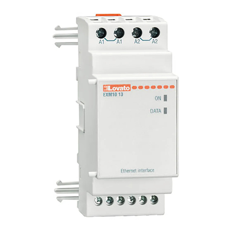
slot 3.
To insert an expansion module:

disconnect the power supply of DMG;

remove the terminal cover and the removable 9-pole
terminal block;

remove the protective cover of the expansion slot 3;

insert the upper hook of the module into the
appropriate hole;

rotate the module downwards inserting the connector on the bus;

press until the clip on the underside of the module snaps into place;

re-install the terminal block and the terminal cover.

When a DMG is powered on, it automatically recognizes the EXS0000 module connected to it. If the
system configuration is different from the last one detected, the base unit asks the user for
confirming the new configuration. In case of confirmation, the new configuration is saved and
becomes effective, otherwise the discrepancy will be signaled at each power up.

The current system configuration is displayed on the appropriate display page (expansion
modules), verify if the module has been correctly recognized.
MO0LIWO+CI ROZBUDOWY
DMG s&wyposa1one w 3 gniazda rozszerze)pozwalaj&ce na dodawanie moduów z serii EXP…
Maksymalnie mo1na doda#3 moduy. ModuEXS0000
naley podczado gniazda nr 3.
Aby pod&czy#modurozszerze), nale1y:

od&czy#zasilanie od DMG;

wyj&# oson'zacisków i wyjmowan&9-polow&listw'
zaciskow&;

wyj&# pokryw'zabezpieczaj&c&gniazdo nr 3;

wo1y#zaczep górny moduu w odpowiedni otwór;

obróci#moduw dó, pod&czaj&c z&cze do magistrali;

nacisn&# do momentu, a1specjalny zacisk w dolnej cz',ci moduu zostanie zatrza,ni'ty;

zainstalowa#na miejscu listw'zaciskow&i prze/roczyst&oson'zacisków.

Po pod&czeniu zasilania DMG automatycznie rozpoznaje pod&czony do niego moduEXS0000.
Je,li konfiguracja systemu jest inna od ostatnio rozpoznanej, jednostka gówna za1&da od
u1ytkownika potwierdzenia jej. W przypadku potwierdzenia nowa konfiguracja zostanie
zapami'tana i b'dzie dziaa#. W przeciwnym razie przy ka1dym ponownym uruchomieniu b'dzie
sygnalizowana niezgodno,#.

Aktualna konfiguracja systemu wy,wietlana jest na specjalnej stronie wy,wietlacza (moduy
rozszerze)): sprawdzi#, czy moduzostaprawidowo rozpoznany.
MECHANICAL DIMENSIONS, POSITION AND WIRING DIAGRAM WYMIARY MECHANICZNE, ZACISKI I SCHEMATY ELEKTRYCZNE
The bus cable must be installed inside an electrical conduit dedicated to cables with non-hazardous
voltage. Since the EASY Branch system is based on the assumption that the voltage measurement
values read by the power analyzer are valid at each measurement point, the installation of the entire
system should be inside the same electrical panel.
If connected, the external voltage must come from a double insulated, CAT III, 300V power supply.
Przewód magistrali powinien by#instalowany w specjalnym korytku przeznaczonym dla przewodów
bez niebezpiecznego napi'cia. System EASY Branch bazuje na zao1eniu, 1e warto,ci pomiaru
napi'cia odczytywane przez analizator sieci s&wa,ciwe w ka1dym punkcie pomiarowym, instalacja
caego systemu powinna znajdowa#si'wewn&trz tej samej szafy sterowniczej.
W przypadku pod&czenia napi'cia zewn'trznego, przewód w podwójnej izolacji musi spenia#
parametry dla CAT II 300V.
TECHNICAL CHARACTERISTICS PARAMETRY TECHNICZNE
Auxiliary power supply Zasilanie pomocnicze
Rated voltage Us 24V = Napi'cie znamionowe Us 24 V =
Operating voltage range 20.4…27.6V = Zakres cz'stotliwo,ci pracy 20,4…27,6 V =
Max current 200mA Pr&d maksymalny 200 mA
Ambient conditions Warunki otoczenia
Operating temperature Min -20°C – Max +60°C Temperatura pracy Min. - 20°C – maks. + 60°C
Storage temperature Min -30°C – Max +80°C Temperatura skadowania Min. - 30°C – maks. + 80°C
Relative humidity <80% (IEC/EN 60068-2-78) Wilgotno,# wzgl'dna <80% (IEC/EN 60068-2-78)
Maximum pollution degree 2 Maksymalny stopie)zanieczyszczenia 2
Overvoltage category III Kategoria przeci&1eniowa III
Climatic sequence Z/ABDM (IEC/EN 60068-2-61) Sekwencja klimatyczna Z/ABDM (IEC/EN 60068-2-61)
Shock resistance 10g (IEC/EN 60068-2-27) Odporno,# na uderzenia 10 g (IEC/EN 60068-2-27)
Vibration resistance 0.7g (IEC/EN 60068-2-6) Odporno,# na wibracje 0,7 g (IEC/EN 60068-2-6)
Connections Podczenie
Type of terminals Power supply: screw (removable), 2 terminals
Bus: RJ45 (max total length = 20m)
Typ zacisków Zasilanie: ,rubowe (wyci&gane), 2 zaciski
Magistrala: RJ45 (dugo,# cakowita = 20 m)
Conductor cross section (min and max) 0,2 - 2,5 mmq (24 - 12 AWG) Przekrój przewodów (min. i maks.) 0,2 - 2,5 mm2 (24 - 12 AWG)
Tightening torque 0,5 Nm (4.5 lbin) Moment dokr'cenia zacisków 0,5 Nm (4,5 lbin)
GNIAZDO
NR 3
+ -
24= 0
SLOT 3
External 24V= supply only needed
in case of more than 4 EXS4…
modules.
Zasilanie zewn'trzne 24=
wymagane tylko, je,li korzysta si'
z ponad 4 moduów EXS4…
3
 
Housing Obudowa
Material Polyamide RAL 7035 MateriaPoliamid RAL 7035
Dimensions 38 x 65 x 47 mm Wymiary d. x wys. x g. 38 x 65 x 47 mm
Protection degree IP20 Stopie)ochrony IP20
Weight 0.090 kg Masa 0 090kg
Certification and compliance Certyfikaty i normy
Certification CE, UKCA Certyfikaty CE, UKCA
Compliance IEC/EN/BS 61010-1, IEC/EN/BS 61000-6-2, IEC61000-6-4 Zgodno,# z normami IEC/EN/BS 61010-1, IEC/EN/BS 61000-6-2,
IEC61000-6-4

Other LOVATO ELECTRIC Control Unit manuals

LOVATO ELECTRIC VLBXSM User manual

LOVATO ELECTRIC

LOVATO ELECTRIC VLBXSM User manual

LOVATO ELECTRIC RGK800 User manual

LOVATO ELECTRIC

LOVATO ELECTRIC RGK800 User manual

LOVATO ELECTRIC EXP10 15 User manual

LOVATO ELECTRIC

LOVATO ELECTRIC EXP10 15 User manual

LOVATO ELECTRIC EXS4000 User manual

LOVATO ELECTRIC

LOVATO ELECTRIC EXS4000 User manual

LOVATO ELECTRIC EXP1013 User manual

LOVATO ELECTRIC

LOVATO ELECTRIC EXP1013 User manual

LOVATO ELECTRIC EXS4000 User manual

LOVATO ELECTRIC

LOVATO ELECTRIC EXS4000 User manual

LOVATO ELECTRIC VLBX C Series User manual

LOVATO ELECTRIC

LOVATO ELECTRIC VLBX C Series User manual

LOVATO ELECTRIC EXP10 02 User manual

LOVATO ELECTRIC

LOVATO ELECTRIC EXP10 02 User manual

LOVATO ELECTRIC EXP10 30 User manual

LOVATO ELECTRIC

LOVATO ELECTRIC EXP10 30 User manual

LOVATO ELECTRIC EXP10 15 User manual

LOVATO ELECTRIC

LOVATO ELECTRIC EXP10 15 User manual

LOVATO ELECTRIC EXP10 31 User manual

LOVATO ELECTRIC

LOVATO ELECTRIC EXP10 31 User manual

LOVATO ELECTRIC DCTL Series User manual

LOVATO ELECTRIC

LOVATO ELECTRIC DCTL Series User manual

LOVATO ELECTRIC EXP10 30 User manual

LOVATO ELECTRIC

LOVATO ELECTRIC EXP10 30 User manual

LOVATO ELECTRIC DCTL Series User manual

LOVATO ELECTRIC

LOVATO ELECTRIC DCTL Series User manual

LOVATO ELECTRIC EXP10 05 User manual

LOVATO ELECTRIC

LOVATO ELECTRIC EXP10 05 User manual

LOVATO ELECTRIC EXP10 14 User manual

LOVATO ELECTRIC

LOVATO ELECTRIC EXP10 14 User manual

LOVATO ELECTRIC EXP10 16 User manual

LOVATO ELECTRIC

LOVATO ELECTRIC EXP10 16 User manual

LOVATO ELECTRIC EXP10 13 User manual

LOVATO ELECTRIC

LOVATO ELECTRIC EXP10 13 User manual

LOVATO ELECTRIC EXM1013 User manual

LOVATO ELECTRIC

LOVATO ELECTRIC EXM1013 User manual

LOVATO ELECTRIC EXP1014 User manual

LOVATO ELECTRIC

LOVATO ELECTRIC EXP1014 User manual

LOVATO ELECTRIC EXM10 12 User manual

LOVATO ELECTRIC

LOVATO ELECTRIC EXM10 12 User manual

LOVATO ELECTRIC RGAM User manual

LOVATO ELECTRIC

LOVATO ELECTRIC RGAM User manual

LOVATO ELECTRIC EXM 10 12 User manual

LOVATO ELECTRIC

LOVATO ELECTRIC EXM 10 12 User manual

LOVATO ELECTRIC EXP10 10 User manual

LOVATO ELECTRIC

LOVATO ELECTRIC EXP10 10 User manual

Popular Control Unit manuals by other brands

Enerpac VSP Series instruction sheet

Enerpac

Enerpac VSP Series instruction sheet

C&H Technologies VX462B user manual

C&H Technologies

C&H Technologies VX462B user manual

GSD W2TM2510 user manual

GSD

GSD W2TM2510 user manual

Evenlite ELCD Installation & operation manual

Evenlite

Evenlite ELCD Installation & operation manual

Digital deep sea DSE5220 operating manual

Digital deep sea

Digital deep sea DSE5220 operating manual

System Sensor MDl Series Installation and maintenance instructions

System Sensor

System Sensor MDl Series Installation and maintenance instructions

Hillstone SG-6000 X-Series reference guide

Hillstone

Hillstone SG-6000 X-Series reference guide

Waves MDMX Screamer user guide

Waves

Waves MDMX Screamer user guide

BERMAD 420 maintenance

BERMAD

BERMAD 420 maintenance

NSK ASTRO-E 250 Operation manual

NSK

NSK ASTRO-E 250 Operation manual

Dickey-John Land Manager SE manual

Dickey-John

Dickey-John Land Manager SE manual

KSB BOAX-B Series operating instructions

KSB

KSB BOAX-B Series operating instructions

Olympia P-240XB Installation

Olympia

Olympia P-240XB Installation

Danfoss VHX-DUO Mounting guide

Danfoss

Danfoss VHX-DUO Mounting guide

Arduino Nano 33 BLE Rev2 Product reference manual

Arduino

Arduino Nano 33 BLE Rev2 Product reference manual

Emerson SAPAG Installation & maintenance instructions

Emerson

Emerson SAPAG Installation & maintenance instructions

TP-Link DS-PMA-C+ V1 installation guide

TP-Link

TP-Link DS-PMA-C+ V1 installation guide

Quectel GNSS Module Series user guide

Quectel

Quectel GNSS Module Series user guide

manuals.online logo
manuals.online logoBrands
  • About & Mission
  • Contact us
  • Privacy Policy
  • Terms and Conditions

Copyright 2025 Manuals.Online. All Rights Reserved.