Ltech LM-240-24-G2D2 User manual

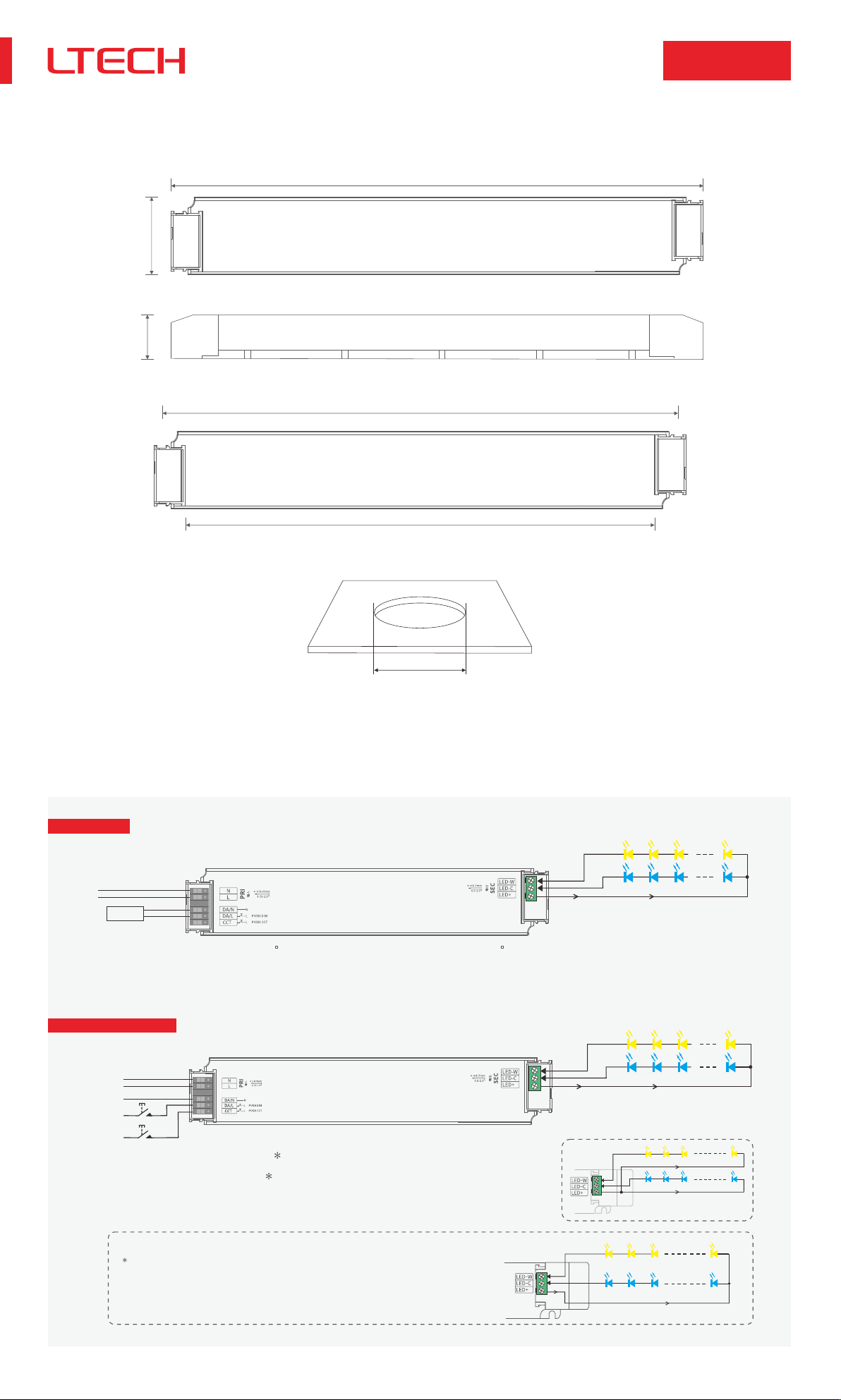
Intelligent Tunable White LED Driver (Constant Voltage)
LM-240-24-G2D2 DALI DT6/DT8
PUSH DIM/CCT
1
DIM/CCT
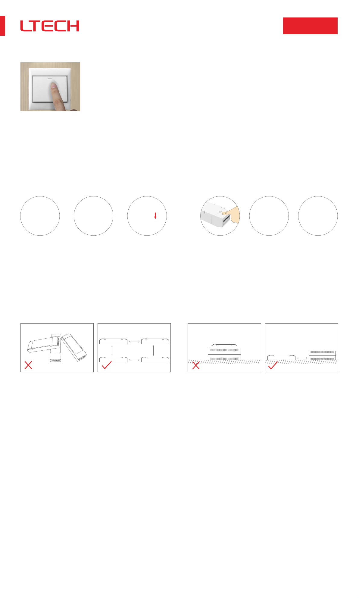
The housing is made from V0 flame retardant PC materials
from SAMSUNG/COVESTRO.
The clamshell design and screwless type for strain-relief.
The design of dismountable end cap allows you to adjust
the length of housing depending on your needs.
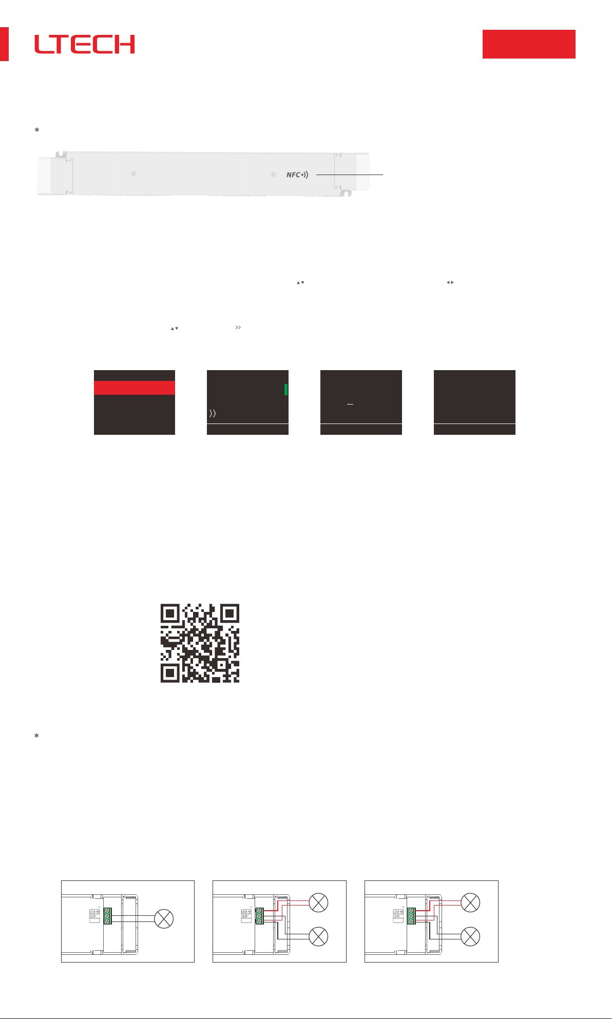
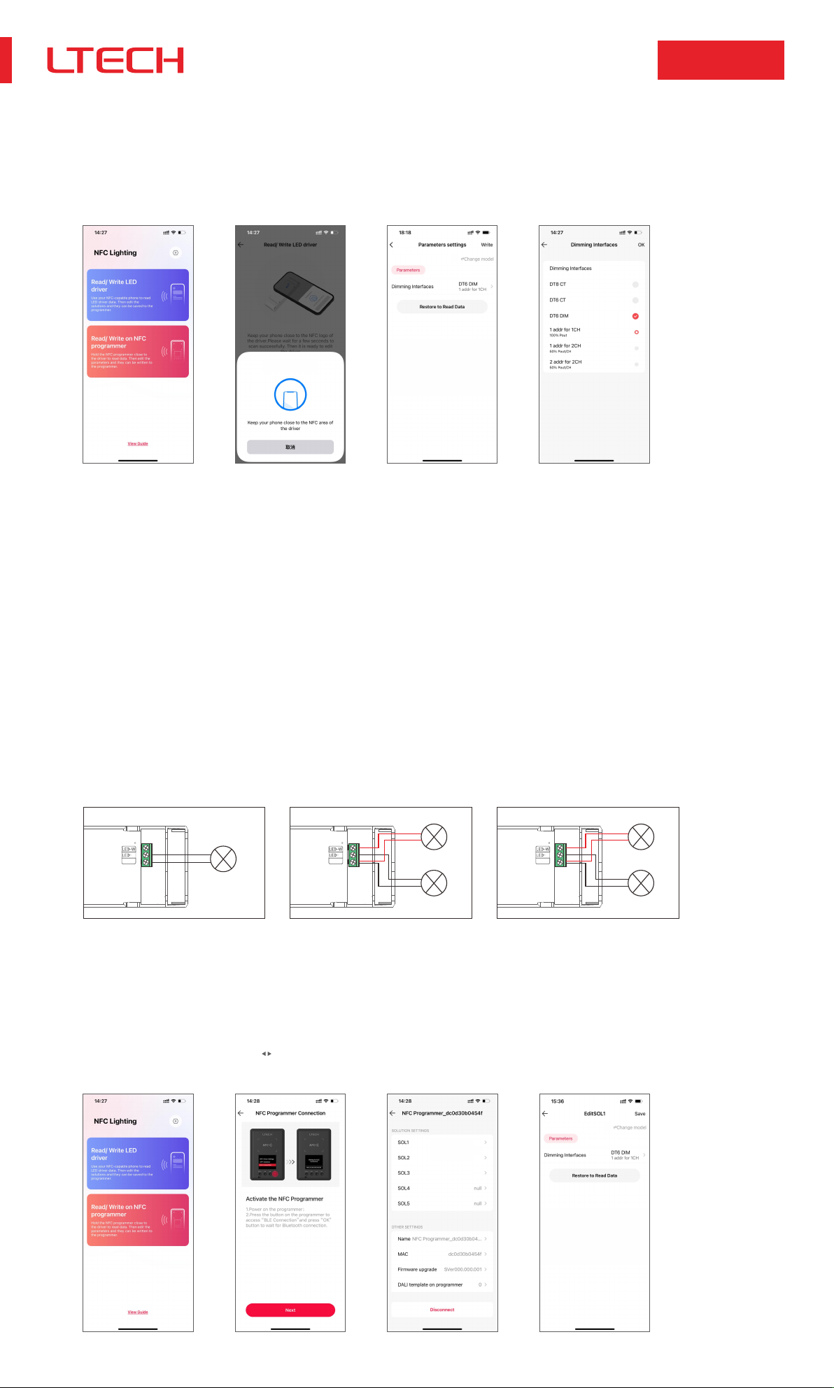
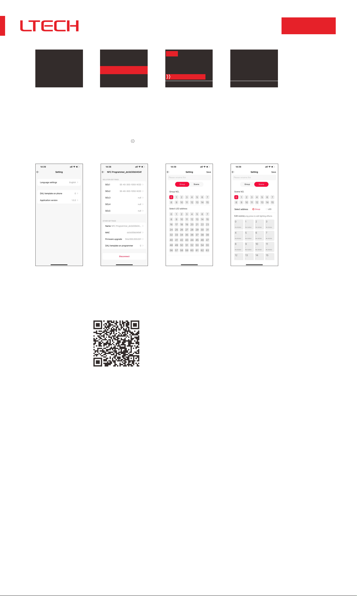
Change the dimming interface, DALI address and other
parameters on the NFC programmer or via the App, and
sync the parameters to the driver.
DALI bus standard IEC62386-101, 102, 209.
Class 2 LED driver, Safety Extra Low Voltage (SELV).
With soft-on and fade-in dimming function, enhancing your
visual comfort.
The whole dimming process is flicker-free with high frequency
exemption level.
Dimming from 0-100%, down to 0.01%.
Comply with the EU’s ErP Directive, networked standby<0.5W.
Overheat, over voltage, overload, short circuit protection and
automatic recovery.
Normal service life can reach 100,000 hours.
5-year warranty (Rubycon capacitor).
Adopt constant power design that can adjust different color
temperature while brightness remains the same.
The certification icon represents undergoing certification applications only, and final certification qualification subject to actual product.
Overheat
Protection ShortCircuit
Protection
Overload
Protection
V
Overvoltage
Protection
power program
design
Technical Specs
50/60Hz
Max. 1.18A/230Vac
94%
ta: -20~45°Ctc: 86°C
-40~80°C/10~95%RH
±0.03%/°C(0-50°C)
PF>0.99/230Vac, atfullload
THD≤5%/230Vac, atfullload
L-N: 2KV
Max. 0.5mA
LM-240-24-G2D2
24Vdc±0.5Vdc
OutputCurrent Max. 10A
24Vdc
Max. 240W
±5%
Shut down the output when non-load voltage≥28V, and recover automatically
Intelligently adjust or turn off the output current if the PCB temperature ≥110°C, and recover automatically
≤3600Hz
EN61000-4-2,3,4,5,6,8,11, EN61547
GB19510.1, GB19510.14
EN61347-1, EN61347-2-13, EN62384
KC61347-1, KC61347-2-13
IEC61347-1, IEC61347-2-13
EN61347-1, EN61347-2-13, EN62493
IEC61347-1, IEC61347-2-13
CCC
CE
KC
EAC
TUV
CB
RCM AS61347-1, AS61347-2-13
ENEC EN61347-1, EN61347-2-13, EN62384
CCC
CE
KC
EAC
GB/T17743, GB17625.1
EN55015, EN61000-3-2, EN61000-3-3, EN61547
KSC 9815, KSC 9547
IEC62493, IEC61547, EH55015
RCM EN55015, EN61000-3-2, EN61000-3-3, EN61547
IP20
DALIDT6/DT8, PUSHDIM/CCT
220-240Vac
198-264Vac
200-280Vdc
Ripple(maximum)
200mVp-p
UKCA BS EN 61347-1, BS EN 61347-2-13, BS EN 62493
555g±10g
380×49.5×30mm(L×W×H)
UKCA BS EN IEC 55015, BS EN IEC 61000-3-2, BS EN 61000-3-3, BS EN 61547
Shut down the output when rated power≥102-125%, auto recovers
ENVIRONMENT
Model
INPUT
PROTECTION
SAFETY
&
EMC
OUTPUT
ErP
OTHERS
Features
Dimming Interface
Output Feature
Output Type
Protection Grade
Insulation Grade
Isolation
Constant voltage
Class II (Suitable for class I/ II /III light fixtures)
Dimming Range
Output Voltage
Output Power
Current Accuracy
PWM Frequency
Output Voltage Range
0~100%, down to 0.01%
Frequency
Input Current
Efficiency (Typ.)
Power Factor
THD
Inrush Current
Anti Surge
Input Voltage
DC Voltage Range
AC Voltage Range
Leakage Current
Cold start 55A(Test twidth=1200us tested under 50% Ipeak)/230Vac
Working Temperature
Working Humidity
Storage Temperature/Humidity
Temperature Coefficient
Vibration
Overvoltage Protection
Overload Protection
Short Circuit Protection
Overheat Protection
Insulation Resistance
Withstand Voltage
SafetyStandards
EMC Emission
EMC Immunity
Power Consumption
Flicker/Stroboscopic Effect
DF
Dimensions
Weight(N.W.)
20~95%RH,non-condensing
10~500Hz, 2G 12min/1cycle, 72 min for X, Y and Z axes respectively
Enter hiccup mode if short circuit occurs, and recover automatically
I/P-O/P: 100MΩ/500VDC/25°C/70%RH
I/P-O/P: 3750Vac
China
European Union
Korea
Russia
Germany
CB Member States
Australia
Europe
Britain
China
European Union
Korea
Russia
Australia
Britain
Standby power consumption
Networked standby
No-load power consumption
IEEE1789
CIE SVM
Phase factor
Meet IEEE 1789 standard/High frequency exemption level
Pst LM≤1.0,SVM≤0.4
No standby mode
DF0.9
≤
≤0.5W (After shutdown by command)
≤0.5W (When the lamp is not connected)

2
连接应⽤图
W
-
-
+
+
C
Four-wire LED connection.
Adopting constant power program design, it keeps the same brightness in color temperature
dimming, twice the rated power load can be connected.
W
C
Max. 240W
Max. 240W
N
DALI
L
W
C
N
L
L
L
Push DIM
Push CCT
N
W
C
LM-240-24-G2D2 DALI DT6/DT8
PUSH DIM/CCT
Unit: mm
Product Size
340
49.5
30
330
300
Minimum hole size: φ60mm (2,36")
DALI Connection
Wire diameter: 0.75-2.5 (20-12AWG)
Strip length: 10-11mm
Wire diameter: 0.5-2.5 (22-12AWG)
Strip length: 6-7mm
DIM: 0-100% brightness adjustment.
CCT: 2700-6500K color temperature adjustment.
PushDIM/CCT Connection
DIM: 0-100% brightness adjustment.
CCT: 2700-6500K color temperature adjustment.
Dimming interface priority: First DALI, next Push DIM/CCT.
Dimming is non-effective on the condition of Vdc input.
240W driver, 240W X 2CH load can be connected, the total power of the 2 channels will be kept
in 240W.

3
LM-240-24-G2D2 DALI DT6/DT8
PUSH DIM/CCT
Push DIM/CCT
Reset switch
•On/off control: Short press.
•Stepless dimming: Long press.
•With every other long press, the brightness goes to the opposite direction.
•Dimming memory: Brightness will be the same as previously adjusted when turning on again.
Protective Housing Application Diagram
Press down the back side of the protective housing and move it from side to side to
remove it.
Use a screwdriver to pry up the protective housing at the edge of the wire fixing board.
Then connect to the wires as the diagram shows and press down the wire fixing board.
Installation Precautions
≥15cm
≥15cm
≥15cm
≥15cm
≥15cm
Please do not stack the products. The distance between two products should be ≥15cm so as not
to affect heat dissipation and the lifespan of the products.
Please not place the products on LED drivers. The distance between the product and the driver
should be ≥15cm so as not to affect heat dissipation and shorten the lifespan of the products.

4
APP Solutions
BLE Connection
NFC Driver Settings
Iout: mA V
Address: 10+0
Fade Time: s
Ready to write
LM-240-24-G2D2 LM-240-24-G2D2
13+0
LM-240-24-G2D2
Write succeeded
LM-240-24-G2D2 DALI DT6/DT8
PUSH DIM/CCT
Work with a NFC programmer (LT-NFC)
Change the DALI address on the NFC programmer. After modification, batch parameters can be written to the driver.
1.Read the LED driver
Power the programmer by using the USB cable, then select “NFC Driver Settings” and press “OK” button. Next, keep the programmer’s sensing area close to the NFC logo of the driver to read the
driver parameters.
Before you begin setting the parameters of the driver on the NFC programmer, please make sure the driver is powered off.
NFC logo of the driver
On the home page of the programmer, press the “ ” button to select 【 Ready to Write】, then press the “OK” button. After the screen displays “Ready to write...”, please keep the programmer’s
sensing area close to the NFC logo of the driver. When the screen displays “Write succeeded”, it means the parameters have been successfully changed.
3.Write to the driver
2.Change the driver parameters (DALI address)
On the home page of the programmer, press the “OK” button to edit DALI address. Then, press “ ” button to adjust the parameter values and press “ ” to select the next needed value. After the
parameter values are modified, save them by pressing the "OK" button. Note: (1) The DALI address range: 0-63.
Use the NFC Lighting APP
Scan the QR code below with your mobile phone and follow the prompts to complete the APP installation (According to performance requirements, you need to use a NFC-capable Android phone, or an
iphone 8 and later that are compatible with iOS 13 or higher).
Use your NFC-capable phone to read the driver parameters, then set the DALI address, PWM frequency, other parameters, or set the advanced DALL template depending your needs. Save your
settings and hold your phone close to the driver again, so the parameters can be easily written to the driver.
Read/Write the LED driver
1.Read the LED driver
On the APP home page, click【 Read/Write LED driver】, then keep the programmer’s sensing area close to the NFC logo of the driver to read the driver parameters.
Before you begin setting the parameters of the driver on the NFC programmer or via the APP, please make sure the driver is powered off.
2.Switch the dimming interface
On the page of “Edit parameters”, click 【Dimming interfaces】to switch to the needed dimming interface: DT8 CT (DT8 1 channel), DT6 CT (DT6 2 channels), DT6 DIM (1 address for 1 channel /
1 address for 2 channels / 2 addresses for 2 channels).
0.5-2.5
SEC
输出
C
LED+
Address A
100% power output
DT6 DIM (1 addresses for 1 channels)
0.5-2.5
SEC
输出
C
LED+
0.5-2.5
SEC
输出
C
LED+
Address A
50% power output
Address A
50% power output
Address B
50% power output
Address A
50% power output
DT6 DIM (1 addresses for 2 channels) DT6 DIM (2 addresses for 2 channels)

5
LM-240-24-G2D2 DALI DT6/DT8
PUSH DIM/CCT
3.Edit the parameters
Click【Parameter settings】to edit the advanced parameters, like DALI address, PWM frequency, dimming curve, advanced DALI template, etc.
4.Write to the driver
After completing the parameter settings, click 【Write】in the upper right corner, and keep the programmer’s sensing area close to the NFC logo of the driver, so the parameters can be written to
the driver.
3.Switch the dimming interface
On the page of “Edit parameters”, click【Dimming interfaces】to switch to the needed dimming interface: DT8 CT (DT8 1 channel), DT6 CT (DT6 2 channels), DT6 DIM (1 address for 1 channel /
1 address for 2 channels / 2 addresses for 2 channels).
Write/Read on the NFC programmer
1.Connect to the NFC programmer
Enable Bluetooth on your phone and power the NFC programmer first. Then press the button on the programmer to switch to “BLE Connection” and press ”OK” button to wait for Bluetooth connection.
On the APP home page, click【Write/Read on NFC programmer】—【Next】to search for the programmer and connect to it.
2.Read the LED driver
On the “Programmer information” page, choose any solution for editing. Then keep the programmer’s sensing area close to the NFC logo of the driver, to read the driver parameters.
Connect the NFC programmer to your phone and read the driver parameters with your phone. After editing the solution in the mobile App, you can sync it to the NFC programmer and write advanced parameters to
mass LED drivers.
5.Write to the LED driver
When the programmer screen shows “Sync ... succeeded”, click “BACK” button to return to the home page and switch to the “APP Solutions”, then press the “OK” button to access the optional solu-
tions. Select the corresponding solution by pressing the “ ” button, then keep the programmer’s sensing area close to the NFC logo of the driver. After this, the advanced solution can be written to
a large number of the same model drivers.
4.Edit the parameters
Click【Parameter settings】to edit the advanced parameters, like DALI address, PWM frequency, dimming curve, advanced DALI template,etc. Then click 【Save】in the top right.
0.5-2.5
SEC
输出
C
LED+
Address A
100% power output
DT6 DIM (1 addresses for 1 channels)
0.5-2.5
SEC
输出
C
LED+
0.5-2.5
SEC
输出
C
LED+
Address A
50% power output
Address A
50% power output
Address B
50% power output
Address A
50% power output
DT6 DIM (1 addresses for 2 channels) DT6 DIM (2 addresses for 2 channels)
Ready for scanning

6
NFC Driver Settings
BLE Connection
APP Solutions
SOL1
Address: 13+0
LM-240-24-G2D2
SOL2 SOL3
Ready to write
Sync SOL2
succeeded
Write succeeded
LM-240-24-G2D2
LM-240-24-G2D2 DALI DT6/DT8
PUSH DIM/CCT
For more advanced solution settings, please scan the QR code below and check out the NFC programmer manual (model: LT-NFC).
Advanced DALI template
Integrate the functions of the DALI lighting system, edit the DALI group and lighting effects for scenes, then save them in the advanced template to achieve lighting programming.
Setup page 1 (for Read/Write LED driver) : Go to App home page — 【 】 icon in the top right —【DALI template on pnone】.
Setup page 2 (for Read/Write on NFC programmer): Go to App home page —【Read/Write on NFC programmer】—【DALI template on programmer】.
DALI template DALI template

7
LM-240-24-G2D2 DALI DT6/DT8
PUSH DIM/CCT
Relationship Diagrams
88
90
92
94
96
98
50 60 70 80 90 100
AC230V/50HZ
Efficiency VS Load
Efficiency [%]
Load [%]
Power Factor VS Load
0.90
0.92
0.94
0.96
0.98
1.00
50 60 70 80 90 100
AC230V/50HZ
PF
0
2
4
6
8
10
50 60 70 80 90 100
AC230V/50HZ
THD
THD VS Load
Housing temperature [°C]
Life time VS Housing temperature
Life time [Khours]
0
20
40
60
80
100
30 40 50 55 60 65 70 75 80 8545
120
140
Load [%]
Load [%]
Flicker Test Form
IEEE 1789
0.1 %
1%
5%
30%
40%
70%
90%
100%
10%
20%
50%
60%
80%
Exemption assessment
(High frequency exemption)
Brightness
f
f
≤ 8Hz
≤ 10Hz
limit (%)
Exemption assessment
(High frequency exemption)
f
f
f
f
f
f
f
f
f
f
≤ 90Hz
≤ 90Hz
≤ 1250Hz
≤ 3125Hz
8Hz <
10Hz <
90Hz <
90Hz <
> 1250Hz
> 3125Hz
0.2
0.1
0.025 ×
0.01 ×
0.08 ×
(0.08/2.5) ×
limit (%)
Limit of Modulation in low risk area
Limit of Modulation in no effect area
Waveform frequency of optical output
Exemption assessment

8
LM-240-24-G2D2 DALI DT6/DT8
PUSH DIM/CCT
400×350×120mm(L×W×H)
LM-240-24-G2D2
Packaging Specifications
Packaging Image
Inner Packaging Box Carton Packaging
Model
Carton Dimensions
Quantity
Weight
10 PCS/Layer; 2 Layers/Carton; 20 PCS/Carton
0.555 kg/PC; 12 kg±5%/Carton
Transportation and Storage
1. Transportation
Products can be shipped via vehicles, boats and planes.
During transportation, products should be protected from rain and sun. Please avoid severe shock and vibration during the loading and unloading process.
2. Storage
The storage conditions should comply with the Class I Environmental Standards. The products that have been stored for more than six months are recommended to be re-inspected and can be used
only after they have been qualified.

9
LM-240-24-G2D2 DALI DT6/DT8
PUSH DIM/CCT
Warranty periods from the date of delivery: 5 years.
Free repair or replacement services for quality problems are provided within warranty periods.
Warranty Agreement
Warrantyexclusionsbelow:
Beyond warranty periods.
Any artificial damage caused by high voltage, overload, or improper operations.
Products with severe physical damage.
Damage caused by natural disasters and force majeure.
Warranty labels and barcodes have been damaged.
No any contract signed by LTECH.
1. Repair or replacement provided is the only remedy for customers. LTECH is not liable for any incidental or consequential damage unless it is within the law.
2. LTECH has the right to amend or adjust the terms of this warranty, and release in written form shall prevail.
This product must be installed and adjusted by a qualified professional.
This product is non-waterproof (special models excepted). Please avoid the sun and rain. When installed outdoors, please ensure it is mounted in a water proof enclosure.
Good heat dissipation will extend the life the product. Please install the product in a environment with good ventilation.
When you install this product, please avoid being near a large area of metal objects or stacking them to prevent signal interference.
Please keep the product away from aintensemagneticfield, a high pressure area or a place where lightning is easy to occur.
Please check whether the working voltage used complies with the parameter requirements of the product.
Before you power on the product, please make sure all the wiring is correct in case of incorrect connection that may cause a short circuit and damage the components, or trigger a
accident.
If a fault occurs, please do not attempt to fix the product by yourself. If you have any question, please contact the supplier.
This manual is subject to changes without further notice. Product functions depend on the goods. Please feel free to contact our official distributors if you have any question.
Attentions
ZHUHAI LTECH TECHNOLOGY CO., LTD.
Website: www.ltech-led.com
Add: 15th Building, No.3, Pingdong 6th Road, Nanping Technical Industrial Park, Zhuhai, Guangdong, China

10
LM-240-24-G2D2 DALI DT6/DT8
PUSH DIM/CCT
Update Log
Version Update Content
Updated Time
A0 Original version
2023.02.15
Updated by
Liu Weili
Table of contents
Other Ltech Lighting Equipment manuals

Ltech
Ltech Tuya ZigBee User manual

Ltech
Ltech LM-100-24-U2A2 User manual

Ltech
Ltech LM-100-24-U1A2 User manual

Ltech
Ltech LM-150-24-G2Z2 User manual

Ltech
Ltech L-BUS WiFi-106 User manual

Ltech
Ltech LM-150-24-G1T2 User manual

Ltech
Ltech TY-300-D2Z1 User manual

Ltech
Ltech DX Series User manual

Ltech
Ltech WiFi-104 User manual

Ltech
Ltech SE-12-100-500-W2B User manual
Popular Lighting Equipment manuals by other brands

LIVARNO home
LIVARNO home 1047-G Installation, operating and safety information

Renkforce
Renkforce 1342099 operating instructions

American DJ
American DJ MULTI-STAR II User instruction

Hortus
Hortus 212-104 user manual

Equinox Systems
Equinox Systems EQLED65 Giga Bar System user manual

Lightolier
Lightolier QVS2GPFOS1FT specification