manuals.online logo
Brands
  1. Home
  2. •
  3. Brands
  4. •
  5. LulzBot
  6. •
  7. 3D Printer
  8. •
  9. LulzBot TAZ User manual

LulzBot TAZ User manual

View a video of the
Quick Start Guide
lulzbot.com/support/taz-setup
Download this document: www.LulzBot.com/QuickStartGuide Share ideas & collaborate: Forum.LulzBot.com
READ THE ENCLOSED USER MANUAL COMPLETELY BEFORE POWERING UP YOUR TAZ 3D PRINTER.
Remove red protective packing clips.
Remove Protective Pieces!
Locate and remove the gray foam block
used to hold the X axis carriage in place
during shipping.
Mounting Printer Bed (Y Axis)
to Printer Frame
1
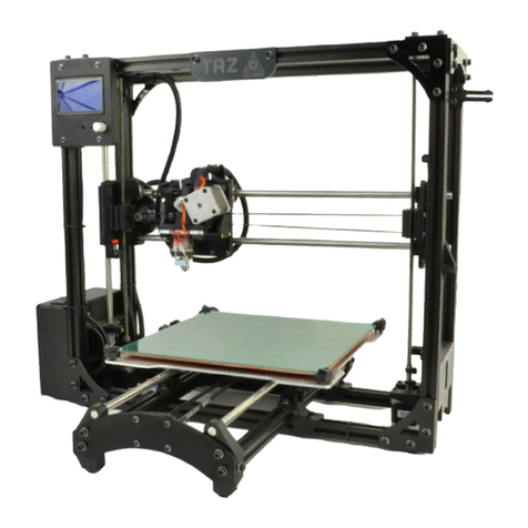
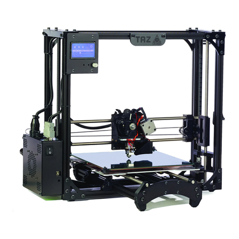
Place the TAZ frame and Y axis assembly on a fl at and
level surface. Remove the protective bubble wrap from
printing bed. Remove four pieces of tape from print bed.
2
Locate the four Y axis bolts (see green circles below).
Turning counter clockwise, remove each Y axis bolt
and set aside.
2
Quick Start Guide
setting up Your
TAZ 3D Printer
Buy printers, parts, and plastics at LulzBot.com
3
Locate the four Y axis mount brackets on the TAZ frame.
4
With the print surface facing up and the stepper motor
end of the Y axis facing back, slide the Y axis assembly in
between the Y axis mount brackets, aligning the holes on the
brackets with the bolt holes on the Y axis assembly.
Thread the four Y axis bolts through the brackets, into the
Y axis assembly.
Before completely tightening the Y axis bolts,
push down the Y axis aluminum bars against the
TAZ frame lower bars by slightly tilting the printer
on the side edge, enough to lift the feet of the Y
axis o of the table. The weight of the Y axis will
seat it against the TAZ frame. While the printer
is slightly tilted, tighten the four Y axis bolts.
Note:
5
Pull the print bed completely to the front of the printer
to access the Y axis connectors. You will fi nd matching
male and female 4-pin stepper motor connectors and 2-pin
end stop connectors. Connect the print surface connectors
and Y axis connectors by matching the male and female
connectors. The connector will click to ensure it is locked.
Locate one of the three small black zip ties that are included
in the documents bag. Wrap and tighten the zip tie around
the Y axis wiring and the black Y axis frame extrusion.
6
Locate the two connectors to the left of the print bed.
Connect the matching female and male large 2-pin heat
bed connectors and the small 2-pin connectors.
7
Locate the two small black zip ties that are included in
the documents bag. Wrap the two zip ties through the
slot, located on the left rear of the aluminum bed plate, and
around the print bed wires. Tighten the zip ties so the wire
cannot move freely. Cut o the excess end of the zip ties
with the needle-nose pliers included in the tool bag.
Make sure your printer work space is clear of any-
thing that could obstruct the movement of the
printer, and that there are no fl ammable fabrics
or liquids near the printer space. Avoid placing
your printer near a drafty window or air condi-
tioner vent.
Note:
8
Locate and remove, with the included 2.5mm hex
driver, the tool head 3mm screw in top center of
the X axis carriage. Remove the extruder head from the
Accessory Tray foam insert.
Place the extruder tool head mount onto the X axis carriage
bottom fi rst. The extruder mount will slide into the bottom
portion of the carriage and self center. Replace the
3mm screw to secure the extruder tool head onto the
X axis carriage.
Share ideas and collaborate at Forum.LulzBot.com
Connect the extruder assemblies' 4-pin connectors: match
the orange/red wire connector pair for the hot end and the
mixed color wired connector pair for the extruder motor.
Connect the matching pairs together so they lock and click.
Attaching Power Supply
9
Locate and unwrap the power supply, USB cables, and
AC power cable. Make sure the power supply is
completely unplugged before moving on to the next step.
10
Locate the power supply, USB connectors
and DC power receptacle on the back of the
electronics enclosure.
11
Connect the DC locking plug into the DC connector
on the TAZ electronics enclosure. The plug is keyed,
which may require rotating the plug until the keys line up
and the plug can be pushed in. Once the plug is pushed in,
turn the locking sleeve clockwise until it is tight against the
electronics enclosure.
12
Plug in the USB cable,
square B plug end,
into the USB receptacle on
the electronics enclosure.
Plug the A end of the USB
cable into your computer.
Attaching Filament Guide
13
Locate the filament guide with attached PTFE tube.
The filament guide easily attaches to the filament
guide mount on the top right side of the printer frame.
Before printing, familiarize yourself with
the TAZ cartesian type system
14
A The printer moves in three axes: X, Y, and Z. These
three axes allow the tool head to move to any point
within the print area. Note the location of the mechanical
end stops, which are small switches at the home point of
each axis. Each end stop switch allows the printer to find the
home, or starting point, of each axis.
BThe mechanical endstops should never be blocked during
the initial homing function or during a print.
Adjustment of the Z axis
15A Take the time to go through the leveling
procedure to help ensure that your prints are
consistent and trouble free. Connect to the printer as
described in the Printrun software section in the complete
TAZ 3D printer manual. Use the homing buttons to home the
X and Y axis.
Do not use the Home Z button until after the Z axis end stop
has been adjusted. Remove the red shipping clamps on the
Z axis smooth rods.
b Adjust the Z axis end stop trigger on the far left of the
printer, mounted on the X-axis motor mount. Once con-
nected to the printer in Pronterface, rotate the Z axis end
stop trigger clockwise to lower the bottom of the screw
approximately 1cm toward the Z axis end stop.
c Press the Home Z button to home the Z axis. The hot end
will lower to about a centimeter above the heated bed.
If there’s a grinding sound, stop, turn the printer o and
check that the Z axis is level in relation to the body of the
printer. Manually rotate one of the Z axis linear threaded rods
by hand if needed.
Raising the Z Axis
16A Use the +Z 10 button to move the Z axis up in
10mm increments. Raise the Z axis until the hot end
nozzle is approximately 40-50mm away from the print bed.
b With the Z axis above
the bed, use the included
150mm ruler to measure the
distance from the bottom
of the X axis smooth rod
and the top surface of the Y
axis aluminum bed plate on
the left side. The distance
measurement should be the
same on left and right.
If not, in Pronterface, turn
o the stepper motors by
pressing the Motors O
button. Turn the threaded rod on one side of the printer to
raise or lower that side to match the measurement on the
other side.
Fine Adjustment of the Z Axis End Stop
1 7
Rotate the screw counter-clockwise to raise the tip
of the screw by roughly the same amount as the
distance between the nozzle tip and the print surface. Press
the Home Z button to home the Z axis. The tip of the nozzle
should now be very close to the surface of the bed.
Leveling the Print Bed
1 8
A Slide a piece of paper underneath the nozzle and
adjust the Z axis end stop and home the Z axis until
the tip of the nozzle applies fi rm pressure on the paper.
You should be able to slowly pull out the sheet of paper with
only slight resistance.
B Move the hot end nozzle tip over to the far side of the
X axis by using the +X 100 button. As the X axis carriage
approaches the end of the X axis, use the +X 10 button and
the +X 1 button until the tip of the nozzle is near the front
right corner of the bed.
C Slide the same piece of paper under the nozzle and home
the Z axis. Adjust the corner's bed leveling screws so that
the tension felt when moving the paper under the nozzle
matches the tension felt previously. To raise or lower the
front right corner of the bed, adjust only the screw with
the spring. Turn the screw clockwise to lower the bed,
decreasing the tension felt when moving the paper. Turn the
screw counter-clockwise to increase the tension felt when
moving the piece of paper under the nozzle. Once adjusted,
press the +Z 10 button to raise the Z axis.
D Repeat the same process, fi rst raising the Z axis, then
using the +Y button to move the heated bed to place the
nozzle on the rear right corner of the bed. Adjust the height
of the bed using the same procedure as outlined above.
Finally, raise the Z axis and move the X axis carriage over to
the rear left corner of the bed and perform the same leveling
procedure to adjust the last corner.
NEXT UP: Create your fi rst 3D print.
Buy printers, parts, and plastics at LulzBot.com
Other manuals for TAZ

5

Other LulzBot 3D Printer manuals

LulzBot TAZ 5 User manual

LulzBot

LulzBot TAZ 5 User manual

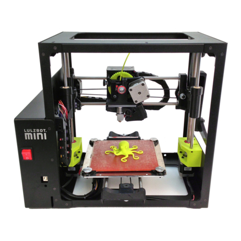
LulzBot Mini User manual

LulzBot

LulzBot Mini User manual

LulzBot TAZ Instruction Manual

LulzBot

LulzBot TAZ Instruction Manual

LulzBot TAZ 5 User manual

LulzBot

LulzBot TAZ 5 User manual

LulzBot TAZ User manual

LulzBot

LulzBot TAZ User manual

LulzBot Mini User manual

LulzBot

LulzBot Mini User manual

LulzBot TAZ Pro S Instruction Manual

LulzBot

LulzBot TAZ Pro S Instruction Manual

LulzBot TAZ 5 User manual

LulzBot

LulzBot TAZ 5 User manual

LulzBot Mini User manual

LulzBot

LulzBot Mini User manual

LulzBot Mini User manual

LulzBot

LulzBot Mini User manual

LulzBot TA Instruction Manual

LulzBot

LulzBot TA Instruction Manual

LulzBot TAZ User manual

LulzBot

LulzBot TAZ User manual

LulzBot TAZ User manual

LulzBot

LulzBot TAZ User manual

LulzBot TAZ 6 Instruction Manual

LulzBot

LulzBot TAZ 6 Instruction Manual

LulzBot TAZ SideKick User manual

LulzBot

LulzBot TAZ SideKick User manual

LulzBot TAZ 4 User manual

LulzBot

LulzBot TAZ 4 User manual

LulzBot TAZ 6 User manual

LulzBot

LulzBot TAZ 6 User manual

LulzBot Mini 2 User manual

LulzBot

LulzBot Mini 2 User manual

LulzBot TAZ 6 Instruction Manual

LulzBot

LulzBot TAZ 6 Instruction Manual

LulzBot TAZ 6 User manual

LulzBot

LulzBot TAZ 6 User manual

LulzBot TAZ User manual

LulzBot

LulzBot TAZ User manual

LulzBot TAZ 5 User manual

LulzBot

LulzBot TAZ 5 User manual

LulzBot TAZ Workhorse User manual

LulzBot

LulzBot TAZ Workhorse User manual

LulzBot TAZ 3.0 User manual

LulzBot

LulzBot TAZ 3.0 User manual

Popular 3D Printer manuals by other brands

AIO ZEUS quick start guide

AIO

AIO ZEUS quick start guide

Geeetech acrylic Prusa I3 Assemble manual

Geeetech

Geeetech acrylic Prusa I3 Assemble manual

Ultimaker PVA Removal Station Installation and user manual

Ultimaker

Ultimaker PVA Removal Station Installation and user manual

Stratasys P750K user guide

Stratasys

Stratasys P750K user guide

Dremel 3D40 Idea Builder Service instructions

Dremel

Dremel 3D40 Idea Builder Service instructions

Gembird 3DP-i3V2-01 Getting started guide

Gembird

Gembird 3DP-i3V2-01 Getting started guide

Stratasys Dimension 768/Elite Service manual

Stratasys

Stratasys Dimension 768/Elite Service manual

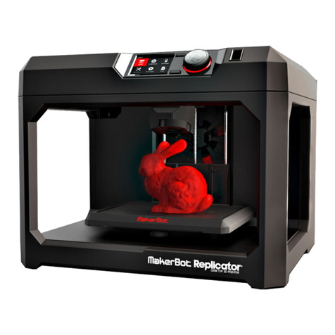
MakerBot Replicator quick start guide

MakerBot

MakerBot Replicator quick start guide

MYTRIX Dreamweaver user manual

MYTRIX

MYTRIX Dreamweaver user manual

Wasp 3MT HDP Original instructions

Wasp

Wasp 3MT HDP Original instructions

MiiCraft Hyper Series User manual for hardware

MiiCraft

MiiCraft Hyper Series User manual for hardware

Felix Storch Pro L quick start guide

Felix Storch

Felix Storch Pro L quick start guide

Bresser T-REX2 quick start guide

Bresser

Bresser T-REX2 quick start guide

Monoprice MP Maker Pro Mk.1 quick start guide

Monoprice

Monoprice MP Maker Pro Mk.1 quick start guide

Creality CR-10 Smart user manual

Creality

Creality CR-10 Smart user manual

RIGIDBOT 2117 instruction manual

RIGIDBOT

RIGIDBOT 2117 instruction manual

flsun SuperRacer user manual

flsun

flsun SuperRacer user manual

Creality 3dpRINTmILL user manual

Creality

Creality 3dpRINTmILL user manual

manuals.online logo
manuals.online logoBrands
  • About & Mission
  • Contact us
  • Privacy Policy
  • Terms and Conditions

Copyright 2025 Manuals.Online. All Rights Reserved.