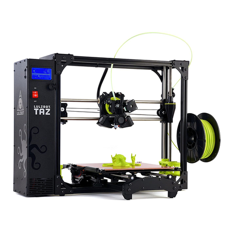
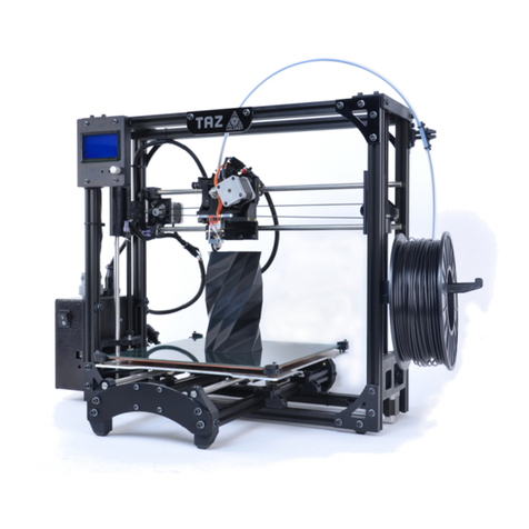
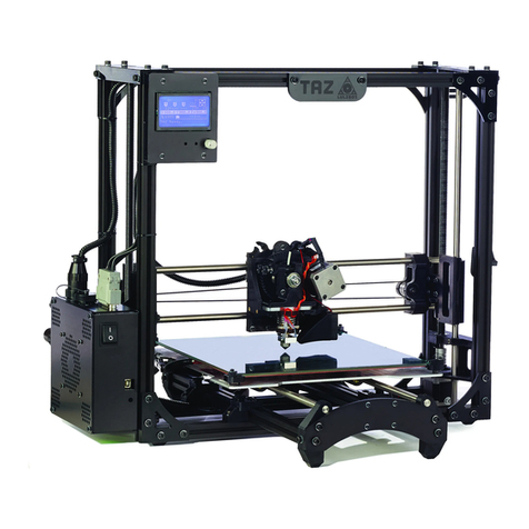
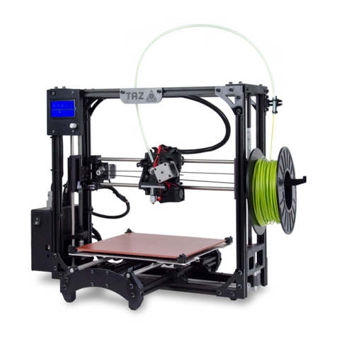
LulzBot TAZ 3.0 User manual

TAZ 3.0 User Manual
Aleph Objects, Inc.

LulzBotTM TAZ 3.0 User Manual
by Aleph Objects, Inc.
Copyright c
2013 Aleph Objects, Inc.
Permission is granted to copy, distribute and/or modify this document under the terms
of the Creative Commons Attribution-ShareAlike 3.0 Unported license (CC BY-SA 3.0).
Published by Aleph Objects, Inc., 626 W 66th Street, Loveland, Colorado, 80538 USA.
For more information, call +1-970-377-1111 or go to www.LulzBot.com and
www.AlephObjects.com.
ISBN: 978-0-9893784-3-7 20131211

Contents
WARNINGS
Safety Information ········· xi
Read Me First! ··························· xii
Hazards and Warnings ······················· xii
1Setup Your Printer ········· 15
1.1 Hardware Setup ························ 16
1.2 ABS & Acetone Solution Prep ················ 32
2Loading Filament ········· 33
33D Printer Software ········ 37
3.1 Software Overview ······················ 38
3.2 Installing Drivers ······················· 38
3.3 Printrun ···························· 38
3.4 Using Printrun ························ 41
3.5 CAD and 3D Modeling Software ··············· 45
4Your First 3D Print ········· 47
4.1 Bed Leveling ·························· 48
4.2 Set Temperature ······················· 52
4.3 Load Filament ························· 52
4.4 Home Printer ························· 53
4.5 Z Print Height ························· 54
4.6 Your First Octopus! ······················ 56
4.7 Remove Part ·························· 57
5Slic3r ············ 59
5.1 Introduction ·························· 60
5.2 Getting Slic3r ························· 61
5.3 First Print ··························· 62
iii

CONTENTS
5.4 Simple Mode ·························· 79
5.5 Expert Mode ························· 88
5.6 Configuration Organization ·················· 116
5.7 Repairing Models ······················· 118
5.8 Advanced Topics ······················· 119
5.9 Troubleshooting ························ 128
5.10 Slic3r Support ························· 129
6Printing with the Graphic LCD · · · · · · 131
6.1 GLCD Controller or Printrun Host? ············· 132
6.2 Multiple Connections ····················· 132
6.3 Putting Print Files On the SD Card ············· 133
6.4 Printing with the Graphic LCD ··············· 133
7Maintaining Your 3D Printer · · · · · · 139
7.1 Overview ···························· 140
7.2 Smooth Rods ························· 140
7.3 Threaded Rods ························ 140
7.4 PET Sheets ·························· 140
7.5 Hobbed Bolt ·························· 141
7.6 Software ···························· 141
7.7 Belts ······························ 141
7.8 Hot End ···························· 142
7.9 Electronics ··························· 142
8Advanced Usage ··········143
8.1 Intro ······························ 144
8.2 Changing nozzles ······················· 144
8.3 ABS/Acetone Glue ······················ 145
8.4 Using 1.75mm Filament ···················· 145
9Hardware and Software Source Code · · · · 149
10 3D Printer Support ·········151
10.1 LulzBot ···························· 152
10.2 Community ·························· 152
11 Contact Information ········153
11.1 Support ···························· 154
11.2 Sales ······························ 154
11.3 Websites ···························· 154
iv

CONTENTS
Index ·············155
Glossary ············159
v

List of Figures
1.1 Axes movement directions ···················· 16
1.2 Locate the four Y axis bolts ··················· 17
1.3 Remove the four Y axis bolts ·················· 17
1.4 Locate the four Y axis mounts on the frame ·········· 18
1.5 Screw in and tighten the four Y axis bolts ··········· 19
1.6 Connect the two connectors found at the rear of the Y axis · · 20
1.7
Wrap and tighten a zip tie around the Y axis wires to the Y axis
frame. ······························· 21
1.8 Connect the two connectors on the left of the print bed ···· 22
1.9 Locate the two zip ties found in the bag with the manual ··· 23
1.10
Tightly wrap the zip ties around the bed wires and through the
strain relief slot ·························· 23
1.11 Remove the tool head screw ··················· 24
1.12 Mount the extruder tool head ·················· 25
1.13 Connect the two tool head connectors ·············· 25
1.14 Power and USB receptacles ··················· 27
1.15 Power supply ··························· 27
1.16 24V DC Power supply plug and receptacle ··········· 28
1.17 The power supply plug correctly plugged in ··········· 28
1.18 Filament Guide ·························· 29
1.19 Filament Guide Mount ······················ 30
1.20 Filament Guide Setting ······················ 30
1.21 Axes movement directions ···················· 31
1.22 End stop locations ························ 31
2.1 Filament reel arm ························· 34
2.2 Filament run through the guide ················· 35
3.1 Printrun application for 3D printer control ··········· 39
3.2 Printrun ······························ 41
3.3 Printrun Functions ························ 42
3.4 Movement Controls ························ 43
4.1 Z end stop trigger ························· 48
4.2 Verifying the X and Y axis are square ·············· 50
vi

List of Figures
4.3 Extruder idler release ······················· 53
4.4 Extruder filament slot ······················ 54
4.5 Nozzle height ··························· 55
4.6 Z end stop trigger ························· 55
4.7 First layer adhesion ························ 56
5.1 Configuration Wizard: Welcome Screen ············· 64
5.2 Configuration Wizard: Firmware Type ············· 65
5.3 Configuration Wizard: Bed Size ················· 66
5.4 Configuration Wizard: Nozzle Diameter ············· 67
5.5 Configuration Wizard: Filament Diamter ············ 68
5.6 Configuration Wizard: Extrusion Temperature ········· 69
5.7 Configuration Wizard: Bed Temperature ············ 70
5.8 Configuration Wizard: End ··················· 71
5.9 Shapesmith online CAD tool. ·················· 75
5.10 Plater ······························· 76
5.11 Minimug model. ·························· 77
5.12 STL file loaded. ·························· 77
5.13 Preferences. ···························· 79
5.14 Simple Mode: Print Settings. ·················· 80
5.15 An example of insufficient top layers. ·············· 81
5.16 Creating a vase from a solid model. ··············· 82
5.17 An example of an object printed with support material. ···· 83
5.18 An example of brim. ······················· 84
5.19 Simple Mode: Filament Settings. ················ 85
5.20 Simple Mode: Printer Settings. ················· 86
5.21 Expert mode speed options. ··················· 89
5.22 Infill pattern settings. ······················· 91
5.23 Infill pattern: Line (344.51mm / 5m:20s) ············ 91
5.24 Infill pattern: Rectilinear (350.57mm / 5m:23s) ········ 91
5.25 Infill pattern: Concentric (351.80mm / 5m:30s) ········· 92
5.26 Infill pattern: Honeycomb (362.73mm / 5m:39s) ········ 92
5.27 Infill pattern: Hilbert Curve (332.82mm / 5m:28s) ······· 92
5.28 Infill pattern: Archimedean Chords (333.66mm / 5m:27s) ··· 92
5.29 Infill pattern: Octagram Spiral (318.63mm / 5m:15s) ····· 93
5.30
Infill pattern comparison in a complex object. Left to Right:
honeycomb, line ·························· 93
vii

List of Figures
5.31
Infill patterns at varying densities. Left to Right:
20%,40%,60%,80%. Top to Bottom: Honeycomb, Concentric,
Line, Rectilinear, Hilbert Curve, Archimedean Chords,
Octagram Spiral ·························· 94
5.32 Infill advanced settings. ······················ 95
5.33 Retraction settings. ························ 96
5.34 Skirt settings. ··························· 98
5.35 Cooling strategy. ························· 99
5.36 Cooling advanced settings. ···················· 101
5.37 Support structure options. ···················· 102
5.38 Minimug model, tilted 45◦.···················· 103
5.39 Support infill pattern: Rectilinear ················ 104
5.40 Support infill pattern: Rectilinear Grid ············· 104
5.41 Support infill pattern: Honeycomb ················ 104
5.42 Example of pattern angle rotated 45◦.·············· 105
5.43
Multiple extruder options - Printer Settings Tab (General). Note
the two extruders defined in the left-hand pane. ········ 106
5.44 Multiple extruder options - Printer Settings Tab (Extruder). ·106
5.45 Plater with multiple filament options. ·············· 107
5.46 Multiple extruder options - Print Settings Tab. ········· 108
5.47 Multiple extruder options - Tool change G-code. ········ 108
5.48 Extrusion widths options. ···················· 110
5.49 Example model highlighting use case for variable layer heights. 111
5.50 Example with normal layer height. ··············· 112
5.51 Variable layer height options - Info. ··············· 113
5.52 Variable layer height options - Layers. ·············· 114
5.53 Example with variable layer height. ··············· 114
5.54 Example print with variable layer height. ············ 115
5.55 Example with skipped layers. ·················· 115
5.56 Saving a profile. ·························· 117
5.57 Deleting a profile. ························· 117
5.58 FreeCAD part repair. ······················· 118
5.59 Sequential printing options. ··················· 119
5.60 The clearance cylinder around an extruder. ··········· 120
5.61 Post-processing script option. ·················· 126
5.62
Example post-processing script to display Slic3r environment
variables. ····························· 126
5.63 Example post-processing script to print each line to output. · · 127
viii
List of Figures
6.1 GLCD Info Screen ························ 133
6.2 Main menu ···························· 135
6.3 Configuration Menu ························ 137
6.4 Configuration Menu ························ 138
ix


WARNINGS
Safety Information

WARNING!
Read Me First!
READ THIS MANUAL COMPLETELY BEFORE UNPACKING AND
POWERING UP YOUR PRINTER.
Hazards and Warnings
The TAZ 3D printer has motorized and heated parts. When the printer is
in operation always be aware of possible hazards.
Electric Shock Hazard
Never open the electronics case when the printer is powered on. Before
removing the electronics case cover always power down the printer and
completely turn off and unplug the power supply and allow the power
supply to discharge for at least 1 minute.
Burn Hazard
Never touch the extruder nozzle or heater block without first turning off
the hot end and allowing it to completely cool down. The hot end can take
up to twenty minutes to completely cool. Never touch recently extruded
plastic. The plastic can stick to your skin and cause burns. The heated bed
can reach high temperatures capable of causing burns.
Fire Hazard
Never place flammable materials or liquids on or near the printer when
powered or in operation. Liquid acetone and vapors are extremely flammable.
Pinch Hazard
When the printer is in operation take care to never put your fingers in the
moving parts including the belts, pulleys, or gears. Tie back long hair or
clothing that can get caught in the moving parts of the printer.
xii

HAZARDS AND WARNINGS
Static Charge
Make sure to ground yourself before touching the printer, especially the
electronics. Electrostatic discharge can damage electronic components.
Ground yourself by touching a grounded source.
Age Warning
For users under the age of 18, adult supervision is recommended. Beware
of choking hazards around small children.
xiii


Setup Your Printer

Setup Your Printer
1.1 Hardware Setup
1.
Your printer has been calibrated and tested, however, after unpacking
all of the components you will need to re-mount the Y axis onto the
frame and connect the bed and Y axis connectors. You will also
need to re-mount the extruder tool head. Please follow the steps
completely to make certain that the extruder tool head and Y axis
are re-mounted correctly. You will then be on your way to your first
print. Use Fig. 1.1 to see which direction the three axes move, as the
following instructions will reference the X, Y, and Z axes.
Figure 1.1: Axes movement directions
2.
Place the TAZ frame and Y axis assembly on a flat and level surface.
Move to the Y axis assembly and find the four Y axis bolts. The four
bolts located on the Y axis aluminum frame bars, have large plastic
knobs that allow the bolts to be easily turned by hand (Fig. 1.2, page
17). Turning counter clock-wise, remove each of the four Y axis bolts
and set aside (Fig. 1.3, page 17).
16

1.1. HARDWARE SETUP
Figure 1.2: Locate the four Y axis bolts
Figure 1.3: Remove the four Y axis bolts
17

Setup Your Printer
3.
On the TAZ frame locate the four Y axis mount brackets shown in Fig.
1.4 (pg. 18). With the print surface facing up and the stepper motor
end of the Y axis facing back, slide the Y axis assembly in between
the Y axis mount brackets. The four Y axis mount brackets will line
up with the Y axis bolt holes on the Y axis assembly. Thread the four
Y axis bolts through the brackets, into the Y axis assembly (Fig. 1.5,
page 19). Before completely tightening the Y axis bolts make sure the
Y axis aluminum bars are pushed down against the TAZ frame lower
bars. While pushing on the black Y axis square extrusions tighten
the four Y axis bolts. The printer can now be set flat on the table.
Figure 1.4: Locate the four Y axis mounts on the frame
18

1.1. HARDWARE SETUP
Figure 1.5: Screw in and tighten the four Y axis bolts
4.
The next step of installing the Y axis is connecting the print surface
connectors and Y axis connectors. Pull the print bed completely to
the front of the printer to get access to the Y axis connectors. You
will find matching male and female 4 pin stepper motor connectors
and two pin end stop connectors. Connect the matching male and
female connectors (Fig. 1.6, page 20); make sure the connector’s lock
clicks to be sure that it is secured.
19

Setup Your Printer
Figure 1.6: Connect the two connectors found at the rear of the Y axis
5.
Locate one of the three small black zip ties that are included in the
documents bag. Wrap and tighten the zip tie around the Y axis wiring
and the black Y axis frame extrusion as shown in figure 1.7 (page 21).
20
Table of contents
Other LulzBot 3D Printer manuals

LulzBot
LulzBot TAZ 6 User manual

LulzBot
LulzBot TAZ 5 User manual

LulzBot
LulzBot TAZ Instruction Manual

LulzBot
LulzBot TAZ Pro S Instruction Manual

LulzBot
LulzBot TAZ User manual

LulzBot
LulzBot TAZ User manual

LulzBot
LulzBot TAZ User manual

LulzBot
LulzBot Mini User manual
LulzBot
LulzBot TA Instruction Manual

LulzBot
LulzBot TAZ User manual

LulzBot
LulzBot Mini 2 User manual

LulzBot
LulzBot TAZ Workhorse User manual

LulzBot
LulzBot TAZ 5 User manual

LulzBot
LulzBot TAZ 4 User manual

LulzBot
LulzBot TAZ SideKick User manual

LulzBot
LulzBot TAZ 6 User manual

LulzBot
LulzBot Mini User manual

LulzBot
LulzBot Mini User manual

LulzBot
LulzBot TAZ 5 User manual

LulzBot
LulzBot TAZ User manual