Lumel ULT20 User manual

ULTRASONIC LEVEL TRANSDUCER
ULT20
USER’S MANUAL

ULT20 - User’s manual_rev.A 2
Contents
1 Application.......................................................................................................................................3
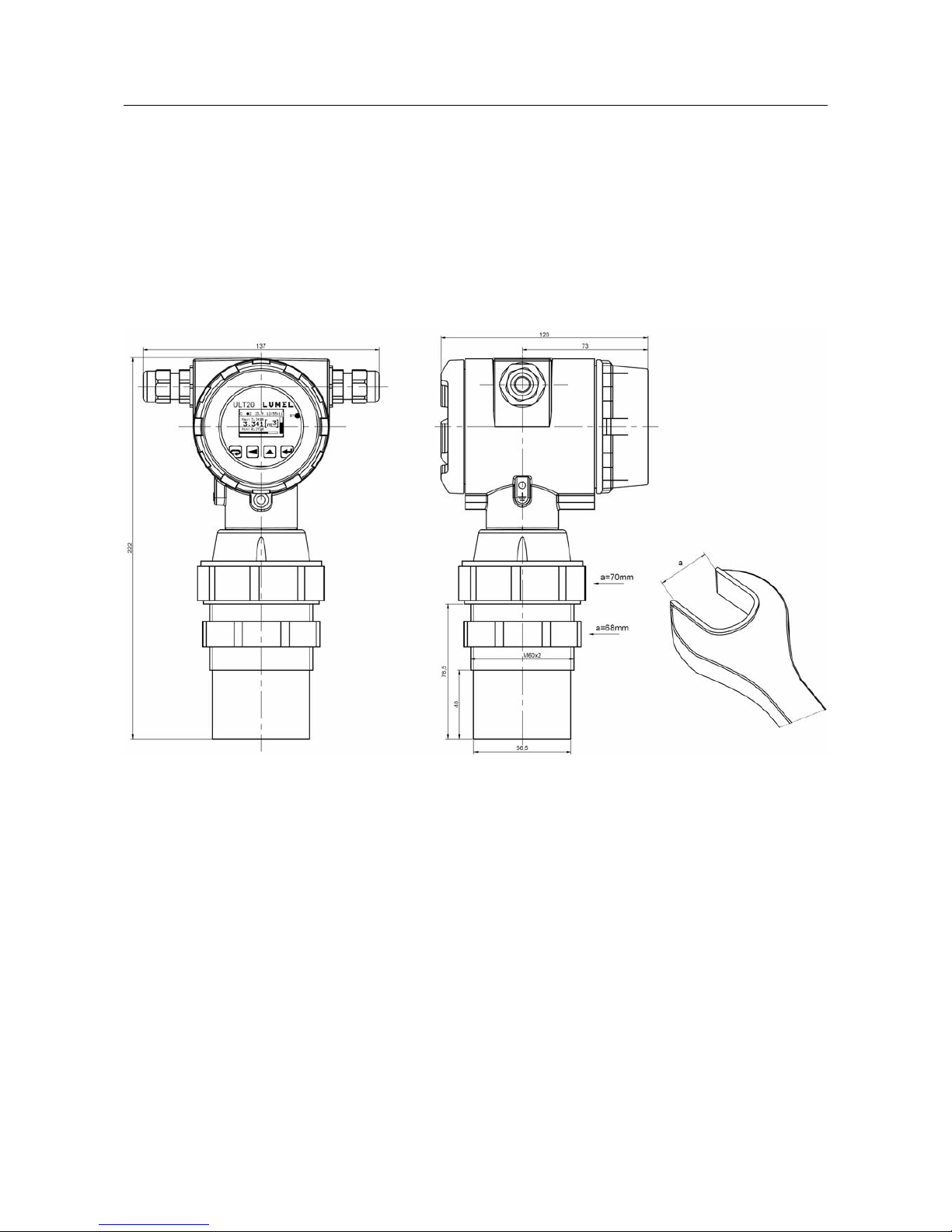
2 Transducer set...................................................................................................................................4
3 Basic requirements, operational safety ............................................................................................5
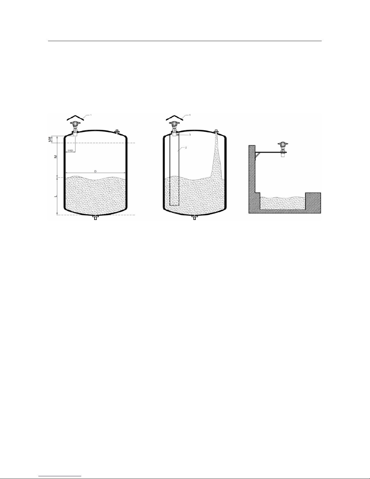
4 Installation .......................................................................................................................................6
4.1 Method of installation ..............................................................................................................6
4.2 External connections diagram ..................................................................................................7
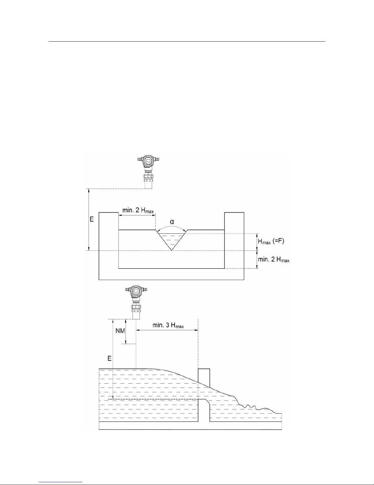
4.3 Examples of applications..........................................................................................................9
5 Operation .......................................................................................................................................11
5.1 Description of front panel ......................................................................................................11
5.2 Functions of buttons ...............................................................................................................12
5.3 Transducer parameters programming ....................................................................................14
5.3.1 Changing value of selected parameter ...........................................................................16
5.3.2 Programmable transducer parameters ............................................................................17
5.4 Functions of the transducer ....................................................................................................23
5.4.1 Distance measurement ...................................................................................................23
5.4.1.1 Measured value averaging ......................................................................................24
5.4.1.2 Minimum and maximum measured values ............................................................24
5.4.1.3 Individual characteristics ........................................................................................25
5.4.1.4 Counter....................................................................................................................26
5.4.2 Analog output .................................................................................................................26
5.4.3 Binarny pulse output ......................................................................................................27
5.4.4 Alarm outputs .................................................................................................................28
5.4.5 LCD display ..................................................................................................................29
5.5 Factory settings.......................................................................................................................31
5.6 Archiving ...............................................................................................................................33
5.6.1 Structure of record .........................................................................................................34
5.6.2 Measured values archiving .............................................................................................35
5.6.3 Events archiving .............................................................................................................36
5.6.4 Downloading archived data ............................................................................................38
5.7 RS-485 interface ....................................................................................................................39
5.7.1 Connection .....................................................................................................................40
5.7.2 Description of MODBUS protocol implementation. .....................................................41
5.7.3 Implemented functions of MODBUS protocol ..............................................................41
5.7.4 Map of registers .............................................................................................................41
5.7.4.1 Registers 4000 – 4081.............................................................................................42
5.7.4.2 Registers 4300 – 4435............................................................................................48
5.7.4.3 Registers 5000 – 5272............................................................................................53
5.7.4.4 Registers 7500 – 7533 and 8000 – 8065 ................................................................53
5.7.4.5 Registers 7800 – 7949 and 8200 – 8498.................................................................55
5.8 USB interface .........................................................................................................................59
6 Error codes .....................................................................................................................................60
7 Technical data ................................................................................................................................61
8 Ordering code ................................................................................................................................63

ULT20 - User’s manual_rev.A 3
1 Application
Ultrasonic level transducer ULT20 are designed to measure distance, and after
programming functions which process the measured value of distance they can be used to
measure the filling of tanks, silos, to count the flow and level measurement in open
channels and wherever there is a need to measure the distance as a basic measured
value. Additional interfaces and additional equipment in the form of programmable alarms
allow for the measured data transmission and recording and local control based on event
system. Built-in LCD display, which, together with the keyboard creates a local user
interface allows for any change of operating parameters and viewing the current status of
the device, including the reading of measured values.
Built-in memory of events and archived data storage allow for archiving of status of
ULT20 transducer operation. Archived data is available through the interfaces: RS485 and
USB. At the same time, these interfaces can also be used for programming and
monitoring of ULT20 transducer operation.
ULT20 transducers have a robust housing made of aluminum, which protects the
transducer from external influences. View of ULT20 transducer is shown in Fig.1
ULT20 transducers are characterized by:
•The measurement distance in the range of 0,5 ... 8 m with automatic temperature
compensation (temperature sensor integrated in the measuring head).
•Analog output in 0/4 ... 20 mA standard with configurable output characteristics and
configurable output control value with manual output control included.
•Two-wire RS485 interface in MODBUS standard.
Fig. 1: View of ULT20 transducer.

ULT20 - User’s manual_rev.A 4
•Two programmable alarms with NO contact. Each alarm can be configured to work
in the selected mode and to response to any value measured together with the cur-
rent time. In addition, a change in the position of the relay contact may be delayed
by a programmed time. User can also activate the memory function of alarm activa-
tion.
•Galvanically separated counter binary output with programmable pulse weight.
•Built-in graphic LCD display and buttons for programming all functions of the trans-
ducer. In addition, using the display, the User can view all the measured values.
•Password protection of the transducer (settings) menu.
•Built-in galvanically isolated USB interface for configuration, viewing the status of
the transducer and reading the archives.
•Built-in real time clock with automatic adjustment for Daylight Saving Time. In the
absence of power supply the clock is supplied by an internal lithium battery.
•Built-in event memory allows for the registration of system events such as power fa-
ilure, alarms activation or deactivation, etc.
•Built-in memory of archive data with a choice of recording in five independently con-
figurable channels with any choice of the archived value and the value triggering ar-
chiving.
•Two 32-point individual characteristics allow the User to scale the measured value
according to two different values, for example: the level and the flow.
•Registration of minimum and maximum values for all measured and calculated pa-
rameters with the date and time of occurrence.
•The possibility of averaging the measured value by moving average.
•The possibility of Individual assignment of units to the value calculated according to
the desired individual characteristic.
•Built-in diagnostics function for continuous monitoring the operating status of the
device.
•Aluminum housing with IP65 protection degree.
•Low supply voltage (operation from 12 V) and a wide range of supply voltage (12 ...
40 V) allowing for operation in a system powered with batteries.
2 Transducer set
The set of ULT20 transducer contains:
•ULT20 transducer 1 pc
•User’s manual 1 pc
•Warranty Card 1 pc

ULT20 - User’s manual_rev.A 5
3 Basic requirements, operational safety
ULT20 transducer, with respect to user’s safety, complies with the requirements of EN
61010-1 standard.
Safety instructions
•The assembly and the installation of the electrical connections should be carried out
by a duly qualified electrician.
•Before turning on the transducer verify the connections.
•The device is intended for installation and use in industrial electromagnetic environ-
ments.
•A switch or a circuit-breaker should be installed in the building or facility located
near the device, easily accessible to the operator, and suitably marked.
•Disassembly of the transducer electronic system during the warranty period voids
the warranty.

ULT20 - User’s manual_rev.A 6
4 Installation
ULT20 transducers can be installed in any position. During installation it is recommended
to avoid mounting with the sensor facing up, as it can cause severe deposition of contami-
nants on the sensor membrane and lead to measurement errors. During installation the
sensor should be positioned in such a way that the measuring head is perpendicular to
the surface, to which the distance is to be measured. The view and dimensions of ULT20
transducer are shown in Fig .2.
4.1 Method of installation
ULT20 transducers are designed for installation in a hole with a diameter of 60 to 65 mm.
The maximum thickness of the material wherein the hole is formed is 20 mm.
On the outside of the sensor there is a M60x2 thread, which allows direct attachment of
the sensor to the mounting bracket or to the flange mounted in the tank. Take special
precautions to make sure that the sensor is not damaged during direct assembly in the
threaded hole. Never screw or turn off the transducer by twisting the aluminum housing
part .
Cable grommets located on the side of the housing are used for conductors connection.
While connecting conductors, special care should be taken that no cable touches the con-
1. Fig. 2. View and dimensions of the transducer.

ULT20 - User’s manual_rev.A 7
ductive part of the housing, or other cables. After completion of conductors connection the
cable grommets should be tightened.
All circuits are galvanically isolated from other circuits. The exception is the power supply
and interface for connecting the measuring head, which is not galvanically isolated from
the power supply of the transducer. This is due to the fact that in some cases the terminal
of the negative supply potential must be grounded in order to provide a stable indications.
Other circuits, such as analog output, RS-485 interface, USB interface and alarm outputs
are separated from each other and from power supply as shown in Fig. 3.
4.2 External connections diagram
ULT20 transducer is equipped with screw jacks for connecting conductors up to 1 mm2and
2 mm2for alarm signals terminal block. All external signals are routed to three slots. The
first slot JE2 is used to connect signals: analog output and power supply. The second slot
JE1 is used to connect signals: binary output and RS485 interface. The third slot includes
terminals of alarm relay contacts. Access to the terminals is possible after removing the
rear cover of the transducer. The terminal for USB port is located on the front panel of the
transducer. The location of connectors and terminals description is shown in Fig. 4.
Fig. 3. Galvanic isolation in ULT20 transducer.

ULT20 - User’s manual_rev.A 8
Signal Description
An.Out+, An.O-
ut- Analog current output: 0/4..20 mA.
SUPPLY+,
SUPPLY- Transducer supply terminal 12..40 V d.c.
RS485_A,
RS485_B,
GNDI
Interface signal RS485
BIN OUT+,
BIN OUT-
Binary pulse output. Transistor output NPN, where BIN OUT+ is transistor collector, and BIN
OUT- to transistor emitter.
ALARM 1 Output of alarm 1 – semiconductor relay.
ALARM 2 Output of alarm 2 – semiconductor relay.
Note: The outside of the housing is equipped with a terminal to which the PE cable is to be
connected. All shieldings of the signal cables should also be connected to this terminal.
When shielded cables are used, be sure to connect each cable shield at only one point.
Fig. 4. Location of signal connectors.

ULT20 - User’s manual_rev.A 9
4.3 Examples of applications
The following figure shows the examples of installation and usage of the ULT20 transducer
in the application of a tank filling measurement and in the application of open channel level
or flow measurement. Additionally, Fig. 6 presents an example of flow measurement in a
channel using a venturi (bends) with a triangular cut-out. However, the flow measurement
requires the use of appropriate tubes or separators.
Fig. 5: Examples of installation.
Markings in Figure 5:
•NM – dead zone distance – zone in which there is no measurement or the distance
value at which the tank is fully filled.
•M – distance between the measured medium and the measuring head.
•L – height (level) of the tank filling.
•D – tank diameter.
•1 – weather cover mounted above the ULT20 transducer.
•2 – inner cover when measuring medium with strong wave motion, e.g. during rapid
filling of the tank or when measuring the level in a tank with a stirrer.
•3 – ventilation hole in the inner cover.
The ULT20 transducer continuously measures M distance. To determine the actual
percentage of filling of the tank, program the transducer properly and set the points in the
parameters of individual characteristics as follows:
•X1 – measured value for which we want to obtain level 0. Enter L+M as the value.
•Y1 – expected value for X1 – enter value 0.

ULT20 - User’s manual_rev.A 10
•X2 – value for which we want to obtain level 100 %. Enter NM as the value.
Also Mvalue may be entered with proper filling (Y2) assigned to it.
•Y2 – value to be indicated for X2 value. It will be the value of 100 % for X2
determined by NM or proper filling value if X2 has been defined by M value.
The 1/6D transducer mounting distance shown in the figure indicates the recommended
mounting method for the transducer on the tank. It is not advisable to mount the
transducer in the tank axis.
When measuring the flow in open channels, venturi (baffles) with a triangular cut-out are
often used. An example of such an application is shown in Figure 6.
Fig. 6: Example of flow measurement in an open channel.

ULT20 - User’s manual_rev.A 11
Markings in the drawing:
•E - measured value when there is no flow (minimum distance from the sensor for
which the tide is zero).
•F - distance for nominal flow.
For specific values E and F and on the basis of the characteristics of the venturi used, it is
possible to introduce an individual characteristic that converts the indication into a flow va-
lue.
5 Operation
ULT20 transducer is equipped with buttons and an LCD display, which for ease of use are
placed on the front panel. After powering on the LCD displays Welcome Screen with dia-
gnostic messages, software version and serial number. In the case of irregularities or da-
mage to any of the components the boot process is stopped, and the display shows an er-
ror message. In this case, the User may need to press the accept button.
5.1 Description of front panel
View of the front panel ULT20 transducer, after removing the protective ring, is shown in
Fig. 7. LCD display and four buttons, which together make the User interface, are placed
on the front panel. Additionally, the panel is equipped with USB port for connecting the
transducer to a computer for configuration, reading the archives, or preview of currently
measured and calculated values.

ULT20 - User’s manual_rev.A 12
RT diode, which is placed on the front panel, changes its state after each update of values
read from the measuring head module.
5.2 Functions of buttons
Cancel button:
•Leaving the menu and exit to the main screen.
•Leaving the lower level of the menu and return to the higher level.
•No change to the set value (when editing a parameter value)
Button to change digits:
•Changing the displayed value - switching between main screens.
•Navigating the menu - decrease the position of the menu.
•Reducing the adjusted valued during parameter editing and selection of ad-
justable variable from the list of settings, e.g. the type of alarm.
•Change of adjustable digit while setting numerical parameters.
Fig. 7: Front panel.

ULT20 - User’s manual_rev.A 13
Value increase button:
•Changing the displayed value - switching between main screens.
•Navigating the menu - increase the position of the menu.
•Increase the value of a selected parameter or increase the of a digit during
the change of numerical value.
Enter button:
•Entering the programming mode (hold this button for minimum 3 seconds)
•Navigating the menu – entering the parameter value edit mode or entering
the selected lower level menu.
•Accepting the changed parameter value
Deleting the memory of alarm no. 1 (hold down the buttons for minimum 3
seconds).
Deleting the memory of alarm no. 2 (hold down the buttons for minimum 3
seconds).
Deleting the minimum, maximum value of the transducer (hold down the buttons for
minimum3 seconds). Value or values which will be deleted depend on the displayed
parameter (the current main screen), e.g. the counter is reset only when the User
pushes a combination of buttons on the screen where the counter values are di-
splayed. If the transducer menu is password-protected, then before using a combi-
nation of buttons, the User will be prompted for a password.
All events related to deleting saved minimum, maximum value, memory of alarm activation
and the counter status are indicated by ULT20 transducer by displaying an appropriate
message, example is given in Fig. 8.

ULT20 - User’s manual_rev.A 14
5.3 Transducer parameters programming
Programming the transducer parameters is possible via RS485 interface, USB interface
and through direct programming with buttons and LCD display.
The direct programming process is facilitated by the transducer menu which contains the
settings grouped in groups containing all the parameters related to the given functionality
of the transducer, e.g. all parameters of serial interface are grouped in RS-485.menu.
Switching to the transducer menu is done by pressing the Enter button for at least 3 se-
conds . In case the parameters change is password protected, the User will be
prompted for a password before entering the menu. Entering a wrong password allows the
User to enter the menu but the change of parameters is locked - the mode of parameters
browsing. Entering the correct password will move the User to the programming matrix.
Navigating around the programming matrix is done by using . After selecting a gro-
up of parameters whose configuration is to be changed, press the Enter button to move to
the parameters of the group. The selection of the parameter whose value is to be modified
is done in the same way as the group selection. In case of the resignation of the parameter
change, the User can leave the parameter or a group of parameters change mode by
pressing the Cancel button . If during programming no button is pressed for the time of
30 seconds, the transducer automatically leaves the programming mode and returns to the
last screen. The programming matrix is shown below.
ME-
ASU-
RE
AvgTime
Time of
measure-
ment
avera-
ging.
The
length of
moving
window
Pulse K
Defines
the
value of
the trans-
ducer
change
to which
the bina-
ry output
pulse
should
corre-
spond.
PAR1 Unit
Unit for
value no.
1.
Over Lo
Minimum
value.
Below
this. Va-
lue lower
overrun
Over Hi
Maxi-
mum va-
lue. Abo-
ve this
value Up-
per over-
run
Deci-
malP
decimal
point po-
sition.
Resolu-
tion
Ind.Char
Enable or
disable
individual
charateri-
stic
Point No
number
of points
of
individual
character
istic
X1
Measu-
red value
-point 1.
Y1
Expected
value for
value
X1.
X2
Measure
d value -
point 2
Y2
Expected
value for
value X2.
X3
Measure
d value
-point 3.
Y3
Expected
value for
value
X3.
... ... X32
Measure
d value
-point
32.
Y32
Expected
value for
value
X32.

ULT20 - User’s manual_rev.A 15
PAR2 Unit
Unit for
value
no . 1
Over Lo
Minimum
value.
Below
this va-
lue
lower
overrun
Over Hi
Maximum
value.
Above
this value
upper
overrun
Deci-
malP
position
of
decimal
point.
Resolu-
tion
Ind.Char
Enable or
disable
individual
character
istic
Point No
number
of points
of
individual
character
istic
X1
Measure
d value
-point 1.
Y1
Expected
value for
value X1.
X2
Measure
d value
-point 2
Y2
Expected
value for
value X2.
X3
Measure
d value
-point 3.
Y3
Expected
value for
value X3.
... ... X32
Measure
d value
-point
32.
Y32
Expected
value for
value
X32.
ALAR
M 1 Pa-
ram.Al
Alarm
control
value
Type Al
Type of
alarm.
OverLo
Al
Lower
threshold
of alarm
state
change.
OverHi
Al
Upper
threshold
of alarm
state
change
DlyOn.Al
Delay of
alarm
activation
DlyOff.Al
Delay of
alarm
deactivati
on
Sg.Ke-
ep.Al
Alarm
activity
memory
ALAR
M 2 Pa-
ram.Al
Alarm
control
value
Type Al
Type of
alarm.
OverLo
Al
Lower
threshold
of alarm
state
change.
OverHi
Al
Upper
threshold
of alarm
state
change
DlyOn.Al
Delay of
alarm
activation
DlyOff.Al
Delay of
alarm
deactivati
on
Sg.Ke-
ep.Al
Alarm
activity
memory
An.O-
UT Pa-
ram.An
Control
value of
analog
output
Type An
Type of
analog
output.
AnIn Lo
Control
Value
specify-
ing mini-
mum va-
lue at
analog
output
AnIn Hi
Control
Value
specify-
ing maxi-
mum va-
lue at
analog
output
AnMa-
nVal
Value of
analog
output
current
for manu-
al opera-
tion.
RS-485 Address
Address
of the
transdu-
cer on
the ne-
twork
ModeU-
nit
Type of
transmiss
ion frame
BaudRa-
te
Baud
rate
of trans-
mission
SYS-
TEM Time
Current
time acc.
to
internal
clock.
Date
Current
date acc.
to
internal
clock.
AutoTi-
me
Automati
c day
saving
time.
LcdBri-
ght
Brightnes
s of LCD
backlight
.
Lcd-
Contr.
Contrast
of
display.
LcdStyle
Style of
display.
Langu-
age
Languag
e of
menu
and
message
s
V1minRs
t
Delete
minimum
acc. to
PAR1
V1ma-
xRst
Delete
maxi-
mum
acc. to
PAR1
V2minRs
t
Delete
minimum
acc. to
PAR2.
V2ma-
xRst
Delete
maximu
m acc. to
PAR2.
TminRe-
set
Delete
minimum
value of
temperat
ure
TmaxRe-
set
Delete
maximu
m value
of
temperat
ure.
CntRe-
set
Delete
(reset)
value of
counter.
Pas-
sword
Passwor
d to
paramete
rs value
change
Def.Par
Restore
factory
settings.
EventDel
Delete
event
archive.
DataDel
Delete
data
archive.
Firm.Ver
transdu-
cer so-
ftware
version.
SerialNo
transduc
er serial
number.

ULT20 - User’s manual_rev.A 16
ARCH.
1ArchVal
Variable
whose
value is
to be
recorded
TrigVal
Variable
whose
value
triggers
recording
process.
ArchTy-
pe
Type of
archiving
-
triggering
Period
Frequenc
y of data
recording
DlyOn.A
r
Delay of
recording
activation
.
DlyOff.A
r
Delay of
recording
deactivati
on.
Trig.Lo
Low
value to
change
the state
of
recording
triggering
.
Trig.Hi
Upper
value to
change
the state
of
recording
triggering
.
ARCH.
2ArchVal
as for
ARCH.1
TrigVal
as for
ARCH.1
ArchTy-
pe
as for
ARCH.1
Period
as for
ARCH.1
DlyOn.A
r
as for
ARCH.1
DlyOff.A
r
as for
ARCH.1
Trig.Lo
as for
ARCH.1
Trig.Hi
as for
ARCH.1
ARCH.
3ArchVal
as for
ARCH.1
TrigVal
as for
ARCH.1
ArchTy-
pe
as for
ARCH.1
Period
as for
ARCH.1
DlyOn.A
r
as for
ARCH.1
DlyOff.A
r
as for
ARCH.1
Trig.Lo
as for
ARCH.1
Trig.Hi
as for
ARCH.1
ARCH.
4ArchVal
as for
ARCH.1
TrigVal
as for
ARCH.1
ArchTy-
pe
as for
ARCH.1
Period
as for
ARCH.1
DlyOn.A
r
as for
ARCH.1
DlyOff.A
r
as for
ARCH.1
Trig.Lo
as for
ARCH.1
Trig.Hi
as for
ARCH.1
ARCH.
5ArchVal
as for
ARCH.1
TrigVal
as for
ARCH.1
ArchTy-
pe
as for
ARCH.1
Period
as for
ARCH.1
DlyOn.A
r
as for
ARCH.1
DlyOff.A
r
as for
ARCH.1
Trig.Lo
as for
ARCH.1
Trig.Hi
as for
ARCH.1
5.3.1 Changing value of selected parameter
To increase the value of the selected parameter, press button . Pressing the button in-
creases the currently set digit by 1, but after 9, is reached, pressing the button sets the va-
lue to 0. After setting the desired digit value, the User should go to the next digit by pres-
sing the button . After setting the desired parameter press Enter button to leave the
parameter change menu and return to the previous parameter. Changing the sign of the in-
put value is possible when setting the last digit (most significant).
Changing floating point values is done in two steps. The first step is to set digits and the
sign in accordance with the above-described algorithm. The second step, which starts
after Enter button is pressed, is setting the decimal point position. After setting the decimal
point to the desired position, press the Enter button.
When an incorrect parameter value is entered, the new value is not accepted and the pa-
rameter automatically returns to the previous value.
Change of parameters other than numerical ones is done by selecting desired setting from
the parameters list using buttons . After selecting the desired settings, press Enter
button to load the setting or Cancel button to return to the previous value and to le-
ave the parameter change mode.
Fig. 9. Programming matrix.

ULT20 - User’s manual_rev.A 17
5.3.2 Programmable transducer parameters
ULT20 transducers have a number of programmable parameters which are listed in the
tables below.
Table 1
Measure
Symbol of
parameter Description Scope of changes
AvgTime
Measurement time expressed in seconds
– this is the averaging time of the
measurement result understood as the
length of the moving window
0...3600 seconds. Entering value of 0 will refresh
the measurement result with maximum speed of
up to about 10 measurements per second.
Pulse K
Weight of pulse of binary output –
determines the change of counter which
will generate 1 pulse at binary output.
0...999999
Table 2
PAR1 andPAR2
Symbol of
parameter Description Scope of changes
Unit Unit displayed next to the measured value
none
m
l
m3
T
%
l/s
l/min
l/h
kg/h
m3/h
T/h
Over Lo Lower overrun – measured value below
which lower overrun is reported. -99999...999999
Over Hi Upper overrun – measured value above
which upper overrun is reported. -99999...999999
DecimalP Decimal point - displaying precision.
Determines the number of decimal places.
Value Description
000000 No decimal places
0000.0 One decimal place
000.00 Two decimal places
00.000 Three decimal places

ULT20 - User’s manual_rev.A 18
0.0000 Four decimal places
AUTO
Automatic format. Resolution is
adjusted to the displayed value in a
way ensuring the best possible
precision.
Ind.Char
Individual characteristic – enable or
disable the recalculation of the measured
value by the entered individual
characteristic.
Value Description
Disabled Individual characteristic disabled
Enabled Individual characteristic enabled
Point No Number of points of Individual
characteristic 2...32
Xn* Point of individual characteristic –
measured value -99999...999999
Yn* Point of individual characteristic –
expected value for Xn measured valued. -99999...999999
*n – point numberofindividual characteristic from 1 to 32. The number of displayed points depends on the set number
of characteristic.
Table 3
ALARM 1 and ALARM 2
Symbol of
parameter Description Scope of changes
Param.Al Value which controls the alarm
operation.
Value Control value (monitored)
ValL Measured value without scaling
ValInd1 Measured distance after scaling acc. to
individual characteristic no. 1 (PAR1).
ValInd2
Measured distance after scaling acc. to
individual characteristic no. 2 (PAR2) –
additional value.
Temp
Temperature value measured by
measuring head – temperature
compensation.
Time Current time
Counter Counter value
Type Al Alarm type – type of alarm contacts
change (see p. 5.7).
Value Alarm type
n-on Normally enabled
n-off Normally disabled
on Enabled
off Disabled
hon Enabled - manual control.
hoff Disabled - manual control.
OverLo Al Lower threshold (control value) of the
change of the alarm contacts state. -99999...999999
OverHi Al Upper threshold (control value) of the
change of the alarm contacts state. -99999...999999
DlyOn.Al Delay of alarm contacts activation
after alarm event occurrence,
expressed in seconds.
0...900

ULT20 - User’s manual_rev.A 19
DlyOff.Al
Delay of alarm contacts deactivation
after alarm event occurrence,
expressed in seconds.
0...900
Sg.Keep.Al
Backup of alarm signal - alarm
memory. When this function is
enabled, the event occurrence is
remembered until it is reset by
operator.
Value Description
Disabled Alarm memory is disabled.
Enabled Alarm memory is enabled.
Table 4
An.OUTAnalog output
Symbol of
parameter Description Scope of changes
Param.An Value which controls the analog output
signal.
Value Control value (monitored)
ValL Measured value without scaling
ValInd1
Measured distance after scaling acc.
to individual characteristic no. 1
(PAR1).
ValInd2
Measured distance after scaling acc.
to individual characteristic no. 2
(PAR2) – additional value.
Temp
Temperature value measured by
measuring head – temperature
compensation.
Time Current time
Counter Counter value
Type An Type of analog output – the mode of
analog output operation.
Value Mode of analog output operation.
Off Output disabled.
4..20mA Output in 4...20 mA standard
0..20mA Output in 0...20 mA standard
Manual
Manual operation. Value of output
current corresponds the value set in
AnManVal field
AnIn Lo
Control value for which output signal
should correspond the minimum value of
signal for the particular type of output.
-99999...999999
AnIn Hi
Control value for which output signal
should correspond the maximum value of
signal for the particular type of output.
-99999...999999
AnManVal
Value of output current expressed in mA
during manual operation mode of the
output.
0...24

ULT20 - User’s manual_rev.A 20
Table 5
RS-485
Symbol of
parameter Description Scope of changes
Adres Address of the transducer in network 1...247
ModeUnit Type of data transmission frame.
Value Description
r8n1 Eight bits of data, no parity checking, one
stop bit
r8n2 Eight bits of data, no parity checking, two
stop bits
r8o1 Eight bits of data, parity checking, (odd
parity) one stop bit
r8e1 Eight bits of data, parity checking, (parity)
one stop bit
BaudeRate Rate of transmission expressed in b/s.
9600
14400
19200
28800
38400
57600
115200
Table 6
SYSTEM
Symbol of
parameter Description Scope of changes
Time Current time according to internal
clock 00:00:00...23:59:59
Data
Current date according to internal
clock shown as YY-MM-DD,
where:
YY – current year,
MM – current month,
DD – current day.
00-01-01...99-12-31
AutoTime Automatic day saving time
Value Description
Enabled Function disabled.
Disabled Automatic day saving time enabled.
LcdBright
Brightness of LCD display
backlight expressed as percentage
of maximum brightness.
0...100
LcdContr. Contrast of LCD display. 0...63
LcdStyle Style of LCD display/operation. Value Description
Normal Normal display – black characters on
white background
Table of contents
Other Lumel Transducer manuals
Popular Transducer manuals by other brands

Alcatel Vacuum Technology
Alcatel Vacuum Technology BARATRON 622A instruction manual

TILLQUIST
TILLQUIST LQT40A user manual

Atlas Copco
Atlas Copco IRTT-B user guide

GREISINGER
GREISINGER GPHU 014 MP operating manual

Furuno
Furuno FI-5001 installation manual

Electro-Voice
Electro-Voice DH1012 Specification sheet

Airmar
Airmar SS904 Owner's guide & installation instructions

HBM
HBM U1A Mounting instructions

SENSIRION
SENSIRION SDP1000 manual

Electro-Voice
Electro-Voice 3-Inch High Frequency Neodymium Transducer... Technical specifications

Balluff
Balluff MICROPULSE BTL7-A/E1 0-M Series manual

Balluff
Balluff BTL7-C/E508-M Series user guide