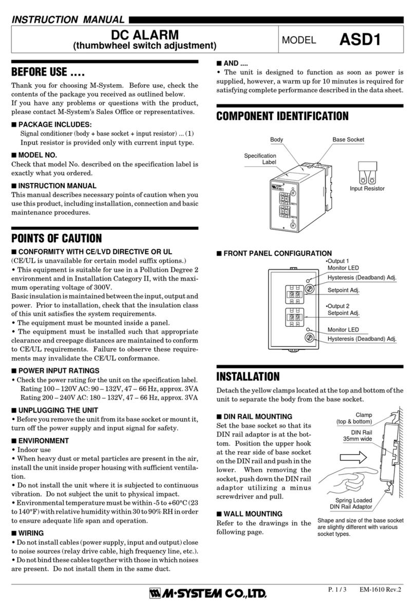
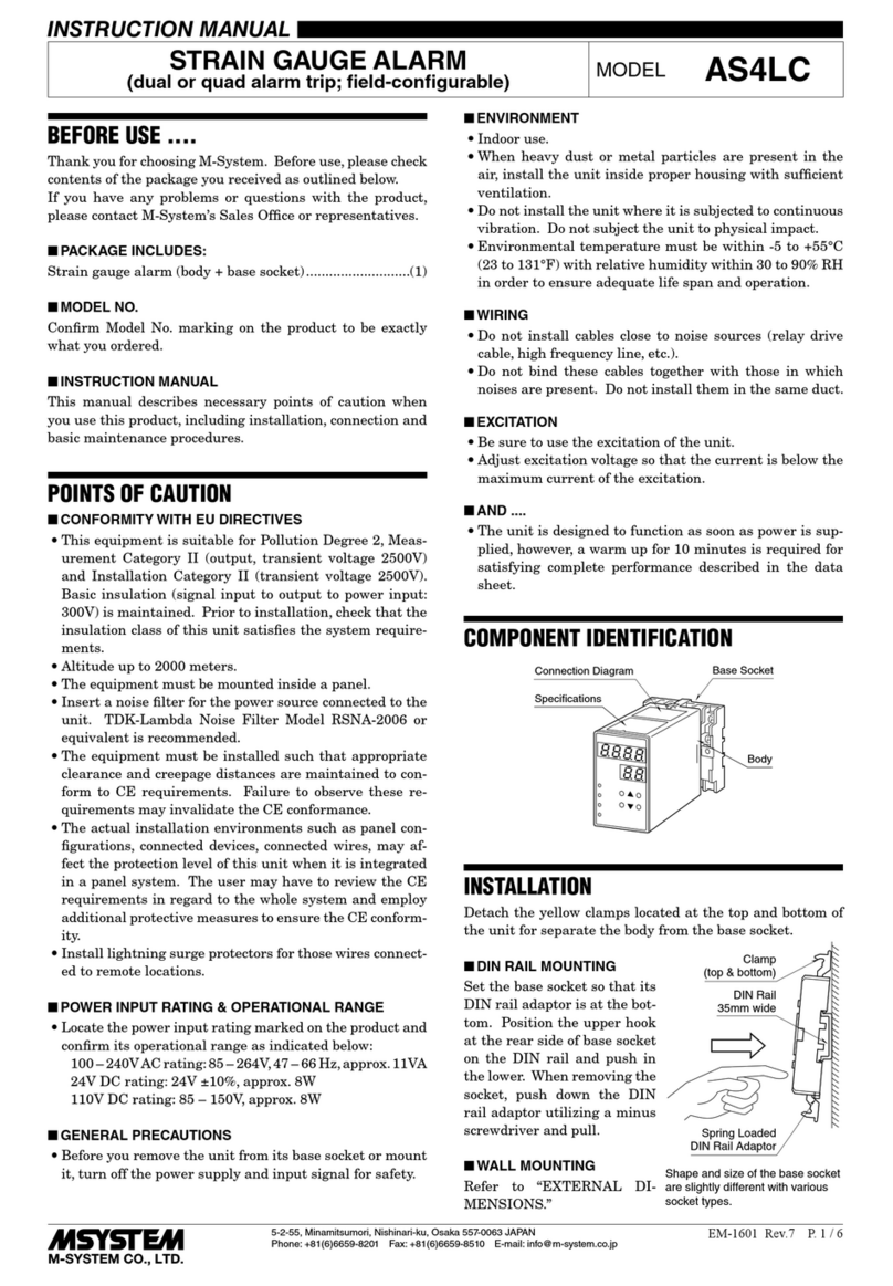
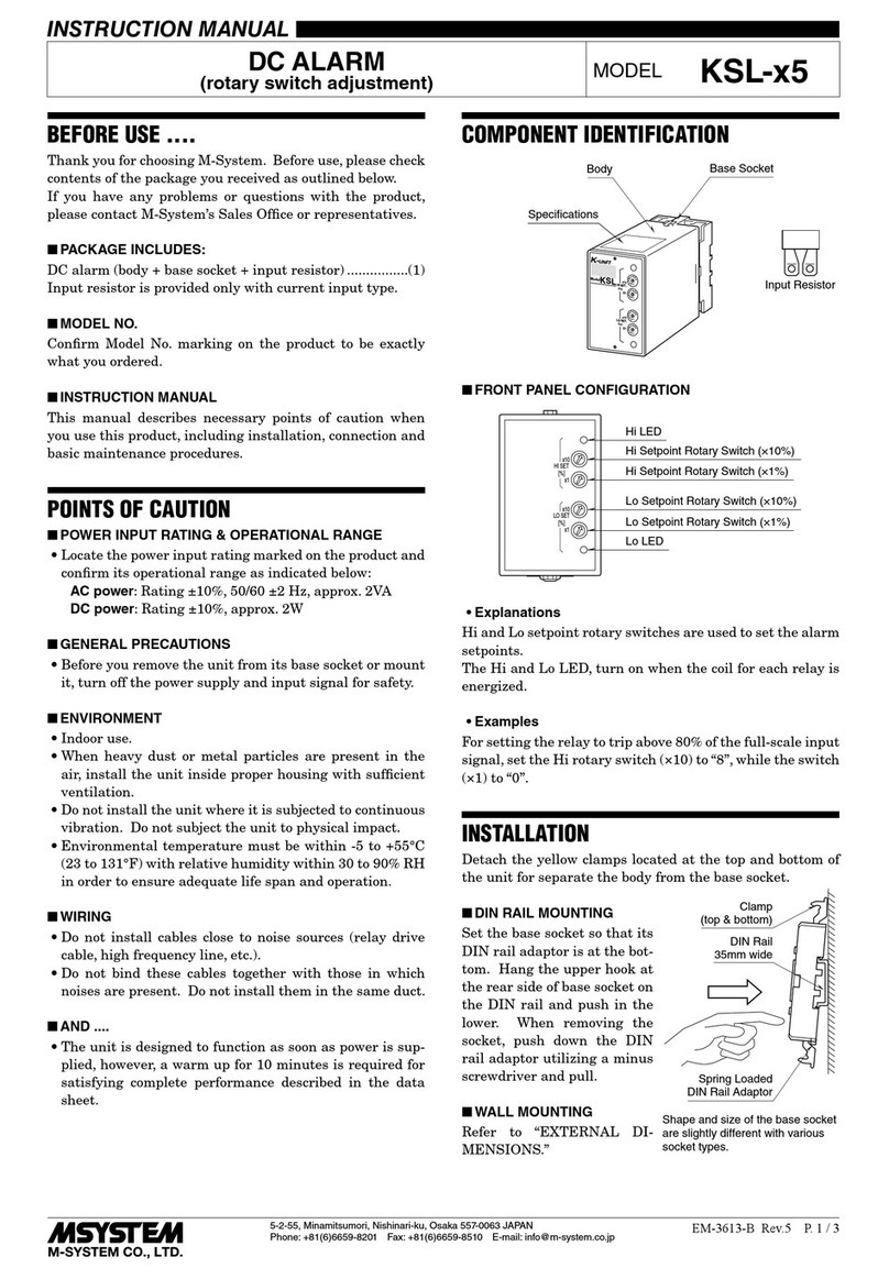
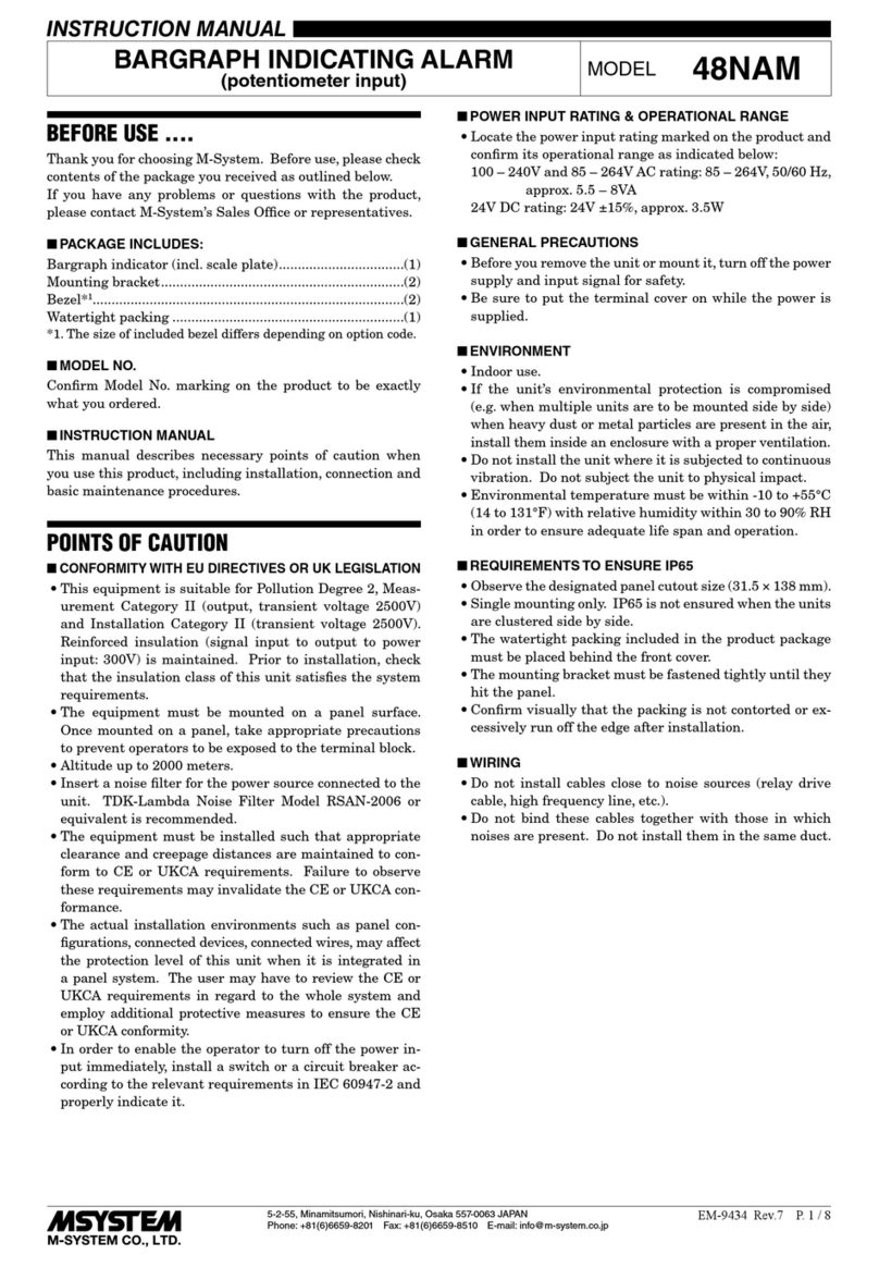
manuals.online logo
Brands
  1. Home
  2. •
  3. Brands
  4. •
  5. M-system
  6. •
  7. Security System
  8. •
  9. M-system AS User manual

M-system AS User manual

AS
P. 1 / 3 EM-1611-A Rev.6
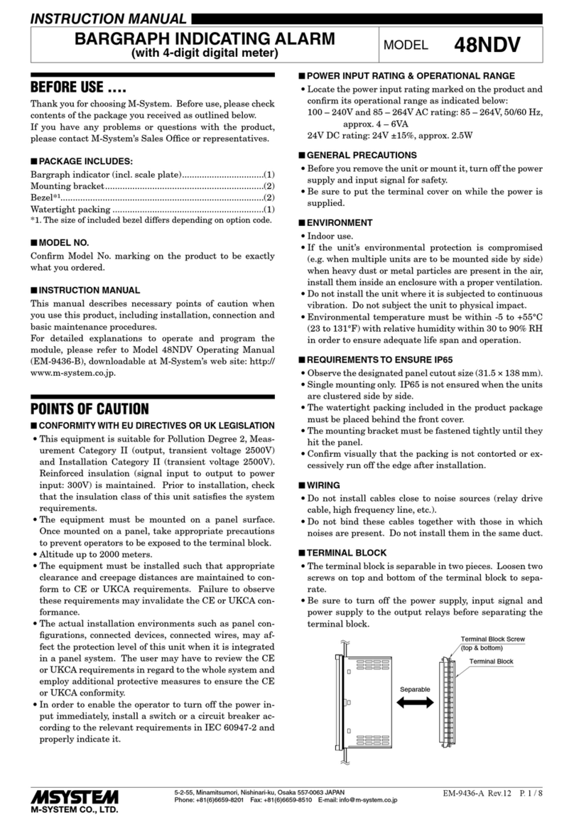
BEFORE USE ....
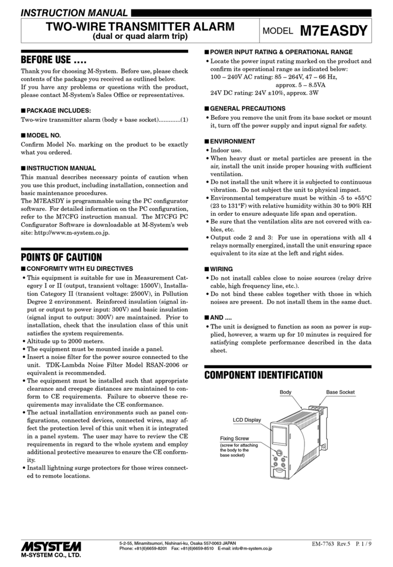
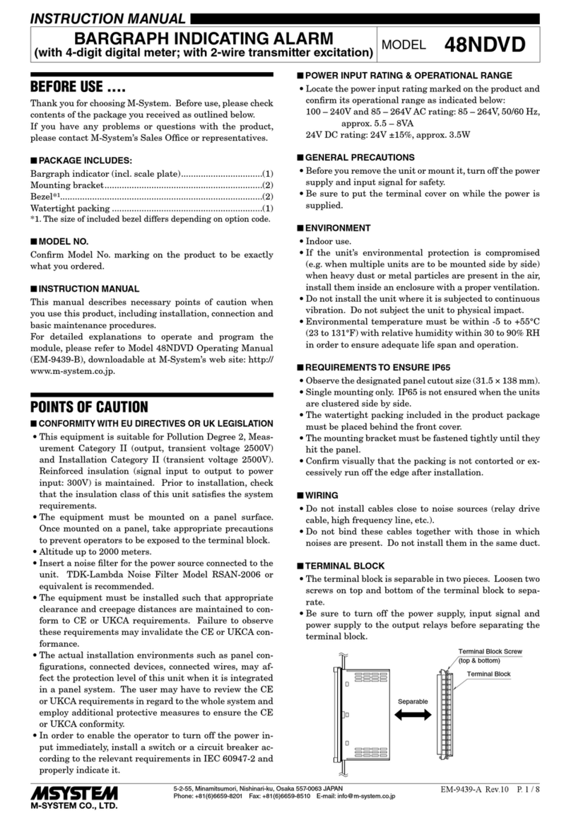
Thank you for choosing M-System. Before use, check the
package you received as below.
If you have any problems or questions with the product,
please contact M-System’s Sales Office or representatives.
■ PACKAGE INCLUDES:
Signal conditioner (body + base socket + input resistor)
(1)
Input resistor is provided only with current input type.
■ MODEL NO.
Check that model No. described on specification label is
exactly what you ordered.
■ INSTRUCTION MANUAL
This manual describes necessary points of caution when you
use this product, installation, connection and basic mainte-
nance procedures.
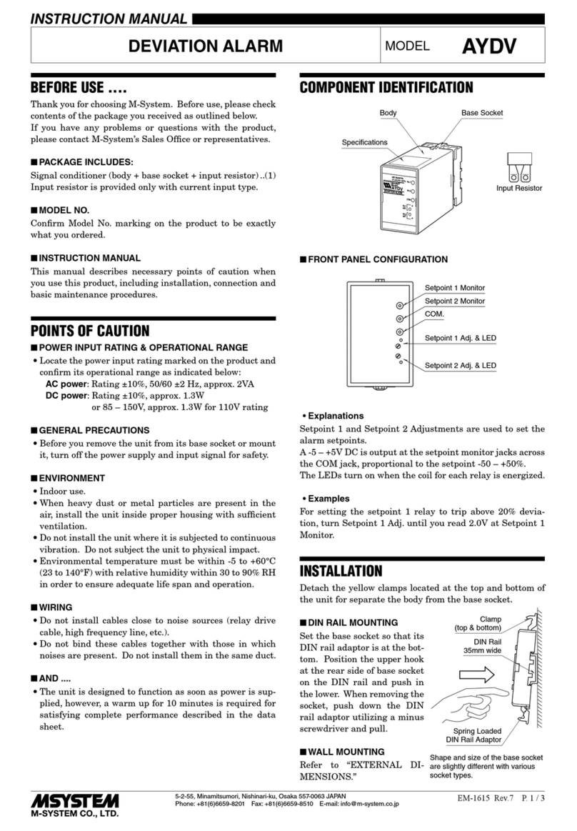
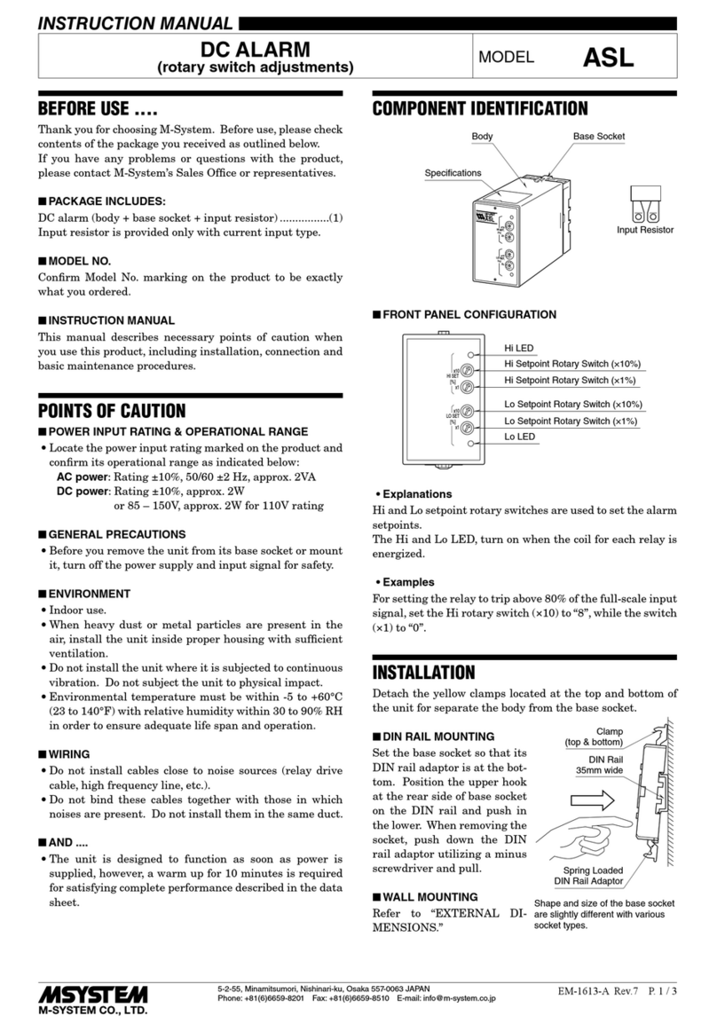
COMPONENT IDENTIFICATION
INSTRUCTION MANUAL
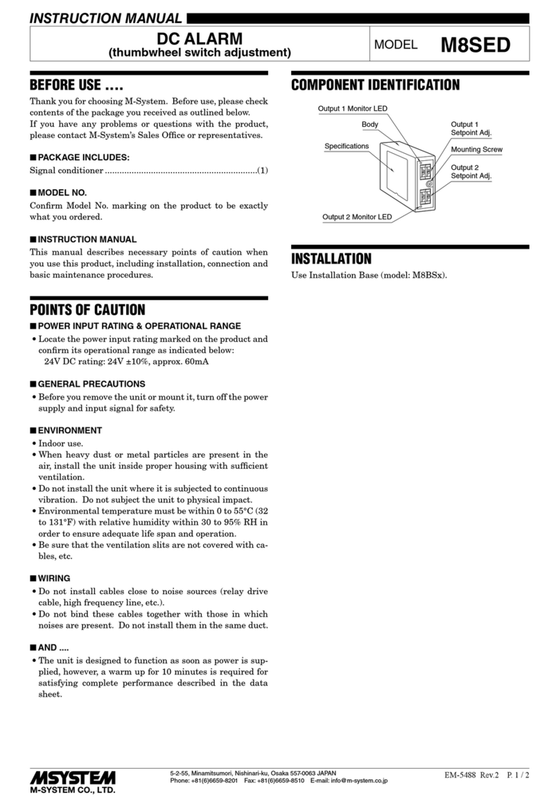
MODEL AS
DC ALARM
Input Resistor
• Hi Adjustment: Used for adjusting Hi setpoint.
• Lo Adjustment: Used for adjusting Lo setpoint.
• Hi LED: Turns on in a tripped condition.
• Lo LED: Turns on in a tripped condition.
• Hi Setpoint Monitor (+):
Outputs 0 – 10V DC proportional to the setpoint 0 – 100%.
(ex: Set to 8V when you need output ON with input 80% or
more.)
• Lo Setpoint Monitor (+):
Outputs 0 – 10V DC proportional to the setpoint 0 – 100%.
(ex: Set to 2V when you need output ON with input 20% or
less.)
• Common (–): Used for setpoint monitors.
INSTALLATION
Detach the yellow clamps lo-
cated at the top and bottom of
theunitforseparatingthebody
from the base socket.
■ DIN RAIL MOUNTING
Set the base socket so that its
DIN rail adaptor is at the bot-
tom. Position the upper hook
at the rear side of base socket
on the DIN rail and push in the
lower. When removing the
socket, push down the DIN rail
adaptorutilizingascrewdriver
(–) and pull.
■ WALL MOUNTING
Refer to the drawings in the following page.
Clamp
(top & bottom)
DIN Rail
35mm wide
Spring Loaded
DIN Rail Adaptor
Shape and size of the base socket
are slightly different with various
socket types.
AS
M•UNIT
Model
DC ALARM
0–100%
(0–10VDC)
SET MONITOR
SET
HI
LO
COM
LO
HI
Body
Specification
Label
Base Socket
Lo LED
Hi LED
Lo Adj.
Hi Adj.
Hi Setpoint Monitor
Lo Setpoint Monitor
COM.
■ FRONT PANEL CONFIGURATION
AS
P. 2 / 3 EM-1611-A Rev.6
TERMINAL CONNECTIONS
Connect the unit as in the diagram below or refer to the connection diagram label on the front of the unit.
When an input resistor is provided with the module, attach it together with input wiring to the input screw terminals.
■ DIMENSIONS mm (inch)
■CONNECTION DIAGRAM ■TERMINAL ASSIGNMENTS mm (inch)
3456
2187
80 (3.15)
50 (1.97) 103 (4.06)
123 (4.84) [3.3 (.13)]
80 (3.15)
20
(.79)
35.4 (1.39)
40 (1.57)
50 (1.97)
7.8 (.31)
CLAMP
(top & bottom)
DIN RAIL
35mm wide
2–4.5 (.18) dia.
MTG HOLE
15 (.59) deep
8–M3.5
SCREW
•When mounting, no extra space is needed between units.
+
–
+
–
*
*Input shunt resistor attached for current input.
INPUT
3
HI OUTPUTR
4
1
2
+
–
LO OUTPUT
5
6
U(+)
V(–) POWER
7
8
56
2187
34
12 (.47)
INPUT RESISTOR
(model: REM)
Input shunt resistor attached
for current input.
AS
P. 3 / 3 EM-1611-A Rev.6
CHECKING
1) Terminal wiring: Check that all cables are correctly
connected according to the connection diagram.
2) Power input voltage: Check voltage across the terminal 7
–␣ 8 with a multimeter.
3) Input: Check that the input signal is within 0 – 100% of
the full-scale.
4) Relay operations: Confirm that the relays operate prop-
erly referring to the figure below.
5) Output load: Check the output load corresponds to the
table below.
For maximum relay life with inductive load, external
protection is recommended.
ALARM RELAY OPERATIONS
Trip Operation in Power Failure
•Output Code: 1, 2, 4: both relays turn OFF
•Output Code: 3: both relays turn ON
POINTS OF CAUTION
■ GENERAL
• Before you remove the unit from its base socket or mount it,
turn off the power supply and input signal for safety.
■ ENVIRONMENT
• When heavy dust or metal particles are present in the air,
install the unit inside proper housing and ventilate it.
• Do not install the unit where it is subjected to continuous
vibration. Do not apply physical impact to the unit.
• Environmental temperature must be within -5 to +60°C (23
to140°F) with relativehumidity within 30to 90% RH inorder
to ensure adequate life span and operation.
■ WIRING
• Do not install cables (power supply, input and output) close
to noise sources (relay drive cable, high frequency line, etc.).
• Do not bind these cables together with those in which noises
are present. Do not install them in the same duct.
■ AND ....
• The unit is designed to function as soon as power is
supplied, however, a warm up for 10 minutes is required for
satisfying complete performance described in the data sheet.
MAINTENANCE
Regular calibration procedure is explained below:
■ CALIBRATION
Warm up the unit for at least 10 minutes.
• Hi Setpoint
Increasethe input signalfroma value lowerthan the setpoint
and check that the trip point remains within the accuracy
described in the data sheet.
• Lo Setpoint
Decrease the input signal from a value higher than the
setpoint and check that the trip point remains within the
accuracy described in the data sheet.
When the trip points are out of tolerance, contact M-System’s
Sales Office or local representatives.
0 50 100▲
Input
(%) Lo Setpoint ▲
Hi Setpoint
Hi Output
(1–2)ON
Lo Output
(5–6)ON
0 50 100▲
Input
(%) Lo Setpoint ▲
Hi Setpoint
Hi Output
(1–2)ON
Lo Output
(5–6)ON
•Output Code : 1, 2, 4
•Output Code : 3
OUTPUT LOAD RESISTANCE
Open collector 50V DC @100mA
Relay 380V AC @100VA
125V DC @30W
SSR 60 – 280V AC @0.1 – 1A
M-SYSTEM WARRANTY
M-System warrants such new M-System product which it manufactures to be free from defects in materials and workmanship during the 36-month period following the date that such
productwasoriginallypurchasedifsuchproducthasbeenusedundernormaloperatingconditionsandproperlymaintained,M-System'ssoleliability,andpurchaser'sexclusiveremedies,
under this warranty are, at M-System's option, the repair, replacement or refund of the purchase price of any M-System product which is defective under the terms of this warranty. To
submit a claim under this warranty, the purchaser must return, at its expense, the defective M-System product to the below address together with a copy of its original sales invoice.
THIS IS THE ONLY WARRANTY APPLICABLE TO M-SYSTEM PRODUCT AND IS IN LIEU OF ALL OTHER WARRANTIES, EXPRESS OR IMPLIED, INCLUDING ANY IMPLIED
WARRANTIES OF MERCHANTABILITY OR FITNESS FOR A PARTICULAR PURPOSE. M-SYSTEM SHALL HAVE NO LIABILITY FOR CONSEQUENTIAL, INCIDENTAL OR
SPECIAL DAMAGES OF ANY KIND WHATSOEVER.
M-System Co., Ltd., 5-2-55, Minamitsumori, Nishinari-ku, Osaka 557-0063 JAPAN, Phone: (06) 6659-8201, Fax: (06) 6659-8510, E-mail: [email protected]
Other M-system Security System manuals

M-system 48NDVD User manual

M-system

M-system 48NDVD User manual

M-system 48NDVA User manual

M-system

M-system 48NDVA User manual

M-system ASD1 User manual

M-system

M-system ASD1 User manual

M-system AS4V User manual

M-system

M-system AS4V User manual

M-system AS4T User manual

M-system

M-system AS4T User manual

M-system KS2TR2 User manual

M-system

M-system KS2TR2 User manual

M-system AS4CT User manual

M-system

M-system AS4CT User manual

M-system M1EAXV-2 User manual

M-system

M-system M1EAXV-2 User manual

M-system 48NDM User manual

M-system

M-system 48NDM User manual

M-system M2AS User manual

M-system

M-system M2AS User manual

M-system KSE-1 User manual

M-system

M-system KSE-1 User manual

M-system 48NAM User manual

M-system

M-system 48NAM User manual

M-system Mini-M M2SED User manual

M-system

M-system Mini-M M2SED User manual

M-system KSL2 User manual

M-system

M-system KSL2 User manual

M-system ASL User manual

M-system

M-system ASL User manual

M-system M7EASDY User manual

M-system

M-system M7EASDY User manual

M-system 48NDT User manual

M-system

M-system 48NDT User manual

M-system AYDV User manual

M-system

M-system AYDV User manual

M-system 48NAT User manual

M-system

M-system 48NAT User manual

M-system AS4R User manual

M-system

M-system AS4R User manual

M-system KS2V3 User manual

M-system

M-system KS2V3 User manual

M-system KSE-x2 User manual

M-system

M-system KSE-x2 User manual

M-system M6DXAR User manual

M-system

M-system M6DXAR User manual

M-system M1EAXV-1 User manual

M-system

M-system M1EAXV-1 User manual

Popular Security System manuals by other brands

Dwyer Instruments AN24 Series instruction manual

Dwyer Instruments

Dwyer Instruments AN24 Series instruction manual

Lorex SG17L7584 instruction manual

Lorex

Lorex SG17L7584 instruction manual

Chore-Time Broadcaster Installation and Operators Instruction Manual

Chore-Time

Chore-Time Broadcaster Installation and Operators Instruction Manual

QOLSYS IQ PANEL installation guide

QOLSYS

QOLSYS IQ PANEL installation guide

SILENT KNIGHT RA-100 Installation

SILENT KNIGHT

SILENT KNIGHT RA-100 Installation

Toyota TVSS IIIB installation instructions

Toyota

Toyota TVSS IIIB installation instructions

Optex Genesys 824 R owner's manual

Optex

Optex Genesys 824 R owner's manual

jcm-tech CONNECT4 CC user manual

jcm-tech

jcm-tech CONNECT4 CC user manual

JAI VIS-CAM System installation manual

JAI

JAI VIS-CAM System installation manual

O.Y.L. Technology Avantis AX1 user manual

O.Y.L. Technology

O.Y.L. Technology Avantis AX1 user manual

Smanos WS-20 user manual

Smanos

Smanos WS-20 user manual

RHINO 832 Installation & operation manual

RHINO

RHINO 832 Installation & operation manual

Apollo 33 404 Installation guides

Apollo

Apollo 33 404 Installation guides

Trend Micro TippingPoint TPS 440T manual

Trend Micro

Trend Micro TippingPoint TPS 440T manual

Motoman XRC Maintenance manual

Motoman

Motoman XRC Maintenance manual

Interlogix ZeroWire user manual

Interlogix

Interlogix ZeroWire user manual

Venitem ATX2/S manual

Venitem

Venitem ATX2/S manual

Cobra P1703-141 manual

Cobra

Cobra P1703-141 manual

manuals.online logo
manuals.online logoBrands
  • About & Mission
  • Contact us
  • Privacy Policy
  • Terms and Conditions

Copyright 2025 Manuals.Online. All Rights Reserved.