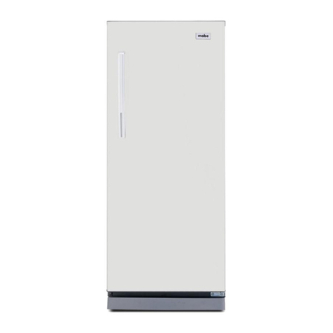
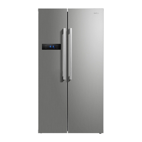
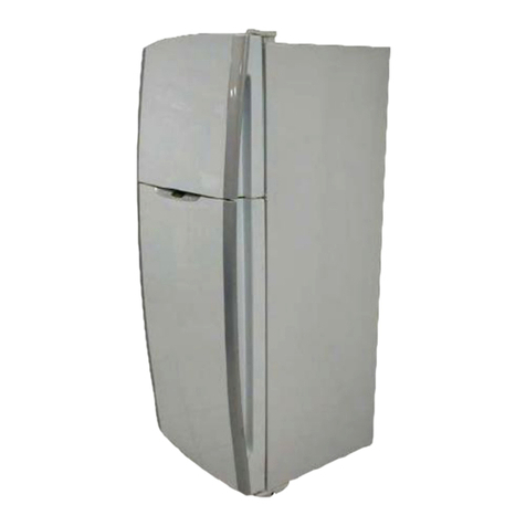
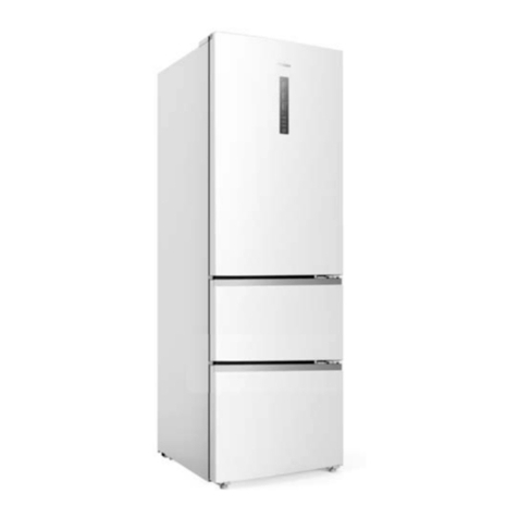
mabe ITV085ICER User manual

SERVICE MANUAL
Model:
: ITV085ICER
: ITV095ICER
: ITV110ICER
: ITV120ICER
Contents
Specifications -------------------------1
Circuit Diagram-----------------------4
Refrigerant Circuit--------------------7
Replacement of Parts---------------8
Control function-----------------------18
Trouble shooting----------------------23

Page 1
PRINTED : JAN’2015 REF NO. SM7715010-01-11
SERVICE MANUAL Refrigerator
1 Specifications
1-1) Specific parts for specific countries
Item
No. Model Destination
Power Source
(Voltage-ac / Hz) Power Cord
1. ITV085ICER Philippines(PH) 220 / 50 B2
2. ITV095ICER Philippines(PH) 220 / 50 B2
3. ITV110ICER Philippines(PH) 220 / 50 B2
4. ITV120ICER Philippines(PH) 220 / 50 B2

Page 2
PRINTED : JAN’2015 REF NO. SM7715010-01-11
1-2) Product
Model ITV085ICER ITV095ICER ITV110ICER ITV120ICER
Classification 2 Doors No Frost
Temperature Control Electronic control
Defrost System Automatic
Drain System Automatic (Heat by transfer from the Condenser)
Evaporator Fined Evaporator
Condenser Pipe Condenser
Insulation
Cabinet Rigid Polyurethane Foam ( Cyclopentane )
Freezer Door Rigid Polyurethane Foam ( Cyclopentane )
Refrigerator Door Rigid Polyurethane Foam ( Cyclopentane )
Refrigerant R-600A R-600A R-600A R-600A
Refrigerant Charge (g.) 46 46 64 64
Overall Dimension (WxDxH (mm.)) 545 x 645 x 1573.5 545 x645x1678.5 595x 677 x 1650.5 595 x677x1754.5
Packing Dimension (WxDxH (mm.)) 580 x 726 x 1674.5 580x726x1779.5 630x755x1751.5 630x755x1846.5
Net Weight (kg.) 50 52 55 59
Gross Weight (kg.) 56 58 61 65
1-3) Electrical Parts
Compressor Model VNX113Y
Electrical data Input: 220-240V 50-60Hz
Connection Connector CN6 on main PCB
Between circuit 1(BL) – 3 (BR)
Resistance value V-U : 7.3 Ω
V-W : 7.3Ω
U-W : 7.3Ω
Inverter control box Model MZ-259-02R220C
Electrical data Input : 220-240 VAC 50Hz 1.6A 1PH
Output: 70-200V DC 40-150Hz 1.5A 3PH
Connection Connector CN8 on main PCB <signal>
Between circuit 1(Y) – 4 (W)
Defrost heater Model -
Electrical data 130W 220V R: 372.3Ω(HRF-315FI, 340FI)
120W 220V R: 403.3Ω(HRF-245FI, 265FI)
Connection Connector CN4 on PCB
Between circuit 1(R) – 5 (B)

Page 3
PRINTED : JAN’2015 REF NO. SM7715010-01-11
1-3) Electrical Parts
Freezer Fan motor Model DG8-013U12M
Electrical data 9 V DC 0.6W
Connection Connector CN9 on PCB
Between circuit 1(Y) – 2 (BL)
Thermal fuse Model SF76E
Electrical data 10A 250V
cut-off temperature 77 C
Connection Series connection with Defrosting heater
Defrost sensor Model ‐<NTCThermister>
Electrical data Resistance value
0℃:6.0KΩ
25℃:2.18KΩ
Connection Connector CN7 on PCB
Between circuit 3(G) – 5 (B)
R-Sensor Model
‐<NTCThermister>
Electrical data Resistance value
0℃:6.0KΩ
25℃:2.18KΩ
Connection Connector CN7 on PCB
Between circuit 4(B) – 6 (W)
Ambient Sensor Model ‐<NTCThermister>
Electrical data Resistance value
0℃:6.0KΩ
25℃:2.18KΩ
Connection Connector CN11 on PCB
Between circuit 1(W) – 3 (W)
R-Volume Model -
Electrical data Volume resistance 10 KΩat Center position
Connection Connector CN7 on PCB
Between circuit 1(Y) – 2 (W)
R-LED PCB Model -
Electrical data 12V DC
Connection Connector CN5 on PCB
Between circuit 1(P) – 4 (GR)
Door switch Model D3D-211
Electrical data 250V AC 0.5A T55
Connection Connector CN7 on PCB Between circuit 7(P) –8(W)

Page 4
PRINTED : JAN’2015 REF NO. SM7715010-01-11
2 Circuit Diagram
Model: ITV085ICER, ITV095ICER,ITV110ICER, ITV120ICER (Inverter compressor)
2-1 Circuit Diagram

Page 5
PRINTED : JAN’2015 REF NO. SM7715010-01-11
2-2 Reference wiring diagram

Page 6
PRINTED : JAN’2015 REF NO. SM7715010-01-11
2.3 Rating plate
Model : ITV085ICER
Total Volume : 242 L , 8.5(Cu.ft)
Voltage : 220 V
Frequency : 50 Hz
Current : 0.9A
Power Input : 135 W
Defrosting Input : 120 W
Refrigerant R600 A : 46 g
Net Weight : 50 kg
Model : ITV095ICER
Total Volume : 264 L , 9.3(Cu.ft)
Voltage : 220 V
Frequency : 50 Hz
Current : 0.9A
Power Input : 135 W
Defrosting Input : 120 W
Refrigerant R600 A : 46 g
Net Weight : 52 kg
Model : ITV110ICER
Total Volume : 305 L , 10.8 (Cu.ft)
Voltage : 220 V
Frequency : 50 Hz
Current : 0.9 A
Power Input : 135 W
Defrosting Input : 130 W
Refrigerant R600 A : 64 g
Net Weight : 55 kg
Model : ITV120ICER
Total Volume : 335 L , 11.8 (Cu.ft)
Voltage : 220 V
Frequency : 50 Hz
Current : 0.9 A
Power Input : 135 W
Defrosting Input : 130 W
Refrigerant R600 A : 64 g
Net Weight : 59 kg

Page 7
PRINTED : JAN’2015 REF NO. SM7715010-01-11
3 Refrigerant Circuit

Page 8
PRINTED : JAN’2015 REF NO. SM7715010-01-11
4 Replacement of Parts
•Unplug the power cord before servicing.
Part Name
Frz Fan blade.
Operating Procedure
1. Remove Ice Storage Box. 2. Remove Ice Cube Tray Assy. 3. Remove Shelf F.
4. Dig Cover Cap out. 5. Release screws at FF Cover 6.Lift Cover and Fan Cover out.
7. Dig Spring
8. Lift Spring..
9. Pull out Fan Blade from Fan Motor
10. After replacing Fan Blade, reverse the steps above.

Page 9
PRINTED : JAN’2015 REF NO. SM7715010-01-11
Part Name
Fan Motor.
Operating Procedure
- Follow step 1-10 of replacing Fan Blade.
1. Lift Plate MTG Motor out. 2. Take out socket of Fan Motor. 3. Release screw at Cover A.
4. Pull Cover A from Plate MTG Motor.
5. Pull out Fan Motor from Plate MTG
Motor.
6. After replacing Fan Motor, reverse the
steps above.

Page 10
PRINTED : JAN’2015 REF NO. SM7715010-01-11
Part Name
Defrost Sensor
Operating Procedure
- Follow step 1-10 of replacing Fan Blade.
-Follow step 1-2 of replacing Fan Motor.
1. Take out socket of Defrost sensor. 2. Cut out Cable Tie from Evaporator
tube.
3. Remove Al tape.
4. Pull Defrost Sensor from Evaporator
tube.
5. After replacing Bimetal Thermo, reverse the steps above.

Page 11
PRINTED : JAN’2015 REF NO. SM7715010-01-11
Part Name
Thermal Fuse.
Operating Procedure
- Follow step 1-10 of replacing Fan Blade.
-Follow step 1-2 of replacing Fan Motor.
1. Take out socket of Thermal Fuse. 2. Cut out Cable Tie from Evaporator
tube.
3. Pull Thermal Fuse from Evaporator
tube.
4. After replacing Thermal Fuse, reverse the steps above.

Page 12
PRINTED : JAN’2015 REF NO. SM7715010-01-11
Part Name
Glass Tube Heater.
Operating Procedure
- Follow step 1-10 of replacing Fan Blade.
- Follow step 1-2 of replacing Fan Motor.
1. Take out socket of Glass Tube Heater. 2. Take out socket of Glass Tube Heater. 3. Remove aluminium tape that cover
electrical wire.
4. Hold and lift Evaporator up. 5. Hold Glass Tube Heater at the rubber
connector.
6. After replacing Glass Tube Heater,
reverse the steps above.

Page 13
PRINTED : JAN’2015 REF NO. SM7715010-01-11
Part Name
LED LAMP.
Operating Procedure
1. Pull out Chiller. 2. Remove all Glass Shelf. 3. Remove Lamp Cover .
4. Release screws.
5. Pull out socket.
6.Remove LED Lamp.
7. After replacing LED lamp, reverse the steps above.

Page 14
PRINTED : JAN’2015 REF NO. SM7715010-01-11
Part Name
Ref Sensor.
Operating Procedure
- Follow step 1-6 of replacing Chill LED Lights.
1. Release screws. 2. Pull out Multi-Duct Assy 3. Pull out socket.
4. Pull out Multi-Duct Ins. 5. Remove all paper tape.
6. Remove all Seal.
7. Remove all Sensor.8. After replacing Sensor, reverse the
steps above.

Page 15
PRINTED : JAN’2015 REF NO. SM7715010-01-11
Part Name
Volume Assy.
Operating Procedure
- Follow step 1-6 of replacing Chill LED Lights.
- Follow step 1-4 of replacing Ref sensor.
1. Pull out Socket. 2. Release screws. 3. Remove all Volume Assy.
4. Pull out Socket.
5. After replacing Volume Assy, reverse the steps above.

Page 16
PRINTED : JAN’2015 REF NO. SM7715010-01-11
Part Name
Elec. Component Ass’y(Main PCB).
Operating Procedure
1. Release screws that Cover B. 2. Pull out Rear Cover B. 3. Release screws that Elec. Component
Ass’y(Main PCB)
4. Pull out Socket.
5. Pull out Elec. Component Ass’y(Main
PCB)
6. After replacing Elec. Component Ass’y., reverse the steps above.

Page 17
PRINTED : JAN’2015 REF NO. SM7715010-01-11
Part Name Inverter model
1. Remove inverter box. 2. . pull out socket. 3. Release screws that inverter box.
4. pull out socket electrical wires from
inverter box.
5. After Replacing inverter model, reverse the steps above.

Page 18
PRINTED : JAN’2015 REF NO. SM7715010-01-11
5 Control Function
1. Temperature control of the refrigerator compartment
Item Explanation
Outline
To control the temperature of the refrigerator compartment, the
compressor is tuned ON/OFF according to R sensor temperature and R
volume.
Compressor safety time Normal:5min After defrosting: 3min (when SHORT pin is shorted: 1sec)
Temperature control
(Setting:Mid) From -1.5oC to 1.5oC
Range of volume Adjusted in the range of from -2.5 to 2.5.
Differential
3degrees
(For details, refer 2. Temperature specification of the refrigerator
compartment)
Just after
power supply ON
Keep compressor forced ON for 5min. (when SHORT pin is shorted:
1sec)
When sensors
are abnormal
When R sensor / D sensor is disconnected or detect short circuit,
turn the compressor OFF compulsively.
Under defrosting The compressor is OFF.
Minimum ON time If compressor is turned ON, it is not turned OFF within 5min.
(when SHORT pin is shorted: 1sec)
But Manual DEF is prior.
Adjustment process in
low ambient temperature
When the compressor continues OFF for 1hours,
keep compressor forced ON for 9min.
2. Temperature specification of the refrigerator compartment
ON OFF DIFF ON OFF DIFF ON OFF DIFF
Normal Mode
( AT>=23
o
C ) 4 1 3 1.5 -1.5 3 -1 -4 3
ON点 OFF点 DIFF ON点 OFF点 DIFF ON点 OFF点 DIFF
Low Ambient
Temperature Mode 2 -1 3 1.5 -1.5 3 -1 -4 3
( AT<23
o
C )
F
ridge Setting: Mi
n
F
ridge Setting: Mi
d
F
ridge Setting: Ma
x

Page 19
PRINTED : JAN’2015 REF NO. SM7715010-01-11
3. Original value of compressor frequency and freezer fan voltage
4. Inverter control
Item Explanation
Outline To keep required cooling capacity, change the compressor frequency.
Compressor driving
frequency
under startup
Step1) Drive 25Hz for 1min
Step2) Drive 46Hz for 2min (When control to 50Hz or more)
When control to less than 50Hz, control to each target value after
Step1.
Compressor driving
frequency
before stopping
Step1) Decrease compressor frequency to 35Hz
Step2) Drive 35Hz for 3sec
Note: This function is controlled by Inverter-PCB
When TEST pin
is shorted
The compressor is operating continuously while TEST pin is shorted.
Ignore R sensor temperature. DEF can't startup.
Compressor frequency:50Hz
Under pulldown control Starting up as normally startup driving.
Compressor frequency:50Hz
Step-up mode
When the compressor is driven 120min or more (In case of first time
compressor ON before defrosting, 180min or more), increase frequency
by every 30min.
Step-up mode shall be finished when the compressor OFF.
Step-up frequency 25Hz => 30Hz => 36Hz => 40Hz => 50Hz
After defrosting
Change the method of frequency control at first time compressor ON
after defrosting finish.
Step1) Drive 25Hz for 1min
Step2) Drive 46Hz for 2min
Step2) Drive 50Hz for 2min
Control to each target value after Step3.
Relationship between
Step-up mode and
defrosting
If Step-up mode is running at just before defrosting, store the frequency
value
and restore it when aftre defrosting control step3.
Priority 1.Start up 2.Pulldown 3.TEST pin 4.Step-up mode 5.Normal
High Ambient
Temperature Mode2
( AT>37
o
C )
High Ambient
Temperature Mode1
( 37
o
C>AT>=34
o
C )
Normal Mode
( 34
o
C>AT>=23
o
C )
Low Ambient
Temperature Mode
( AT<23
o
C )
Compressor Freq:40Hz
Freezer Fan Voltage:8V
Compressor Freq:40Hz
Freezer Fan Voltage:8V
Compressor Freq:40Hz
Freezer Fan Voltage:8V
Fridge Setting: Min Fridge Setting: Mid Fridge Setting: Max
Compressor Freq:50Hz
Freezer Fan Voltage:10V
Compressor Freq:36Hz
Freezer Fan Voltage:9V
Compressor Freq:25Hz
Freezer Fan Voltage:8V
Compressor Freq:50Hz
Freezer Fan Voltage:10V
Compressor Freq:40Hz
Freezer Fan Voltage:10V
Compressor Freq:30Hz
Freezer Fan Voltage:9V
Compressor Freq:36Hz
Freezer Fan Voltage:9V
Compressor Freq:50Hz
Freezer Fan Voltage:10V
Compressor Freq:50Hz
Freezer Fan Voltage:10V
This manual suits for next models
3
Table of contents
Other mabe Refrigerator manuals

mabe
mabe MTM482SENSS0 User manual

mabe
mabe RMI2160XSAB0 User manual

mabe
mabe RMV21WIM User manual

mabe
mabe MSC504SORBS0 User manual

mabe
mabe serviplus SEDNA ESTILO User manual

mabe
mabe RMS1540Z User manual

mabe
mabe RMF0411YINB0 User manual

mabe
mabe RMC425NESY0 User manual
mabe
mabe MAV060IAERWW User manual
mabe
mabe RMC215NEWWY0 User manual

mabe
mabe RMI1851XSAB0 User manual

mabe
mabe RMV21WI User manual
mabe
mabe ESTILO User manual

mabe
mabe RMF0411PYMN0 User manual

mabe
mabe MTV085ICER User manual

mabe
mabe RMC090NESY0 User manual

mabe
mabe RMB32YLCS0 User manual

mabe
mabe FMM300UESX0 User manual
mabe
mabe RMC215NEWWY1 User manual

mabe
mabe RM04Y04RM43U User manual