mabe RMB32YLCS0 User manual

Order No. Ref1505S017V0
©2017 All right reserved. Unauthorized copying and distribution is a violation of law.
MODEL: RMB32YLCS0
SERVICE MANUAL
Refrigerator
This service information is designed for experienced repair technicians only and is not designed for use by the general public. It
dose not contain warnings and cautions to advice non-technical individuals of potential dangers in attempting to service a product.
Product powered by electricity should by serviced or repaired only by experienced professional technicians. Any attempt to service
or repair the product or products dealt with in this service information by anyone else could result in serious injury or death.
WARNING

1
1
Contents
Chapter 1 General Information .......................................................................................................................2
1-1. General Guidelines..................................................................................................................................2
1-2. Insurance test ..........................................................................................................................................2
Chapter 2 Product Feature .............................................................................................................................3
2-1. Specifications...........................................................................................................................................3
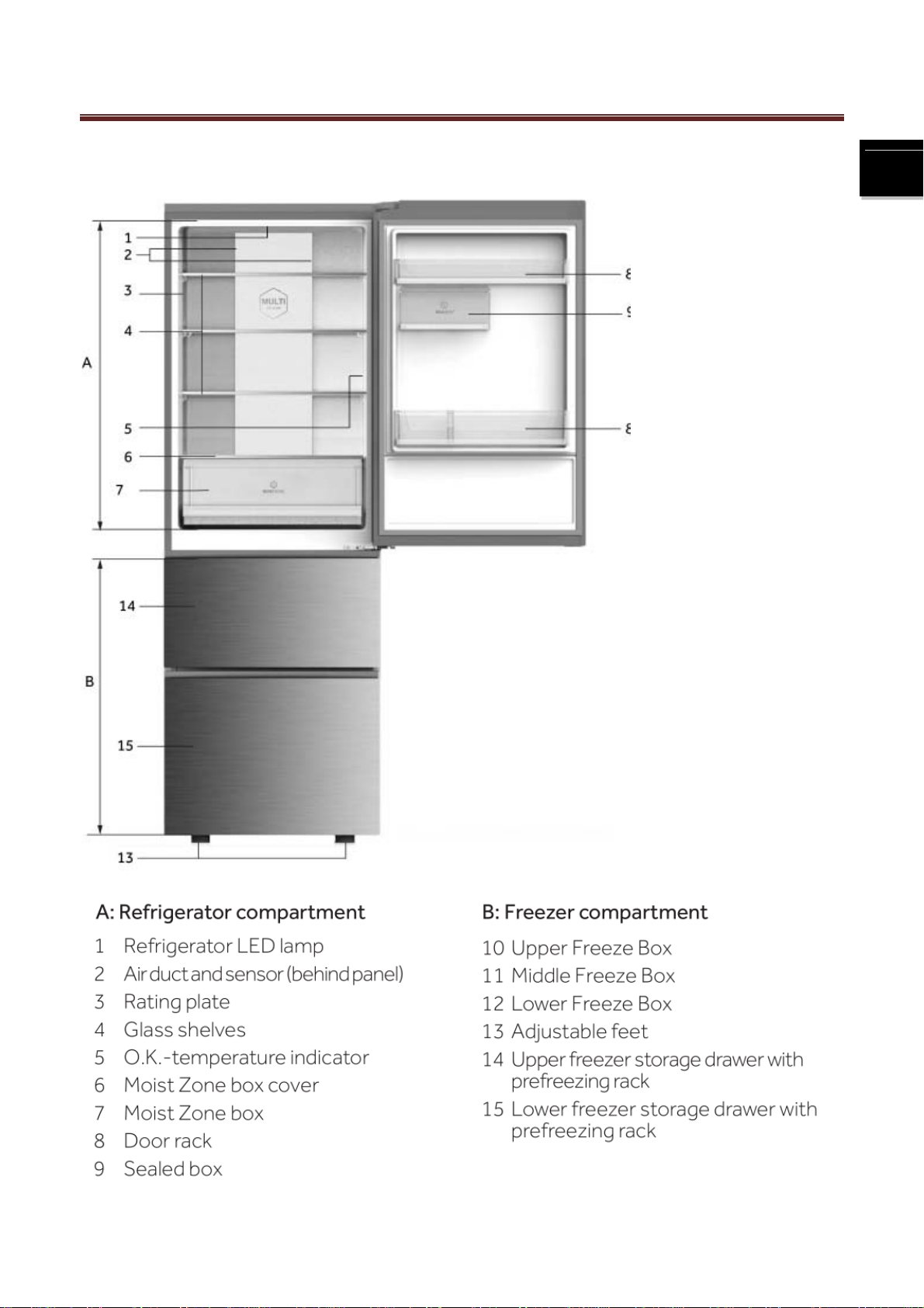
2-2. External views..........................................................................................................................................4
2-3 Space requirement....................................................................................................................................5
2-4. Main features...........................................................................................................................................5
Chapter 3 Disassembly and Installation..........................................................................................................6
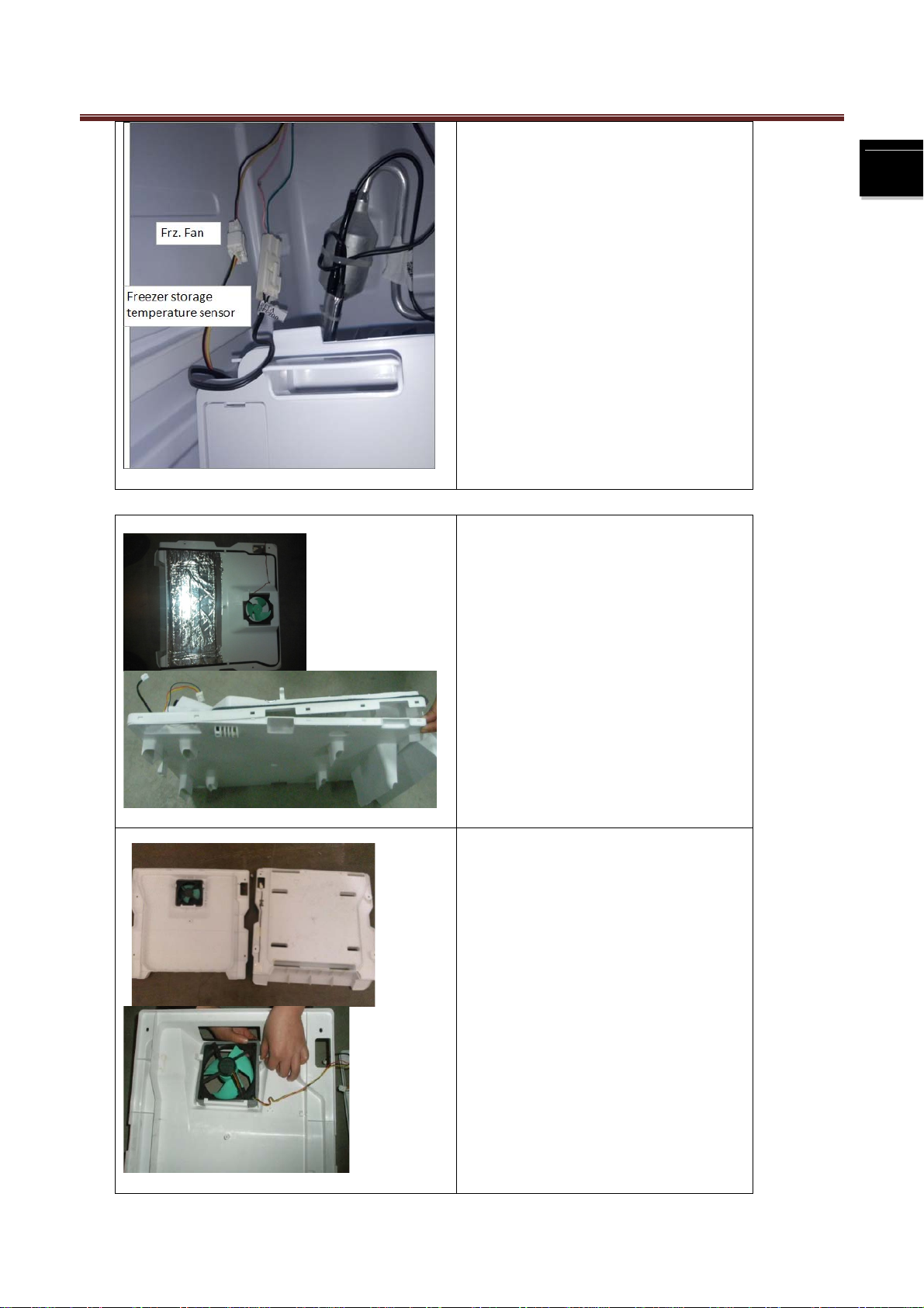
3-1 Disassembly of the assembly...................................................................................................................6
Chapter 4 System flow principle ...................................................................................................................12
4-1. Refrigeration flow chart..........................................................................................................................12
4-2 Refrigerating cycle perspective...............................................................................................................13
Chapter 5 Circuit diagram.............................................................................................................................14
5-1. Brief principle diagram...........................................................................................................................14
5-2. Main control Chart .................................................................................................................................15
5-3.Connectors ‘ location on PCB..............................................................................................................16
Chapter 6 Main Function Operating principle...............................................................................................17
6-1 Defrost system .....................................................................................................................................17
Chapter 7 Control and display system..........................................................................................................19
7-1 Control and display panel.......................................................................................................................19
7-2 Function adjustment ...............................................................................................................................19
Chapter 8 Quick check and Self-test model .................................................................................................21
8-1 Checking method of fault code.............................................................................................................21
8-2 Test mode ...............................................................................................................................................21
8-3 Demo mode ............................................................................................................................................22
8-4 Sensor layout plan..................................................................................................................................23
Chapter 9 Electrical Parts specifications.......................................................................................................24
Chapter 10 Trouble shooting.........................................................................................................................25
10-1. Symptom: No freezing.........................................................................................................................25
10-2. Symptom: no shutdown.......................................................................................................................26
10-3. Symptom: Poor freezing......................................................................................................................27
10-4. Symptom: No starting when powering on............................................................................................28
10-5. Symptom: no defrosting.......................................................................................................................29

2
2
Chapter 1 General Information
1-1. General Guidelines
When servicing, observe the original lead dress. If a short circuit is found, replace all parts which have been
overheated or damaged by the short circuit. After servicing, see to it that all the protective devices such as
insulation barriers, insulation papers shields are properly installed. After servicing, make the following leakage
current checks to prevent the customer from being exposed to shock hazards.
1) Leakage Current Cold Check
2) Leakage Current Hot Check
3) Prevention of Electro Static Discharge (ESD) to Electrostatic Sensitive
1-2. Insurance test
1. Check if there is any leak of current.
2. Cut out the power supply before the repair to avoid an electrical shock hazard.
3. In the case of a live-line test, insulating gloves should be worn to avoid potential electrical shock.
4. Confirm the rated current, voltage and capacity before testing with any kinds of instruments.
5. Watch if the upper door is open when you check something at a lower position.
6. Take out every part in the cabinet before moving the machine, especially things like panels (e.g. glass shelf).
7. Please wear intact cotton gloves when repair any parts of the evaporator, so that scratches by the sharp fins
can be avoided.
8. If there is a breakdown with the refrigeration system, please surrender the machine to the service center, else
the leaked refrigerant may pollute the atmosphere.
9. The refrigerator use AC of 220V with a frequency of 50Hz.
10. A big fluctuation of voltage (exceed the range 187~242V) may cause a start failure of the refrigerator, a
burn-out of the control panel and compressor, or an abnormal sound from the compressor in operation. In this
condition an automatic voltage regulator over 60W should be added.
11. Take care not to damage the supply line. Don’t yank at the line; pull the plug out gently from the receptacle.
Don’t press the line under the cabinet or step on it. Take care not to roll on or damage the supply line when
moves the machine from the wall.
12. In the case of leakage of inflammable gases like carbon monoxide, open the door and windows. Don’t pull out
or insert the plugs of the appliance.
13. Don’t touch the refrigeration surface of the freezing compartment when the refrigerator is in operation,
especially when your hand is wet, else you may be glued to the surface.
14. Pull out the plug of power supply during clearance or power outage. Wait at least five minutes to resume the
power supply in order to prevent damage to the compressor caused by continuous restart.

3
3
Chapter 2 Product Feature
2-1. Specifications
Picture
Model RMB32YLCS0
Basic features
Climate class SN/N/ST/T
Gross capacity l 300L
Total net capacity l 300L
Net capacity refrigerator compartment l 203L
Netcapacityfreezercompartment (total) l 98L
Freezing capacity / 24 hours kg/24 h 12kg/24 h
Energy consumption / year kWh/year 302
Energy consumption (EN153) per 24 h kWh/24 h 0.83
Max storage time by power failure Freezer h 13
Kind of coolant and weight (R134a/R600a) R600a(54g)
Key features
Cooling system: (K = Compressor / A = Absorbtion) K
Number of compressor(s) n° 1
Defrosting Fridge / Freezer (M=manual A=automatic) A/A
Control system (E = Electronic / M = Mechanical) E
NOFROST (Fridge/Freezer) Y
Ventilated (Fridgeonly) Y
Antibacteria system N
Basics datas
Unit dimensions with-out handle ( H / W / D) mm 1770/595/657
Depth with open door mm 1200
Net weight kg 68.5
Voltage / frequency 220-240 V~/ 50Hz
Input power / mains fuse (intensity) W /A 130/5

4
4
2-2. External views

5
5
2-3 Space requirement
Model
Appliance width
in mm
Appliance width
in mm
W1 W2 D1 D2
RMB32YLCS0 595 925 580 1200
2-4. Main features
1. Fully closed freezing system and drawer storage can avoid food tainting, keep cold and are
energy-saving. As warm air can't easily enter into the storage area when opening the door.
2. Cool wind but no frost: adopting fully air cooled refrigeration system, deep cooling and quick
freezing.
3. LED display: adopting dynamic LED to display the operational situation of refrigerator.
4. LED light guide plate illumination: adopting the technique of light guide plate illumination, the light is
soft, even, bright and no illumination dead angle.

6
6
Chapter 3 Disassembly and Installation
3-1 Disassembly of the assembly
3-1-1 Disassembly of top lamp
①
②
①Take the cover off with a
screwdriver;
②The whole lamp is fixed by snap
joint, and its location is shown in the
figure. Pull out the terminal of the left
lamp and remove the lamp.
3-1-2 Disassembly of freezer air duct
①
①Unscrew two bolts from the freezer
air duct with a cross screwdriver;
②As shown in the figure, pull out the
two terminals those are connected to
the freezer air duct; roll out the freezer
air duct from below.

7
7
②
3-1-3 Disassembly of freezer fan
①
①Unscrew the bolts with a cross
screwdriver. Gently unclench the
upper and lower cover plates of the
freezer air duct;
②
②Take the fan cable out. Unscrew
three bolts with a cross screwdriver.
Disassemble the freezer fan.

8
8
3-1-4 Disassembly of refrigerator air damper
①
②
①Remove the small white cover
with a screwdriver as shown in the
figure
②Follow the arrow direction in the
figure and slightly pull out the air
damper a little and turn it
counterclockwise a little until the
connector can be saw.
③
③Disconnect the connector and pull
out the air damper

9
9
3-1-5 Disassembly of refrigerator air duct
3-1-6
①
①Unscrew the bolts with a cross
screwdriver.
②
②Take out the refrigerator air duct
as shown in the figure;
③
③Follow the arrow direction in the
figure and pull out the terminal

10
10
Door Reversibility

11
11

12
12
Chapter 4 System flow principle
4-1. Refrigeration flow chart
The refrigeration system of direct cooling single-system cooler belongs to the category of a
single-temperature and single-control refrigerating system with one evaporators and is controlled by a single
temperature control.

13
13
4-2 Refrigerating cycle perspective

14
14
Chapter 5 Circuit diagram
5-1. Brief principle diagram

CN11
CN12
L
Main Cable 0060402959
ABAB
Damper
Power Cable 220-240V/50HZ
6.3*0.8
6.3*0.8
CN4
AMP 1-1123724-6
N
CN2
MOLEX 67280-0400
CN6
MOLEX 67280-0400
+5V
Note:B=Black/Bl=Blue/Br=Brown/G=Green/Gr=Gray/O=Orange/P=Pink/Pu=Purple/R=Red/W=White/Y=Yellow
RXD
TXD
GND
NL
NL
(R)
NL
4
3
1
2
GND
LCKG
S-SNR
(B)
NL
(P)
1
2
3
RT-SNR
LED-GND
+12V
2
1
F-SNR
GND
R-SNR
CN1
AMP-917790-1
D-SNR
GND
FG
GND
VS
(G)
(Pu)
(W)
(Y)
(W)
(P)
(O)
(O)
(Y)
(B)
(R)
12
11
10
9
8
7
6
3
4
5
12 3
NL
56
LN
D-HTR
BC-HTR
N
BlBl
4
RBr
LED
+12V
GND
+5V
Switch
GND
Defrost Sensor
Freezer Sensor
Fridge Sensor
Ambient Sensor
Fuse 1
Fuse 2
Defrost Heater L
R
Bl
N
Main PCB 0061800486B
(W) (Bl) (Y)
(R)(Bl)
(Br) NL (G)(Bl)(Br)
W
B
Y
R
GND
IN
OUT
PWM-
AMP 917788-1
PWM+
+12V
1 2 34567 8 9 10
CN3
UV-GND
Fan Motor
FG
GND
VS
Y/ G
Inverter Panel
O
W
P
N
L
T
R
S
PO
W
Compressor
PWM-
PWM+ (Br)
(Bl)
Y/ G
Y/ G
SIG
Display
GND
OUT
+5V
IN
(W)(Bl) (Y)
(R)
(R)
(G)
(Bl)
(Br)
(R)
(P)
(B)
(G)
(Pu)
(W)
(W)
(Y)
(W)
(P)
(O)
(O)
(O)
(Y)
(B)
(R)
Br
Bl
NL
1 2 3 4
CN8
MOLEX 5267-4
+5V
GND
TXD
RXD
1
2DBG
CN13
12
GND
CN9
+5V
NL
COMP

16
16
5-3.Connectors ‘ location on PCB
Do not need to break

17
17
Chapter 6 Main Function Operating principle
6-1 Defrost system
6-1-1 defrost control :
According to the times of opening and closing the door and the time of the compressor cumulative
working, the refrigerator has different frost timing . When the temperature of the defrost sensor
reaches 8℃,the defrost stops, in defrosting the compressor and freezer fan are off, the refrigeration
damper closes.
If the defrost time reaches 90 minutes, but the temperature of the defrost sensor does not reach 8℃,
then the defrost heater is off, Ed displays.
6-1-2. the easily broken part in the defrost system :
1)Defrost fuse, it is on the middle of the evaporator, outer is plastic bushing, normally, it is conducting.
If it is open, it is broken.
2)The connection between the defrost fuse or defrost heater and cabinet, if the connection terminal
falls off or decline, poor contact will happen.
3)Defrost sensor, which locates at the top
6-1-3. defrost rule
Ambient temperature Comp ON Time Condition
AT<14℃
Comp ON Time<7h Comp continue on 2 cycle R≥OFF
7≤Comp ON Time<12h
R-Door ON≥180s
Comp ON Time≥3h
Comp ON⇒OFF R-SNR>R-Set OFF
Comp ON Time≥12h
R-Door ON≥60s
Comp ON Time≥3h
R-Damper ON≥60min
S-Damper ON≥120min(S-Set>-15℃)
F-SNR> F-Set ON+7℃
Comp ON⇒OFF R-SNR>R-Set OFF
Comp ON Time =50h Comp ON Time =50h then defrost
14≤AT<35
Comp ON Time<7h Comp continue on 2 cycle R≥OFF
7≤Comp ON Time<12h
R-Door ON≥180s
Comp ON Time≥3h
Comp ON⇒OFF R-SNR>R-Set OFF
Comp ON Time≥12h
R-Door ON≥60s
Comp ON Time≥3h
R-Damper ON≥90min
S-Damper ON≥120min(S-Set>-15℃)
F-SNR> F-Set ON +7℃
Comp ON⇒OFF R-SNR>R-Set OFF
Comp On Time =50h Comp ON Time =50h then defrost
35≤AT<40
Comp ON Time<7h Comp continue on 2 cycle R≥OFF
7≤Comp On Time<12h R-Door ON≥180s
Comp ON Time≥3h

18
18
Comp ON⇒OFF R-SNR>R-Set OFF
Comp On Time≥12h
R-Door ON≥60s
Comp ON Time≥3h
R-Damper ON≥90min
S-Damper ON≥120min(S-Set>-15℃)
F-SNR> F-Set ON +7℃
Comp ON⇒OFF R-SNR>R-Set OFF
Comp On Time =18h Comp On Time =18h then defrost
AT≥40
Comp ON Time<7h Comp continue on 2 cycle R≥OFF
Comp On Time≥7h Comp ON⇒OFF R-SNR>R-Set OFF 点
Comp On Time=25h Comp On Time =25h then defrost

19
19
Chapter 7 Control and display system
7-1 Control and display panel
7-2 Function adjustment
7-2-1 First, The panel is unlocked.
Touch the button D for 3 seconds.
Table of contents
Other mabe Refrigerator manuals

mabe
mabe serviplus SEDNA ESTILO User manual

mabe
mabe RMS1540Z User manual

mabe
mabe RM04Y04RM43U User manual

mabe
mabe RMC425NESY0 User manual

mabe
mabe RMC275PURS0 User manual

mabe
mabe MTV085ICER User manual

mabe
mabe RMM1540Y User manual

mabe
mabe MTV085ICER User manual

mabe
mabe MAV060IAERWW User manual

mabe
mabe ESTILO User manual

mabe
mabe RMF0411YINB0 User manual

mabe
mabe RMV21WI User manual

mabe
mabe RMF0411PYMN0 User manual

mabe
mabe MSC504SORBS0 User manual

mabe
mabe RMI1851XSAB0 User manual

mabe
mabe ITV085ICER User manual

mabe
mabe RMC090NESY0 User manual

mabe
mabe MTM482SENSS0 User manual

mabe
mabe PSS21 Series User manual

mabe
mabe RMI2160XSAB0 User manual