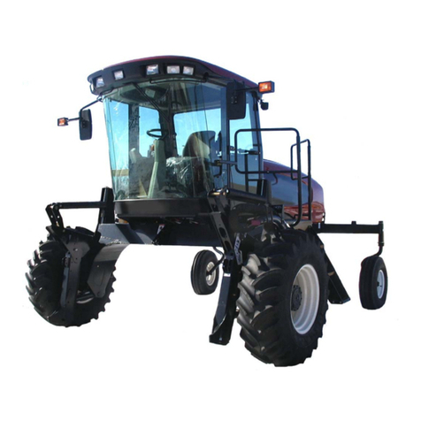
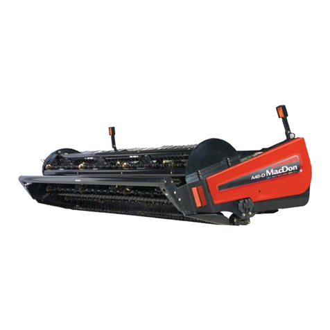
MacDon A40-D User manual

A40D and A40DX
Auger Header
Unloading and Assembly Instructions
262335 Revision A
Original Instruction
The Harvesting Specialists.

A40D Auger Header
1009163
Published November 2023
© 2023 MacDon Industries, Ltd.
The information in this publication is based on the information available and in effect at the time of printing. MacDon
Industries, Ltd. makes no representation or warranty of any kind, whether expressed or implied, with respect to the
information in this publication. MacDon Industries, Ltd. reserves the right to make changes at any time without notice.

Introduction
This instructional manual describes the unloading, setup, and predelivery requirements for the MacDon A40D and A40DX
Auger Headers, including a Grass Seed version for both models.
Refer to the Table of Contents and follow the provided procedures in the order given.
CAREFULLY READ THE INFORMATION PROVIDED IN THIS MANUAL BEFORE ATTEMPTING TO UNLOAD, ASSEMBLE, OR USE
THE MACHINE.
Conventions
The following conventions are used in this document:
•Right and left are determined from the operator’s position. The front of the auger header faces the crop.
•Unless otherwise noted, use the standard torque values provided in this manual.
NOTE:
Keep your MacDon publications up-to-date. The most current version can be downloaded from our website
(www.macdon.com) or from our Dealer-only site (https://portal.macdon.com) (login required).
•North America: [email protected]
•Australia: [email protected]
•Brazil: [email protected]
•Europe (except Russia): [email protected]
•Russia: [email protected]
This document is currently available in English only.
262335 iRevision A

Summary of Changes
At MacDon, we’re continuously making improvements, and occasionally these improvements affect product
documentation. The following list provides an account of major changes from the previous version of this document.
Section Summary of Change Internal Use
Only
Introduction, page i Added shortage and damages email contacts. Technical
Publications
Introduction, page i Added 30 Nm torque spec to be listed two ways. Technical
Publications
1.1 Safety Alert Symbols, page 1 Added Safety Alert Symbols topic. Technical
Publications
1.4 Operational Safety, page 5 Added Operational Safety topic. Technical
Publications
1.5 Hydraulic Safety, page 6 Added Hydraulic Safety topic. Technical
Publications
3.18 Attaching A40DX Auger Header, page
77
Added topic. Technical
Publications
3.19 Connecting A40DX Auger Header
Hydraulic and Electrical Systems, page 85
Added topic. Technical
Publications
5.6.1 Checking Float –M2 Series
Windrowers, page 102
Added topic. Technical
Publications
5.6.2 Setting Float –M2 Series Windrowers,
page 103
Added topic. Technical
Publications
5.6.3 Removing and Restoring Float –M2
Series Windrowers, page 104
Added topic. Technical
Publications
5.6.4 Setting Float Options with Fixed Deck –
M2 Series Windrowers, page 105
Added topic. Technical
Publications
5.14.1 Calibrating Knife Drive, page 119 Added topic. Technical
Publications
5.14.2 Calibrating Knife Drive on
HarvestTouch™Display, page 121
Added topic. Technical
Publications
Recommended Fluids and Lubricants, page Added topic. Technical
Publications
Recommended Fluids and Lubricants, page Updated the quantity of the knife drive box lubricant
from 2.2 liters to 2.1 liters.
ECN 63317
262335 ii Revision A

262335 iii Revision A
Introduction ................................................................................................................................................i
Summary of Changes....................................................................................................................................ii
Chapter 1: Safety ........................................................................................................................................ 1
1.1 Safety Alert Symbols ...............................................................................................................................1
1.2 Signal Words .........................................................................................................................................2
1.3 General Safety .......................................................................................................................................3
1.4 Operational Safety..................................................................................................................................5
1.5 Hydraulic Safety .....................................................................................................................................6
1.6 Safety Signs ...........................................................................................................................................7
Chapter 2: Unloading the Machine............................................................................................................ 9
2.1 Unloading the Header .............................................................................................................................9
2.1.1 Unloading the Header from a Truck Flatbed........................................................................................9
Chapter 3: Assembling the Machine........................................................................................................ 11
3.1 Removing Underside Shipping Stand ........................................................................................................ 11
3.2 Installing Skid Shoes.............................................................................................................................. 12
3.3 Installing Gauge Rollers ......................................................................................................................... 13
3.4 Tilting the Header into Field Position ....................................................................................................... 15
3.5 Removing Shipping Stands ..................................................................................................................... 19
3.6 Installing Tall Crop Divider Kit ................................................................................................................. 23
3.7 Adjusting Lean Bar................................................................................................................................ 24
3.8 Installing and Adjusting Pan Extensions .................................................................................................... 25
3.9 Adjusting Transport Lights...................................................................................................................... 27
3.10 Assembling Forming Shield ................................................................................................................... 28
3.11 Installing Forming Shield ...................................................................................................................... 31
3.12 Attaching A40D Auger Headers to M Series Self-Propelled Windrowers ........................................................ 34
3.12.1 Attaching A40D Header to an M100 or M105 Windrower.................................................................. 34
3.12.2 Attaching A40D an to M150, M155, or M155E4 Windrower............................................................... 40
3.12.3 Attaching A40D Header to an M200 Windrower .............................................................................. 46
3.12.4 Attaching A40D Auger Header to an M205 Self-Propelled Windrower.................................................. 52
3.13 Modifying Hydraulics –A40D Header ..................................................................................................... 57
3.13.1 Modifying Hydraulics –M100, M105 Windrowers ............................................................................ 57
3.13.2 Modifying Hydraulics –M150, M155, M155E4 Windrowers ............................................................... 59
3.13.3 Modifying Hydraulics –M200 Windrower with Reverser Manifold ...................................................... 61
3.13.4 Modifying Hydraulics –M200 Windrower without Reverser Manifold.................................................. 62
3.13.5 Modifying Hydraulics –M205 Windrower ....................................................................................... 64
3.14 Routing Reverser Manifold Jumper Hose –M Series Windrower ................................................................. 65
3.15 Hydraulic Drive Hose Routing –M Series Windrowers ............................................................................... 67
3.15.1 Hydraulic Drive Hose Routing –A40D Header and M100, M105, and M205 Windrowers......................... 67
3.16 Attaching A40DX Auger Header to M1 and M2 Series Windrowers .............................................................. 73
TABLE OF CONTENTS


262335 iv Revision A
3.17 Hydraulic Drive Hose Routing –M1 Series Windrowers.............................................................................. 76
3.18 Attaching A40DX Auger Header ............................................................................................................. 77
3.19 Connecting A40DX Auger Header Hydraulic and Electrical Systems .............................................................. 85
3.20 Repositioning Knife Drive Box Breathers ................................................................................................. 88
Chapter 4: Lubricating the Machine ........................................................................................................ 89
4.1 Greasing Procedure .............................................................................................................................. 89
4.2 Lubrication Points –Left Side of Header ................................................................................................... 90
4.3 Lubrication Points –Right Side of Header ................................................................................................. 91
4.4 Lubrication Points: Hay Conditioner ......................................................................................................... 92
4.5 Lubrication Points –Drivelines ................................................................................................................ 93
4.6 Lubrication Points: Knife and Gearbox...................................................................................................... 94
Chapter 5: Performing Predelivery Checks.............................................................................................. 95
5.1 Checking Drive Belts and Chains.............................................................................................................. 95
5.2 Checking Auger Stripper Bar Clearance..................................................................................................... 96
5.3 Checking Reel Tine to Header Pan Clearance ............................................................................................. 97
5.4 Checking and Adjusting Float –M Series Self-Propelled Windrowers.............................................................. 98
5.5 Checking and Adjusting Float –M1 and M2 Series Windrowers .................................................................... 99
5.5.1 Checking Float –M1 Series Windrowers........................................................................................... 99
5.5.2 Setting Float –M1 Series Windrowers ........................................................................................... 100
5.5.3 Removing and Restoring Float –M1 Series Windrowers.................................................................... 101
5.6 Checking and Adjusting Float –M2 Series Windrowers.............................................................................. 102
5.6.1 Checking Float –M2 Series Windrowers......................................................................................... 102
5.6.2 Setting Float –M2 Series Windrowers ........................................................................................... 103
5.6.3 Removing and Restoring Float –M2 Series Windrowers.................................................................... 104
5.6.4 Setting Float Options with Fixed Deck –M2 Series Windrowers.......................................................... 105
5.7 Leveling the Header –M Series Windrower............................................................................................. 108
5.8 Leveling Header –M1 Series Windrower ................................................................................................ 110
5.9 Leveling Header ................................................................................................................................. 112
5.10 Checking Conditioner Rolls ................................................................................................................. 114
5.11 Checking Oil Level in Conditioner Gearbox ............................................................................................ 116
5.12 Checking Optional Skid Shoes / Gauge Rollers........................................................................................ 117
5.13 Checking Lights................................................................................................................................. 118
5.14 Running up Header ........................................................................................................................... 119
5.14.1 Calibrating Knife Drive............................................................................................................... 119
5.14.2 Calibrating Knife Drive on HarvestTouch™Display........................................................................... 121
5.15 Checking Knife Speed ........................................................................................................................ 125
5.15.1 Setting Knife Speed on an M100 or M105..................................................................................... 125
Setting Knife Speed with Expansion Module (B4666)....................................................................... 126
Setting Knife Speed without Expansion Module (B4666) .................................................................. 127
5.16 Adjusting Knife and Guards................................................................................................................. 128
TABLE OF CONTENTS

262335 vRevision A
5.17 Checking Manuals............................................................................................................................. 130
Chapter 6: Reference .............................................................................................................................. 131
6.1 Torque Specifications .......................................................................................................................... 131
6.1.1 SAE Bolt Torque Specifications ..................................................................................................... 131
6.1.2 Metric Bolt Specifications ............................................................................................................ 133
6.1.3 Metric Bolt Specifications –Cast Aluminum .................................................................................... 134
6.1.4 Flare-Type Hydraulic Fittings ........................................................................................................ 135
6.1.5 O-Ring Boss Hydraulic Fittings –Adjustable .................................................................................... 136
6.1.6 O-Ring Boss Hydraulic Fittings –Non-Adjustable.............................................................................. 138
6.1.7 O-Ring Face Seal Hydraulic Fittings................................................................................................ 138
6.1.8 Tapered Pipe Thread Fittings........................................................................................................ 140
6.2 Conversion Chart................................................................................................................................ 141
6.3 Definitions ........................................................................................................................................ 142
Predelivery Checklist .............................................................................................................................. 145
Recommended Fluids and Lubricants.................................................................................................... 147
TABLE OF CONTENTS


262335 1Revision A
Chapter 1: Safety
Understanding and consistently following these safety procedures will help to ensure the safety of those operating the
machine and of bystanders.
1.1 Safety Alert Symbols
The safety alert symbol indicates important safety messages in this manual and on safety signs on the machine.
1000915
Figure 1.1: Safety Symbol
This symbol means:
•ATTENTION!
•BECOME ALERT!
•YOUR SAFETY IS INVOLVED!
Carefully read and follow the safety message accompanying this
symbol.
Why is safety important to you?
•Accidents disable and kill
•Accidents cost
•Accidents can be avoided

262335 2Revision A
1.2 Signal Words
Three signal words, DANGER,WARNING, and CAUTION, are used to alert you to hazardous situations. Two signal words,
IMPORTANT and NOTE, identify non-safety related information.
Signal words are selected using the following guidelines:
DANGER
Indicates an imminently hazardous situation that, if it is not prevented, will result in death or serious injury.
WARNING
Indicates a potentially hazardous situation that, if it is not prevented, could result in death or serious injury. It may also
be used to alert you to unsafe practices.
CAUTION
Indicates a potentially hazardous situation that, if it is not prevented, may result in minor or moderate injury. It may
also be used to alert you to unsafe practices.
IMPORTANT:
Indicates a situation that, if not prevented, could result in a malfunction or damage to the machine.
NOTE:
Provides additional information or advice.
SAFETY

262335 3Revision A
1.3 General Safety
Operating, servicing, and assembling machinery presents several safety risks. These risks can be reduced or eliminated by
following the relevant safety procedures and wearing the appropriate personal protective equipment.
1000004
Figure 1.2: Safety Equipment
CAUTION
The following general farm safety precautions should be part of
your operating procedure for all types of machinery.
Wear all protective clothing and personal safety devices that
could be necessary for the job at hand. Do NOT take chances.
You may need the following:
•Hard hat
•Protective footwear with slip-resistant soles
•Protective glasses or goggles
•Heavy gloves
•Wet weather gear
•Respirator or filter mask
1000005
Figure 1.3: Safety Equipment
In addition, take the following precautions:
•Be aware that exposure to loud noises can cause hearing
impairment. Wear suitable hearing protection devices such
as earmuffs or earplugs to help protect against loud noises.
1010391
Figure 1.4: Safety Equipment
•Provide a first aid kit in case of emergencies.
•Keep a properly maintained fire extinguisher on the
machine. Familiarize yourself with its use.
•Keep young children away from machinery at all times.
•Be aware that accidents often happen when Operators are
fatigued or in a hurry. Take time to consider the safest way
to accomplish a task. NEVER ignore the signs of fatigue.
SAFETY

262335 4Revision A
1000007
Figure 1.5: Safety around Equipment
•Wear close-fitting clothing and cover long hair. NEVER wear
dangling items such as hoodies, scarves, or bracelets.
•Keep all shields in place. NEVER alter or remove safety
equipment. Ensure that the driveline guards can rotate
independently of their shaft, and that they can telescope
freely.
•Use only service and repair parts made or approved by the
equipment manufacturer. Parts from other manufacturers
may not meet the correct strength, design, or safety
requirements.
1000008
Figure 1.6: Safety around Equipment
•Keep hands, feet, clothing, and hair away from moving
parts. NEVER attempt to clear obstructions or objects from a
machine while the engine is running.
•Do NOT modify the machine. Unauthorized modifications
may impair the functionality and/or safety of the machine. It
may also shorten the machine’s service life.
•To avoid injury or death from the unexpected startup of the
machine, ALWAYS stop the engine and remove the key from
the ignition before leaving the operator’s seat for any
reason.
1000009
Figure 1.7: Safety around Equipment
•Keep the machine service area clean and dry. Wet and/or
oily floors are slippery. Wet spots can be dangerous when
working with electrical equipment. Ensure that all electrical
outlets and tools are properly grounded.
•Keep the work area well-lit.
•Keep machinery clean. Straw and chaff on a hot engine are
fire hazards. Do NOT allow oil or grease to accumulate on
service platforms, ladders, or controls. Clean machines
before they are stored.
•NEVER use gasoline, naphtha, or any volatile material for
cleaning purposes. These materials may be toxic and/or
flammable.
•When storing machinery, cover any sharp or extending
components to prevent injury from accidental contact.
SAFETY

262335 5Revision A
1.4 Operational Safety
Follow all the safety and operational instructions given in this manual.
CAUTION
•Follow all safety and operational instructions given in your operator's manual. If you do not have a windrower
manual, get one from your Dealer and read it thoroughly.
•Never attempt to start windrower engine or operate the machine, except from the operator’s seat.
•Check the operation of all controls in a safe clear area before starting work.
•Do NOT allow riders on windrower.
•Never start or move the machine until you are sure all bystanders have cleared the area.
•Avoid travelling over loose fill, rocks, ditches or holes.
•Drive slowly through gates and doorways.
•If cutting ditch banks, use extreme caution. If the header hits an obstruction, front of the windrower will usually
swerve towards the ditch.
•When working on inclines, travel uphill or downhill when possible. Be sure to keep windrower transmission in gear
when travelling downhill.
•Never attempt to get on or off a moving windrower.
•Do NOT get off the windrower while the machine is in operation.
•To avoid bodily injury or death from unexpected startup of machine, always stop engine and remove key from
ignition before adjusting or removing plugged material from the machine.
•Operate only in daylight or good artificial light.
CAUTION
Check for excessive vibration and unusual noises. If there is any indication of trouble, shut down and inspect the
machine. Follow proper shutdown procedure as follows:
•Engage the windrower brake.
•Disengage the PTO.
•Shut down the engine, and remove the key from the ignition.
•Wait for all movement to stop.
•Dismount and engage the cylinder stops before inspecting the raised machine.
SAFETY

262335 6Revision A
1.5 Hydraulic Safety
Because hydraulic fluid is under extreme pressure, hydraulic fluid leaks can be very dangerous. Follow the proper safety
procedures when inspecting hydraulic fluid leaks and servicing hydraulic equipment.
1001205
Figure 1.8: Testing for Hydraulic Leaks
•Always place all hydraulic controls in NEUTRAL before
leaving the operator’s seat.
•Ensure that all of the components in the hydraulic system
are kept clean and in good condition.
•Replace any worn, cut, abraded, flattened, or crimped hoses
and steel lines.
•Do NOT attempt any makeshift repairs to hydraulic lines,
fittings, or hoses by using tapes, clamps, cements, or
welding. The hydraulic system operates under extremely
high pressure. Makeshift repairs can fail suddenly and create
hazardous conditions.
1001207
Figure 1.9: Hydraulic Pressure Hazard
•Wear proper hand and eye protection when searching for
high-pressure hydraulic fluid leaks. Use a piece of cardboard
as a backstop instead of your hands to isolate and identify
a leak.
•If you are injured by a concentrated, high-pressure stream
of hydraulic fluid, seek medical attention immediately.
Serious infection or a toxic reaction can develop from
hydraulic fluid piercing the skin.
1000013
Figure 1.10: Safety around Equipment
•Ensure that all components are tight and that steel lines,
hoses, and couplings are in good condition before applying
pressure to a hydraulic system.
SAFETY

262335 7Revision A
1.6 Safety Signs
Safety signs are decals placed on the machine where there is a risk of personal injury, or where the Operator should take
extra precautions before operating the controls. They are usually yellow.
1000694
Figure 1.11: Operator’s Manual Decal
•Keep safety signs clean and legible at all times.
•Replace safety signs that are missing or illegible.
•If the original part on which a safety sign was installed is
replaced, ensure that the repair part displays the current
safety sign.
SAFETY


262335 9Revision A
Chapter 2: Unloading the Machine
Follow each procedure in this chapter in order.
2.1 Unloading the Header
DANGER
To avoid injury to bystanders from being struck by machinery, do NOT allow anyone to stand in unloading area.
DANGER
Equipment used for unloading must meet or exceed the requirements specified below. Using inadequate equipment
may result in chain breakage, vehicle tipping, machine damage or bodily harm to operators or bystanders.
Table 2.1 Lifting Vehicle
Minimum capacity18000 lb. (630 kg)
Minimum fork length 1981 mm (78 in.)
IMPORTANT:
Forklifts are normally rated for a load located 610 mm (24 in.) ahead of back end of the forks. To obtain the forklift
capacity at 1220 mm (48 in.), check with your forklift distributor.
DANGER
Ensure that the forks on the forklift are secure and that no bystanders are present.
2.1.1 Unloading the Header from a Truck Flatbed
IMPORTANT:
Do NOT unload using lean bar for lifting. The chain hook slots in lean bar are only for laying the machine over into working
position after it is on the ground.
NOTE:
Take care not to bend parts on the backtube.
1. At 1220 mm (48 in.) from back end of forks.

262335 10 Revision A
To unload the header, follow these steps:
1009035
A
Figure 2.1: Forks in Position
1. Remove the hauler’s tie-down straps and chains.
2. With a forklift, approach the header from either its
underside or topside and slide forks (A) in underneath the
lifting framework as far as possible.
IMPORTANT:
When possible, approach from the underside to minimize
potential for scratching the unit.
3. Raise the header off the deck.
IMPORTANT:
If there are two headers on the flatbed, take care not to
contact the other machine while unloading.
1009165
Figure 2.2: Topside of Header in Shipping
Configuration
4. Back up until unit clears truck flatbed and slowly lower to
150 mm (6 in.) from ground.
5. Using the forklift, take the header to a designated storage
or setup area and securely set it down on the ground.
6. Repeat for the other header if required.
7. Check for shipping damage and missing parts.
UNLOADING THE MACHINE

262335 11 Revision A
Chapter 3: Assembling the Machine
Once all unloading procedures have been completed, it is time to set up the machine. Follow each procedure in this
chapter in order.
3.1 Removing Underside Shipping Stand
CAUTION
Keep feet clear when removing final bolts.
1009034
A
A
B
Figure 3.1: Underside Shipping Stand
1. Remove four bolts (A) and remove shipping stand (B).
Discard the stand and hardware.

262335 12 Revision A
3.2 Installing Skid Shoes
If the Skid Shoes kit is NOT supplied, proceed to 3.3 Installing Gauge Rollers, page 13. Otherwise, proceed as follows:
NOTE:
This kit may be installed later in the header assembly sequence, but it may be easier prior to laying the header down.
1008987
A
B
Figure 3.2: Skid Shoe Bundle
1. Unpack the skid shoe bundle.
2. Remove two clevis pins (A) from each skid shoe.
3. Remove and retain nuts, bolts, and clips (B) from skid shoe.
1005846
A
B
Figure 3.3: Skid Shoe Hardware
4. Position the skid shoe below cutterbar and insert the tabs
on skid shoe into slots (A) in frame. Secure with clevis
pin (B).
1005403
A
B
Figure 3.4: Skid Shoe Installed
5. Attach clips (A) with bolts and nuts removed earlier in this
procedure to secure the skid shoe to the cutterbar.
NOTE:
Use a socket and ratchet wrench to access the nuts.
6. Tighten the nuts.
7. Remove clevis pin (B) and adjust the skid shoe to the
desired height. Reinstall two clevis pins (B) and secure with
the lynch pins.
8. Repeat the previous steps for opposite side. Set both skid
shoes to the same position.
ASSEMBLING THE MACHINE
Other manuals for A40-D
6
This manual suits for next models
1
Table of contents
Other MacDon Farm Equipment manuals

MacDon
MacDon M155 User manual

MacDon
MacDon D65 User manual

MacDon
MacDon D1X Series User manual

MacDon
MacDon A30-D User manual

MacDon
MacDon M155E4 User manual

MacDon
MacDon D50 User manual

MacDon
MacDon A30-S User manual

MacDon
MacDon M105 User manual

MacDon
MacDon M1 Series User manual

MacDon
MacDon D1 Series User manual