MacDon D65 User manual

169603 RevisionB
Model D65
Harvest Header®
for Self-Propelled Windrowers
UNLOADING and
ASSEMBLY INSTRUCTIONS
for
NORTH AMERICAN SHIPMENTS
Published: September, 2012

169603 2Revision B
INTRODUCTION
This instructional manual describes the unloading, set-up and pre-delivery requirements for the MacDon
D65 Harvest Headers®for MacDon M Series Self-Propelled Windrowers.
Some sections apply to multipleheader configurationsand sizes.Carefully followthe instructions foryour specific
header. Use the Table of Contents to guide you to specific areas. Retain this manual for future reference.
CAREFULLY READ ALL THE MATERIAL PROVIDED BEFORE ATTEMPTING TO UNLOAD, ASSEMBLE, OR
USE THE MACHINE.
MACDON
D65 HARVEST HEADER
®

TABLE OF CONTENTS
Section/Title Page
169603 3RevisionB
INTRODUCTION........................................................................................................................................................2
GENERAL SAFETY ..................................................................................................................................................4
RECOMMENDED TORQUES ...................................................................................................................................6
A.GENERAL..........................................................................................................................................6
B.SAE BOLTS.......................................................................................................................................6
C.METRIC BOLTS................................................................................................................................6
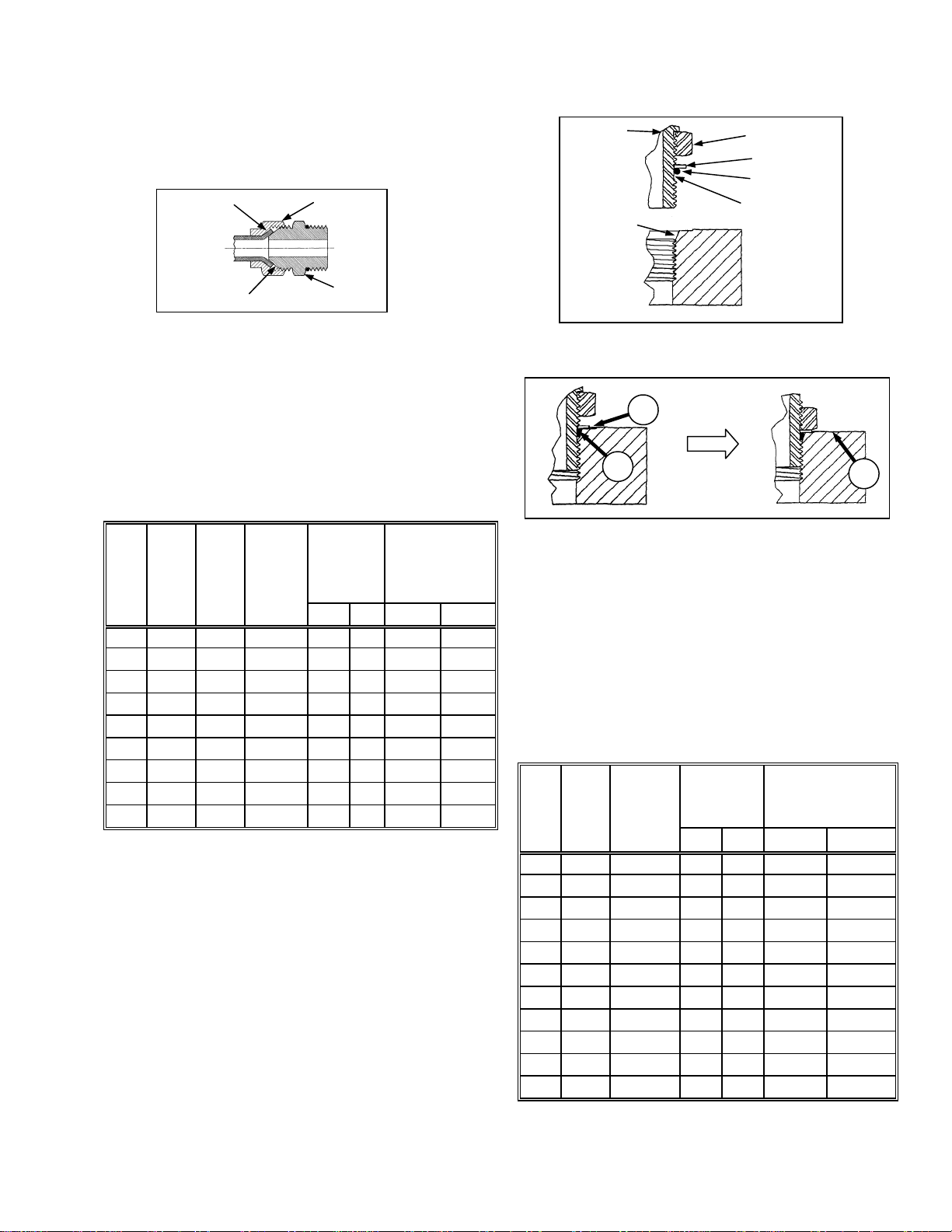
D.HYDRAULIC FITTINGS.....................................................................................................................7
CONVERSION CHART .............................................................................................................................................9
STEP 1. UNLOAD HEADER..................................................................................................................................10
STEP 2. LOWER HEADER....................................................................................................................................11
A.SINGLE REEL HEADERS...............................................................................................................11
B.DOUBLE REEL HEADERS.............................................................................................................12
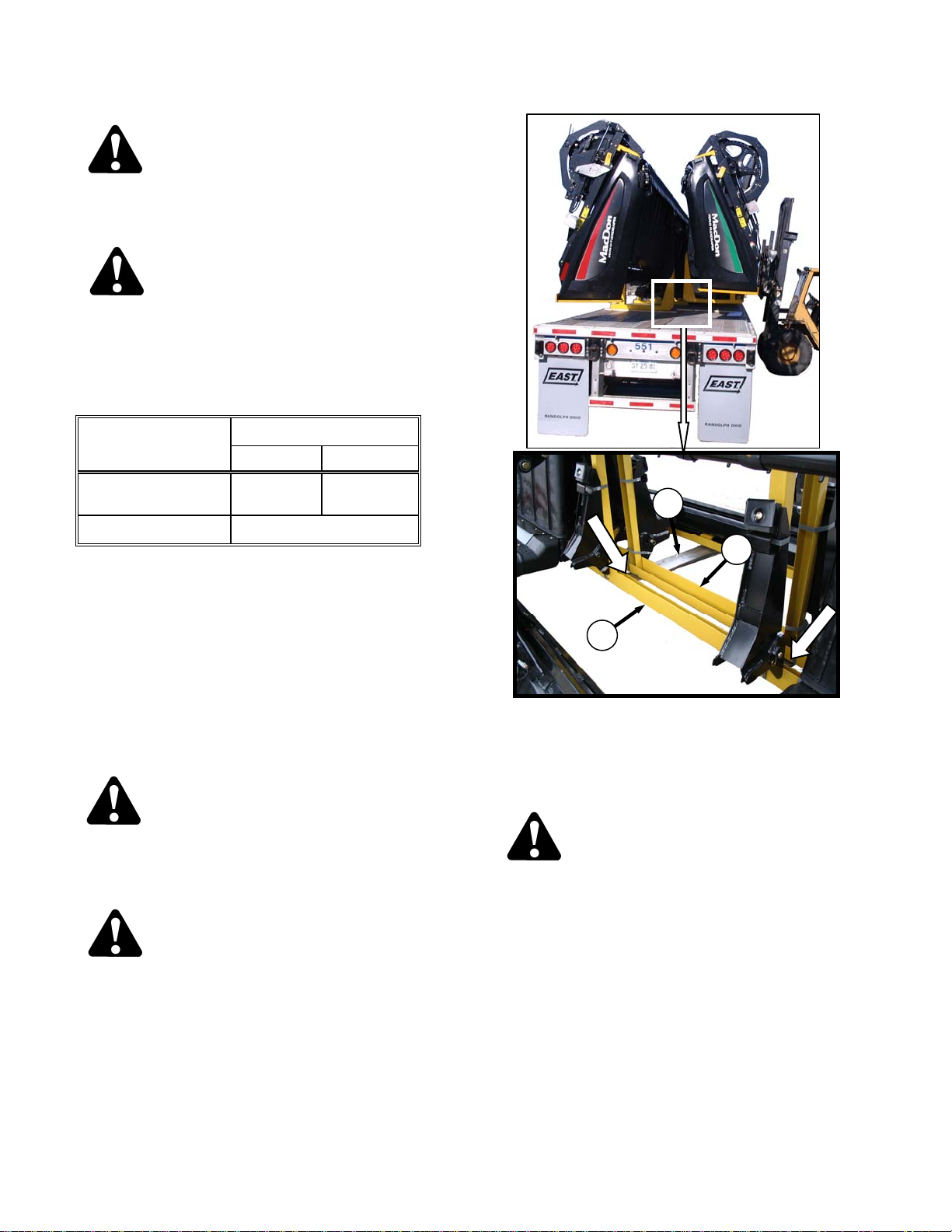
STEP 3.REMOVE SHIPPING SUPPORTS.......................................................................................................13
STEP 4.INSTALL REEL LIFT CYLINDERS .....................................................................................................15
STEP 5.ATTACH TO WINDROWER ................................................................................................................18
STEP 6.CONNECT CENTER-LINK ..................................................................................................................20
STEP 7.CONNECT HYDRAULICS...................................................................................................................22
STEP 8.ATTACH CAM ARMS..........................................................................................................................24
STEP 9.INSTALL CROP DIVIDERS.................................................................................................................25
STEP 10.TRIM DRAPER DEFLECTORS...........................................................................................................26
STEP 11.ADJUST TRANSPORT LIGHTS..........................................................................................................26
STEP 12.INSTALL OPTIONS.............................................................................................................................26
STEP 13.ADD BALLAST....................................................................................................................................27
STEP 14.PRE-DELIVERY INSPECTION............................................................................................................28
A.TIRE PRESSURE (Transport and Stabilizer Wheel Options).........................................................28
B.WHEEL BOLT TORQUE (Transport and Stabilizer Wheel Options) ..............................................28
C.SICKLE DRIVE BOX .......................................................................................................................28
D.SICKLE DRIVE BELT TENSION.....................................................................................................29
I.NON-TIMED DRIVE: SK and DK..............................................................................................29
II.TIMED DRIVE: DK....................................................................................................................29
E.REEL CENTERING.........................................................................................................................30
F.DRAPER TENSION.........................................................................................................................31
G.SKID SHOE SETTINGS..................................................................................................................32
H.HEADER LEVELLING.....................................................................................................................32
I.REEL TINE TO CUTTERBAR CLEARANCE..................................................................................33
J.DRAPER SEAL................................................................................................................................35
K.ENDSHIELDS..................................................................................................................................36
L.LUBRICATE HEADER.....................................................................................................................38
M.MANUALS .......................................................................................................................................41
STEP 16.RUN-UP THE HEADER.......................................................................................................................42
STEP 17.POST RUN-UP CHECKS.....................................................................................................................43
A.KNIFE ..............................................................................................................................................43

SAFETY
169603 4Revision B
GENERAL SAFETY
CAUTION
The following are general farm safety
precautions that should be part of your
operating procedure for all types of
machinery.
Protect yourself:
When assembling, operating and
servicing machinery, wear all the
protective clothing and personal
safety devices that COULD be
necessary for the job at hand. Don't
take chances.
You may need:
ohard hat
oprotective shoes with slip
resistant soles
oprotective glasses or goggles
oheavy gloves
owet weather gear
orespirator or filter mask
ohearing protection
Be aware that prolongedexposure
to loud noise can cause
impairment or loss of hearing.
Wearing a suitable hearing
protective device such as ear
muffs (A) or ear plugs (B) protects
against objectionable or loud
noises.
Be aware that accidents often happen
when the Operator is tired or in a
hurry to get finished. Take the time to
consider the safest way. Never ignore
warning signs of fatigue.
Provide a first-aid kit for use in case
of emergencies.
Keep a fire extinguisher on the
machine. Be sure the extinguisher is
properly maintained and be familiar
with its proper use.
Wear close-fitting
clothing and cover
long hair. Never
wear dangling items
such as scarves or
bracelets.
Keep hands, feet,
clothing and hair
away from moving parts. Never
attempt to clear obstructions or
objects from a machine while the
engine is running.
Keep all shields in place. Never alter
or remove safety equipment. Make
sure driveline guards can rotate
independently of the shaft and can
telescope freely.
(continued next page)
A B

SAFETY
169603 5Revision B
Use only service and repair parts
made or approved by the equipment
manufacturer. Substituted parts may
not meet strength, design, or safety
requirements.
Do not modify the machine.
Unauthorized modifications may
impair the function and/or safety and
affect machine life.
Stop engine, and remove key from
ignition before leaving Operator's seat
for any reason. A child or even a pet
could engage an idling machine.
Keep the area used for servicing
machinery clean and dry. Wet or oily
floors are slippery.
Wet spots can be dangerous when
working with electrical equipment. Be
sure all electrical outlets and tools are
properly grounded.
Use adequate light for the job at hand.
Keep machinery clean. Do not allow
oil or grease to accumulate on service
platforms, ladders or controls. Clean
machines before storage.
Never use gasoline, naphtha or any
volatile material for cleaning
purposes. These materials may be
toxic and/or flammable.
When storing machinery, cover sharp
or extending components to prevent
injury from accidental contact.

RECOMMENDED TORQUES
169603 6Revision B
RECOMMENDED TORQUES
A. GENERAL
The tables shown below give correct torque
values for various bolts and cap screws.
Tighten all bolts to the torques specified in
chart, unless otherwise noted throughout this
manual.
Check tightness of bolts periodically, using
bolt torque chart as a guide.
Replace hardware with the same
strength bolt.
Torque figures are valid for non-greased or
non-oiled threads and heads unless
otherwise specified. Do not grease or oil
bolts or cap screws unless specified in this
manual.
When using locking elements, increase
torque values by 5%.
B. SAE BOLTS
BOLT
DIA. "A"
(in.)
NC BOLT TORQUE*
SAE-5 SAE-8
ft·lbf N·m ft·lbf N·m
1/4 9 12 11 15
5/16 18 24 25 34
3/8 32 43 41
56
7/16 50 68 70 95
1/2 75 102 105 142
9/16 110 149 149 202
5/8 150 203 200 271
3/4 265 359 365 495
7/8 420 569 600 813
1 640 867 890 1205
* Torque categories for bolts and cap screws are identified by
their head markings.
C. METRIC BOLTS
BOLT
DIA. "A"
STD COARSE BOLT TORQUE*
8.8 10.9
ft·lbf N·m ft·lbf N·m
M3 0.4 0.5 1.3 1.8
M4 2.2 3 3.3 4.5
M5 4 6 7 9
M6 7 10 11 15
M8 18 25 26 35
M10 37 50 52 70
M12 66 90 92 125
M14 103 140 148 200
M16 166 225 229 310
M20 321 435 450 610
M24 553 750 774 1050
M30 1103 1495 1550 2100
M36 1917 2600 2710 3675
* Torque categories for bolts and cap screws are identified by
their head markings.
SAE-5 SAE-8

RECOMMENDED TORQUES
169603 7Revision B
D. HYDRAULIC FITTINGS
FLARE TYPE
a. Check flare and flare seat for defects that might
cause leakage.
b. Align tube with fitting before tightening.
c. Lubricate connection, and hand-tightenswivelnut
until snug.
d. To prevent twisting the tube(s), use two
wrenches. Place one wrench on the connector
body, and with the second, tighten the swivel nut
to the torque shown.
SAE
NO.
TUBE
SIZE
O.D.
(in.)
THD
SIZE
(in.)
NUT
SIZE
ACROSS
FLATS
(in.)
TORQUE
VALUE*
RECOMMENDED
TURNS TO
TIGHTEN
(AFTER FINGER
TIGHTENING)
ft·lbf N·m Flats Turns
3 3/16 3/8 7/16 6 8 1 1/6
4 1/4
7/16 9/16 9 12 1 1/6
5 5/16 1/2 5/8 12 16 1 1/6
6 3/8
9/16 11/16 18 24 1 1/6
8 1/2 3/4 7/8 34 46 1 1/6
10 5/8 7/8 1 46 62 1 1/6
12 3/4
1-1/16 1-1/4 75 102 3/4 1/8
14 7/8
1-3/8 1-3/8 90 122 3/4 1/8
16 1
1-5/16 1-1/2 105 142 3/4 1/8
* Torque values shown are based on lubricated connections as in
re-assembly.
O-RING TYPE
a. Inspect O-ring and seat for dirt or obvious
defects.
b. On angle fittings, back off the lock nut until
washer (A) bottoms out at top of groove (B) in
fitting.
c. Hand-tighten fitting until back-up washer (A) or
washer face (if straight fitting) bottoms on part
face (C), and O-ring is seated.
d. Position angle fittings by unscrewing no more
than one turn.
e. Tighten straight fittings to torque shown.
f. Tighten angle fittings to torque shown in the
followingtable, whileholdingbody of fitting with a
wrench.
SAE
NO.
THD
SIZE
(in.)
NUT SIZE
ACROSS
FLATS
(in.)
TORQUE
VALUE*
RECOMMENDED
TURNS TO TIGHTEN
(AFTER FINGER
TIGHTENING)
ft·lbf N·m Flats Turns
3 3/8 1/2 6 8 2 1/3
4 7/16 9/16 9 12 2 1/3
5 1/2 5/8 12 16 2 1/3
6 9/16 11/16 18 24 2 1/3
8 3/4 7/8 34 46 2 1/3
10 7/8 1 46 62 1-1/2 1/4
12 1-1/16 1-1/4 75 102 1 1/6
14 1-3/16 1-3/8 90 122 1 1/6
16 1-5/16 1-1/2 105 142 3/4 1/8
20 1-5/8 1-7/8 140 190 3/4 1/8
24 1-7/8 2-1/8 160 217 1/2 1/12
* Torque values shown are based on lubricated connections as in
re-assembly.
FLARE
FLARESEAT BODY
NUT
LOCKNUT
SEAT
WASHE
R
O-RING
GROOVE
FITTING
A
BC

RECOMMENDED TORQUES
169603 8Revision B
O-RING FACE SEAL (ORFS)
HYDRAULIC FITTINGS
* Torque values and angles shown are based on lubricated
connection, as in re-assembly.
** Always default to the torque value for evaluation of adequate
torque.
*** O-ring face seal type end not defined for this tube size.
a. Checkcomponents toensure that thesealing
surfaces and fitting threads are free of burrs,
nicks,and scratches,or anyforeign material.
b. Apply lubricant (typically Petroleum Jelly) to
O-ring and threads. If O-ring is not already
installed, installO-ring. Align thetube orhose
assembly.
c. Ensure that flat face of the mating flange
comes in full contact with O-ring.
d. Thread tube or hose nut until hand-tight. The
nut should turn freely until it is bottomed out.
Torque fitting further to the specified number
of F.F.F.T (“Flats From Finger Tight”), or to a
given torque value in the table shown in the
opposite column.
NOTE
If available, always hold the hex on the
fitting body to prevent unwanted rotation
of fitting body and hose when tightening
the fitting nut.
e. When assembling unions or two hoses
together, three wrenches will be required.
SAE
NO.
THD
SIZE
(in.)
TUB
E
O.D.
(in.)
TORQUE VALUE*
RECOMMENDED
TURNS TO
TIGHTEN (AFTER
FINGER
TIGHTENING)**
ft·lbf N·m
Tube
Nuts Swivel &
Hose
3 *** 3/16 --- --- --- ---
4 9/16 1/4 11–12 14–16 1/4–1/2 1/2–3/4
5 *** 5/16 --- --- --- ---
6 11/16 3/8 18–20 24–27
1/4–1/2
1/2–3/4
8 13/16 1/2 32–35 43–47
10 1 5/8 45–51 60–68
12 1-3/16 3/4 67–71 90–95
1/3–1/2
14 1-3/16 7/8 67–71 90–95
16 1-7/16 1 93–100 125–135
20 1-11/16 1-1/4 126–141 170–190
24 2 1-1/2 148–167 200–225
32 2-1/2 2 --- --- --- ---

CONVERSION CHART
169603 9Revision B
CONVERSION CHART
QUANTITY INCH-POUND UNITS FACTOR SI UNITS (METRIC)
UNIT NAME ABBR. UNIT NAME ABBR.
Area acres acres x 0.4047 = hectares ha
Flow US gallons per minute gpm x 3.7854 = liters per minute L/min
Force pounds force lbf x 4.4482 = Newtons N
Length inch in. x 25.4 = millimeters mm
foot ft x 0.305 = meters m
Power horsepower hp x 0.7457 = kilowatts kW
Pressure pounds per square inch psi x 6.8948 = kilopascals kPa
x .00689 = megapascals MPa
Torque
pound feet or
foot pounds lbf·ft or
ft·lbf x 1.3558 = newton meters N·m
pound inches or
inch pounds lbf·in. or
in·lbf x 0.1129 = newton meters N·m
Temperature degrees Fahrenheit ˚F (˚F - 32) x 0.56 = Celsius ˚C
Velocity
feet per minute ft/min x 0.3048 = meters per minute m/min
feet per second ft/s x 0.3048 = meters per second m/s
miles per hour mph x 1.6063 = kilometers per hour km/h
Volume
US gallons US gal. x 3.7854 = liters L
ounces oz. x 29.5735 = milliliters ml
cubic inches in.3x 16.3871 = cubic centimeters cm3or cc
Weight pounds lb x 0.4536 = kilograms kg

UNLOADING AND ASSEMBLY
169603 10 Revision B
STEP 1. UNLOAD HEADER
CAUTION
To avoid injury to bystanders from being
struck by machinery, do not allow persons to
stand in unloading area.
CAUTION
Equipment used for unloading must meet or
exceed the requirements specified below.
Using inadequate equipment may result in
chain breakage, vehicle tipping or machine
damage.
LIFTING VEHICLE HEADER SIZE
15–25 FT 30–45 FT
Minimum Capacity * 5,000 lb
(2,270 kg) 7,000 lb
(3,178 kg)
Minimum Fork Length 78 in. (1,981 mm)
* At 48 in. (1,220 mm) from back end of forks.
IMPORTANT
Forklifts are normally rated for a load
located 24 inches (610 mm) from back
end of the forks.
To obtain the forklift capacity at
48 inches (1,220 mm), check with your
forklift distributor.
a. Move trailer into position, and block trailer wheels.
b. Lower trailer storage stands.
CAUTION
Ensure that forks extend beyond the inner
support prior to lifting the header. If the forks
do not lift at the supports, damage to the
header may occur.
CAUTION
Avoid lifting the second header, and ensure
the forks do not interfere with the shipping
frame. If the forks contact the second header,
damage to the headers may occur.
c. Approach the header, and slide forks (A)
underneath shipping support (B) of header as far
as possible without contacting the shipping
support (C) of opposite header.
d. Remove hauler's tie down straps and chains.
WARNING
Be sure forks are secure before moving away
from load. Stand clear when lifting.
e. Slowly raise windrower off deck.
f. Backup untilunit clearstrailer,andslowlylowerto
6 in. (150 mm) from ground.
g. Take machine to storage or set-up area.
h. Repeat above steps for second header.
i. Check for shipping damage and missing parts.
B
C
A

UNLOADING AND ASSEMBLY
169603 11 Revision B
STEP 2. LOWER HEADER
Reposition header as follows in preparation for
assembly and set-up:
A. SINGLE REEL HEADERS
a. Choose an area with level ground.
b. Approach header from its underside, and place
forks under top of shipping frame.
c. Attach a chain at each end of frame, and secure
other end to lifting vehicle.
CAUTION
Stand clear when lowering, as machine may
swing.
d. Back up SLOWLY while lowering forks until
header is just above the ground. See illustration.
e. Place 6 in. (150 mm) blocks under each end and
center of cutterbar, and lower header onto blocks.
f. Remove chain, and move lifting vehicle to rear of
header.
g. Attach chain to center-link anchor on frame tube,
and raise rear of header so that stand can be
lowered.
h. Lower header stand bypulling pin, loweringstand,
and releasing pin to secure stand.
i. Lower header onto stand.
NOTE
If ground is soft, place a block under the
stand.
1 2
3 4

UNLOADING AND ASSEMBLY
169603 12 Revision B
B. DOUBLE REEL HEADERS
Reposition header as follows in preparation for
assembly and set-up:
a. Choose an area with level ground.
b. Drive lifting vehicle to approach header from its
underside.
IMPORTANT
Do not lift header at this location.
This procedure is only for laying the
machine over into working position.
c. Attach chain to shipping support at center
reel arm.
CAUTION
Stand clear when lowering, as machine may
swing.
d. Back up SLOWLY while lowering forks until
header is just above the ground.
e. Place 6 in. (150 mm) blocks under each end and
center of cutterbar, and lower header onto blocks.
f. Remove chain, and move lifting vehicle to rear of
header.
g. Attach chain to center-link anchor on frame tube,
and raise rear of header so that stand can be
lowered.
h. Lower header stand bypulling pin, loweringstand,
and releasing pin to secure stand.
i. Lower header onto stand.
NOTE
If ground is soft, place a block under the
stand.
2
1
3 4

UNLOADING AND ASSEMBLY
169603 13 Revision B
STEP 3. REMOVE SHIPPING
SUPPORTS
The removable supports are painted yellow.
NOTE
Unless otherwise specified, discard
supports, and all shipping material and
hardware.
a. Cut straps, and remove header boots from
shipping support. Set boots aside for later
installation.
b. Remove six bolts securing lower support to
header legs, and remove support.
c. Remove four bolts securing upper support to
header legs, and remove support.
d. Remove two bolts on each center leg shipping
support, and remove stands.
e. Ifouter legshipping supports areinstalled,remove
as follows:
1. Remove two bolts attaching stand to the leg
under the header.
2. Remove pin at top of stand, and remove
stand. (continued next page)

UNLOADING AND ASSEMBLY
169603 14 Revision B
f. Cut banding securing reel to cutterbar and
backtube (SINGLE REEL ONLY).
g. Remove reel anti-rotation brace between reel and
endsheet.

UNLOADING AND ASSEMBLY
169603 15 Revision B
STEP 4. INSTALL REEL LIFT
CYLINDERS
CAUTION
Braces On Reel Arms Keep Reel From Sliding
Forward. Do Not Remove.
a. Remove two top bolts on outboard reel arm
support—both ends.
b. Remove two top bolts on center reel arm support
(DOUBLE REEL ONLY).
c. Position sling around the reel tube close to
outboard end of reel, and attach sling to a forklift
(or equivalent).
d. Remove shipping wire/banding from cylinder, and
remove pins from lug and arm.
e. Lift reelsothat reellift cylinder mountingholes line
up with lug on endsheet and hole in reel arm.
f. Secure cylinder to endsheet and reel arm with
pins as shown. Note orientation of pins. Secure
with cotter pins.
NOTE
Cotter pin outboard at reel arm;
cotter pin inboard at endsheet.
(continued next page)
RH SHOWN - LH OPPOSITE
DOUBLE REEL ONLY

UNLOADING AND ASSEMBLY
169603 16 Revision B
NOTE
Steps g. to m. apply only to Double Reel
headers.
g. Remove sling, and reposition around reel tube
near reel center support arm.
h. Lift reel to gain access to the center lift cylinder.
i. Remove shippingwire/banding from centerreel lift
cylinder.
j. Remove socket head bolt and nut from cylinder
rod end.
k. Attach rod end of cylinder to reel arm with socket
headbolt and nut.Access hardwarethrough holes
in reel arm braces
l. Remove pin at barrel end of cylinder.
m. Adjust reel height so pin can be installed at barrel
end of cylinder and mounting structure.
n. Remove sling, and reposition around reel tube
near opposite outboard reel arm.
o. Remove shipping wire/banding from cylinder, and
remove pins from lug and arm.
p. Lift reelsothat reellift cylinder mountingholes line
up with lug on endsheet and hole in reel arm.
q. Secure cylinder to endsheet and reel arm with
pins as shown.
NOTE
Cotter pin outboard at reel arm;
Cotter pin inboard at endsheet.
(continued next page)
DOUBLE REEL
CENTER ARM - DOUBLE REEL ONLY

UNLOADING AND ASSEMBLY
169603 17 Revision B
r. Disengage center reel arm shipping support from
cutterbar, and remove.
s. Remove two bolts from reel arm supports at
endsheet, and remove support. Repeat at
other side.
t. Remove bolts and tags locking reel fore-aft
position at outer reel arms.
u. Removebolt lockingreel fore-aftposition atcenter
reel arm, and remove center reel arm shipping
channel.
v. Remove bolt lockingreel fore-aft positionat center
reel arm, and remove center reel arm shipping
channel.
DOUBLE REEL ONLY
DOUBLE REEL ONLY

UNLOADING AND ASSEMBLY
169603 18 Revision B
STEP 5. ATTACH TO
WINDROWER
IMPORTANT
To prevent damage to the lift system
when lowering header lift linkages
without a header or weight box
attachedto windrower,ensurethat float
engagement pin is installed in storage
location (A), and not installed at hole
location (B).
a. If not installed, attach draper header boots
(supplied with header) to windrower lift linkage as
follows:
DANGER
Stop engine, and remove key from ignition
before leaving Operator's seat for any reason.
A child or even a pet could engage an idling
machine.
1. Remove pin (C) from boot (D).
2. Locate boot (D) on lift linkage (E), and re-
install pin (C). Pin may be installed from either
side of boot.
3. Secure pin (C) with hairpin.
4. Repeat for opposite lift linkage.
b. Remove hairpin on pins (F),and remove pinsfrom
header legs. (continued next page)
B A
C
D
D
E
C
F

UNLOADING AND ASSEMBLY
169603 19 Revision B
CAUTION
Check to be sure all bystanders have cleared
the area.
c. Start engine, andactivate HEADERDOWNswitch
on the ground speed lever (GSL) to fully retract
header lift cylinders.
d. Slowly drive windrower forward so that boots (D)
enter header legs (G). Continue to drive slowly
forwarduntil linkages contact supportplates in the
lower header legs, and header nudges forward.
e. Check that linkages are properly engaged in
header legs, contacting support plates.
HEADER UP
HEADER DOWN
D
G

UNLOADING AND ASSEMBLY
169603 20 Revision B
STEP 6. CONNECT CENTER-
LINK
a. Proceed to appropriate section to connect the
center-link.
MECHANICAL LINK: M100, M105, M150, M155
DANGER
Stop engine, and remove key from ignition
before leaving Operator's seat for any reason.
A child or even a pet could engage an idling
machine.
1. Stop engine, and remove key.
2. Loosen nut (A), and rotate barrel (B) to adjust
length so that link lines up with header
bracket.
3. Install pin (C), and secure with cotter pin.
4. Adjust link to required length for proper
header angle by rotating barrel (B). Tighten
nut (A against barrel. A slight tap with a
hammer is sufficient.
CAUTION
Check to be sure all bystanders have cleared
the area.
5. Startengine andproceed to nextpage, stepb.
HYDRAULIC LINK WITHOUT SELF-ALIGNMENT
KIT: STANDARD FOR M200,M205; OPTIONAL FOR
M105, M150, M155
1. Stop engine, and remove key.
2. Relocate the pin at the frame linkage as
required to position the hook over the
header pin.
CAUTION
Check to be sure all bystanders have cleared
the area.
3. Start engine, and activate HEADER TILT
switches on GSL to extend or retract center-
linkcylinder,so that the hooklines-up withthe
header attachment pin.
4. Stop engine.
5. Push down on rod end of link cylinder until
hook engages pin on header, and is locked.
6. Check that center-link is locked onto header
by pulling upward on rod end of cylinder.
7. Start engine, and proceed to next page,
step b.
(continued next page)
C
B
A
HEADER TILT UP
HEADER
TILT DOWN
Other manuals for D65
7
This manual suits for next models
1
Table of contents
Other MacDon Farm Equipment manuals

MacDon
MacDon M155 User manual

MacDon
MacDon FlexDraper FD2 Series User manual

MacDon
MacDon A30-S User manual

MacDon
MacDon D50 User manual

MacDon
MacDon D65 User manual

MacDon
MacDon 625 User manual

MacDon
MacDon M155E4 User manual

MacDon
MacDon Crop Lifter User manual

MacDon
MacDon M155 User manual

MacDon
MacDon A40-D User manual

MacDon
MacDon A30-S User manual

MacDon
MacDon R216 User manual

MacDon
MacDon R116 User manual

MacDon
MacDon R85 User manual

MacDon
MacDon D50 User manual

MacDon
MacDon A30-S User manual

MacDon
MacDon M105 User manual

MacDon
MacDon D1X Series User manual

MacDon
MacDon R113 User manual

MacDon
MacDon M1 Series User manual