Makita DC24SA Manual

Models No.
Description
PRODUCT
TECHNICAL INFORMATION
CONCEPTION AND MAIN APPLICATIONS
Specification
P 1 / 8
DC24SA
Charger
This new charger allows you to charge new Ni-MH battery
from 7.2V to 24V. This charger contains trickle charging function.
Its brief benefits are listed below.
1. The charging time for new 24V Ni-MH batteries is as follows.
* B2417 / 1.7Ah : approx. 30 min.
* B2430 / 3.0Ah ; approx. 60 min.
2. Innovative computer controlled charging system realized most suitable
charge by making the digital communication between charger and battery.
3. Cooling system to keep the ideal temperature for charge.
4. Power display for battery ; It displays the charging amounts of battery
in two steps. (less than 80% or more than 80% of charge)
5. The adapter ADP01 (optional acc.) enables to charge the existing
7.2V - 24V Ni-Cd and Ni-MH batteries, too.
6. The adapter ADP02 (optional acc.) enables to refresh inactive
batteries
Continuous Rating (W)
Voltage (V) Cycle (Hz) Input Output Output Voltage (V)
120 135
135
135
Output
Current (A)
220 - 240
230 - 240
50 - 60
50 - 60
50 - 60
D/C 6.5
D/C 6.5
D/C 6.5
D/C 7.2 - 12
D/C 7.2 - 12
D/C 7.2 - 12
Charging time
New battery The existing battery
(adaptor is required)
L
W
H
Dimensions : mm ( " )
Width ( W )
Height ( H )
Length ( L )
175 (6-29/32)
110 (4-5/16)
215 (8-15/32)
Voltage ( V )
Charging
time
Ni-MH
Ni-Cd
3.0 Ah
2.6 Ah
2.2 Ah
1.7 Ah
2.0 Ah
1.3 Ah
1.7 Ah
Power display for battery
Cooling fan
Cord length : m (ft)
Net weight :Kg (lbs )
7.2 - 18 7.2 - 18
19.2 - 24
35
35
40
20
60
30
20
17
13
30
1.7 (3.7)
2.0 (6.6)
Yes
Yes
No
No
Optional accessories
* Interchangeable adapter ADP01 for the existing batteries
* Refreshing adapter ADP02

Features and benefits P 2 / 8
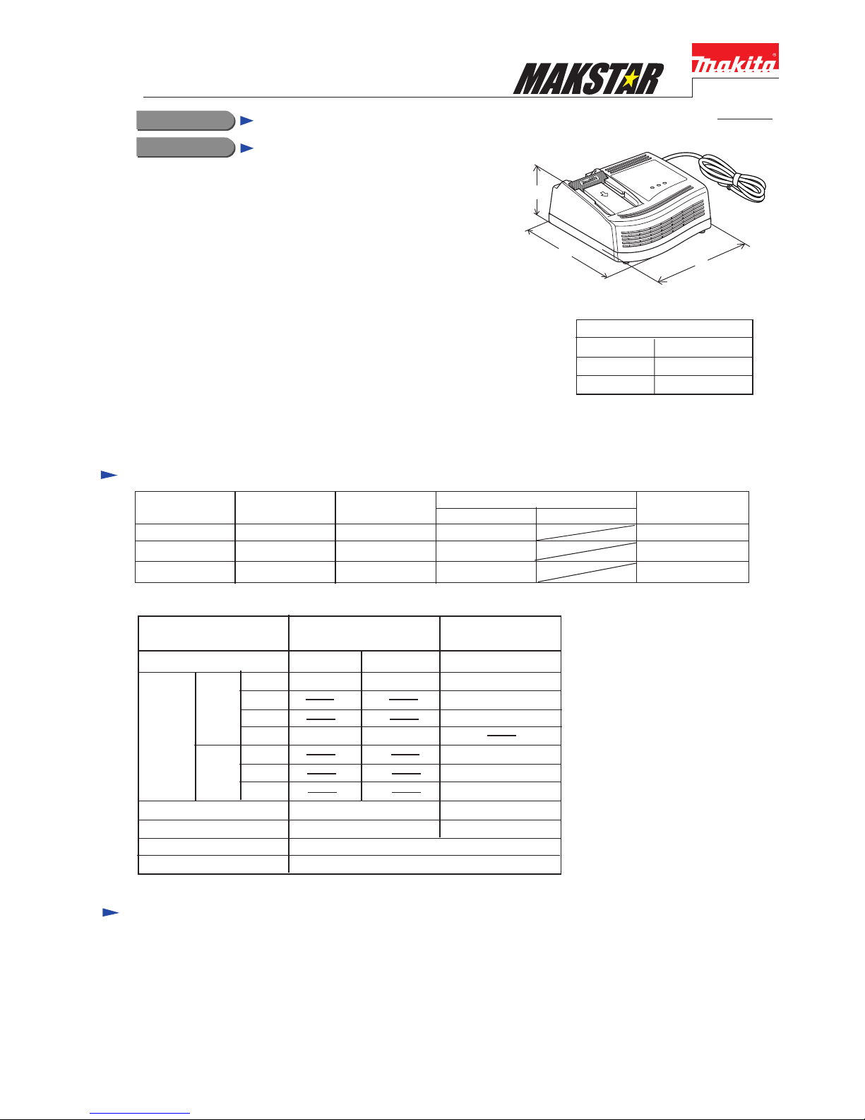
Chargeable for 7.2V - 24V
batteries
Longer life of battery
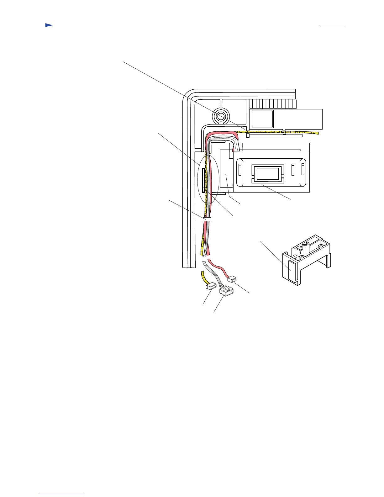
2. Cooling system
The cooling fan prevents the over heat on battery and keep the optimum temperature for charging.
3. The charging control system
This system controls the output current depending on the temperature on the battery in charging process.
The following innovative systems extend the battery's life approx.50% longer.
1. Conditioning charge
The charger receives distinctive data (temperature, history of usage ect.)
from built-in memory chip installed in battery, and decides the most suitable conditions to charge the battery.
The conditioning charge will start, when the battery is employed repeatedly under the following conditions,
which have bad influence on battery's life.
1. Charge under high room temperature (higher than 40°C)
2. Charge under low room temperature (lower than 10°C)
3. Recharge for full charged battery
4. Over discharge (continue to discharge battery in spite of machine's power down.)
Even if the cooling system does not work (because of breakdown of fan or obstruction of vent etc.),
the conditioning charge functions and starts to charge selecting the most friendly method to the battery.
Charging light indicating charging
process and charging condition
with red, green and yellow
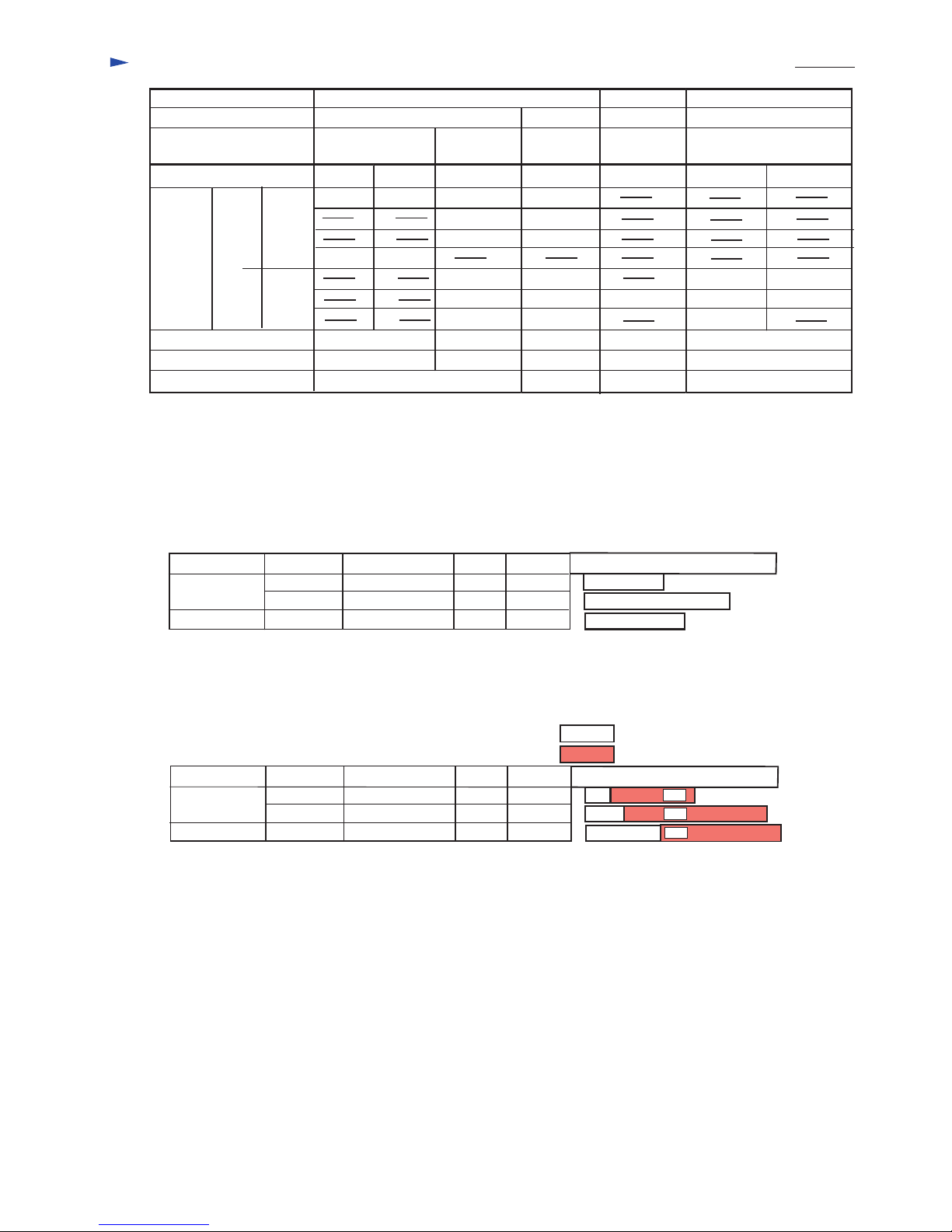
Charging light
Mark Condition
Two green lights flash, when the charger
is connected to the power source.
One red light is on, when the battery
cartridge is inserted into the charger.
Stand by to charge.
Two red lights are on.
Two green lights are on,
indicating the charged condition in 0 - 79%.
indicating the charged condition
in more than 80%.
Finish of charge.
Two red lights flash,
One red light flashes.
Red and green lights flash alternately. Impossible to charge, because
* the life of battery is over.
or
* the vent on charger or battery is clogged.
Cooling the inserted battery.
Its temperature is higher than 70°C.
The charge is stopped until the battery is cooled.
Cooling the inserted battery.
Its temperature is lower than 70°C.
The charge is stopped until the battery is cooled.
One yellow light is on
One yellow light flashes.
Conditioning charge is started.
The charging time can be longer than usual.
Breakage on cooling system
(The vent of charger or battery is clogged, or
the cooling fan is damaged.)
Charging lights

Comparison of products P 3 / 8
New battery
Voltage ( V )
Charging
time
Ni-MH
Ni-Cd
3.0 Ah
2.6 Ah
2.2 Ah
1.7 Ah
2.0 Ah
1.3 Ah
1.7 Ah
Power display for battery
Cooling fan
Net weight :Kg
7.2 - 18 7.2 - 14.4
7.2 - 18
19.2 - 24
35 min.
35 min.
40 min.
20 min.
60 min.
30 min.
20 min.
17 min.
15 min.
13 min.
30 min.
75 min.
90 min.
65 min.
50 min.
60 min.
40 min.
40 min.
1.7
Yes
Yes
No
No
No
No
No
No
No
No
Manufacturer
Model No.
*The existing
battery
*The existing battery : The interchangeable adaptor is required to charge with DC24SA.
MAKITA
DC24SA DC1801
The existing
battery
**Model B
Competitor A
Model A
**Model B : US. specifications
24 min. 24
0.48 0.59 0.9
7.2 - 18
12 min.
9 (1.2Ah)
15 min.
27 min.
Comparison of charging time
1. Testing condition A. Room temperature : 20°C
B. Battery's temperature : 20°C
2. Testing condition A. Room temperature : 20°C
B. Battery's temperature : 70°C (pull out from the just operated machine)
MAKITA
Competitor B
DC24SA
DC24SA
Manufacturer Charger Battery Type No. Voltage Capacity
B2417 (Ni-MH) 24 V 1.7 Ah
B2430 (Ni-MH) 24 V 3.0 Ah
B-1 (Ni-Cd) 24 V 1.7 Ah
Model B
Competitor B B-1 (Ni-Cd)
Model B
30
55
38
Charging time (Approx. minutes)
MAKITA DC24SA
DC24SA
Manufacturer Charger Battery Type No. Voltage Capacity
B2417 (Ni-MH) 24 V 1.7 Ah
B2430 (Ni-MH) 24 V 3.0 Ah
24 V 1.7 Ah
Time for stand by to charge
Time for charge
Charging time (Approx. minutes)
9
15
28
32
55
45
41
73<
70
< Note > The above figures about the charging time may change, which depends on the conditions of
charger, battery etc.
Competitor B

Repair P 4 / 8
<1> Reverse the charger and remove 4 tapping screws 4 x 20 after taking off cap 13. (See Fig.1.)
<2> Put the charger in the working position again, and remove charger case from circuit board complete. (See Fig. 2.)
<3> Circuit board complete can not be repaired. Because the circuit itself is molded on the board
with the urethane resin. It has to be replaced as a " circuit board complete", which we have the
following types.
* 120V Circuit board complete for low voltage area
* 220-240V Circuit board complete for high voltage area
<4> Replacement of terminal unit
Disconnect the connector CN2 and CN3 from circuit board complete, and replace the broken terminal
unit with the new one. Pay attention, not to lose compression spring 4.
Cap 13
Tapping
screw 4 x 20 Cap 13
Tapping
screw 4 x 20
Fig.1.
Charger case
Circuit board complete
Fig.2
Terminal unit
Compression spring 4
Terminal base
Connector CN2
Connector CN3
Scirocco fan
Connector CN1
Scirocco fan
Band
Fig. 3

Repair P 5 / 8
<5> Replacement of scirocco fan
Disconnect the connector CN1 from circuit board complete and replace the broken scirocco fan with the new one.
(See Fig. 4.)
<6> Replacement of terminal cover
1. Remove the old terminal cover.
2. Attach torsion spring 14 on the new terminal cover as illustrated in Fig.5..
3. Hook the torsion spring 14 to the rib of charger case from its inside as illustrated in Fig. 6.
4. Hook the boss of terminal cover to the rib of charger case as illustrated in Fig.6.
Scirocco fan
Connector CN1
Terminal base
Band
Fig. 4
Fig. 5
Hook the bosses
of terminal cover
to the rib of charger case
Terminal cover
Attach torsion spring
14 to the boss.
Hook the torsion spring 14
to the rib of charger case
Terminal cover
Fig. 6 (Bottom view of charger case)
Terminal cover
<7> Assembling terminal unit
Insert compression spring 4 into the hole
of terminal base as illustrated in Fig. 7.
Compression spring 4
Insert 3 bosses of terminal unit into the holes
of terminal base as illustrated in Fig. 7.
Terminal base
Terminal unit
Pass the lead wires of terminal unit
without slacking, along the portion marked
with .
Fig. 7

Repair P 6 / 8
<8> Assembling cord
Hold the cord with labyrinth figured lead holder as illustrated in Fig. 8.
Fig. 8
Cord has to be passed through
cord guard.
<9> In case of damaged varistor or fuse, they can be repaired according to the following procedure without
replacing the circuit board.
(1) How to find broken varistor
a. In case that the surface of varistor (ref. to the following illustration) has broken or has become black, and
fuse has been cut, the varistor has been damaged.
b. Varistor can be damaged easily, if the charger is plugged in a double voltage of the rating one.
c. It is considered that the varistor has been broken for other reasons, if the fuse is broken while the surface
of varistor is not damaged. In this case charging circuit complete has to be replaced.
Varistor
Fuse for 220 - 240V
Fuse for 120V
Fig. 9
Circiut board complete
(2)Removing broken varistor
A. Cut the lead wire of varistor at the height
of about 10mm from the surface of urethane resin.
B. Take off lead wire's sheath by 2-3mm
with nipper to expose the core.
Cut approx. by 10mm
2-3mm
(3)Assembling new Varistor (See Fig. 12)
a. Cut new varistor's lead wires to 10 mm, and insert
them about 5mm depth between the sheath
and the core.
Fig. 10
Fig. 11
b. Solder both lead wires, being so careful that they
may not contact with each other.
Approx. 10mm
Insert about 5mm depth.
Solder here.
Fig. 12

Repair P 7 / 8
(4) Replacing fuse for 220 - 240V (See Fig. 13)
1. Remove damaged fuse from the receptacle, and replace the damaged one with new fuse.
(4A) Replacing fuse for 120 (See Fig. 13A.)
1. Remove damaged fuse from terminal with soldering iron.
2. Connect the wire of fuse to the terminal by soldering.
< Note > Be careful not to overheat the fuse with soldering iron. Otherwise the wire
of fuse may be cut with the heat of soldering iron.
Fuse for 120V
Fig. 13
Fig. 13A
Receptacles
Fuse for 220 - 240V
Terminal
Cap 13
Tapping
screw 4 x 20 Cap 13
Tapping
screw 4 x 20
<9> When finish of repair, fasten circuit board complete to charger case
with 4 tapping screws 4 x 20.
And, do not forget to attach 4 caps 13.
Fig. 14

Wiring diagram P 8 / 8
Set lead wire of circa fan
in the lead holder.
Bind the lead wires
with band.
Secure the connection of
connector CN1, CN2 and CN3
to circuit board complete.
Scirocco fan
Terminal unit
Lead holder of terminal
base where the lead wires
are passed.
Terminal base
Pass lead wires of terminal unit and
scirocco fan through the lead holder
equipped on the terminal base.
Connector CN1
Connector CN2
Connector CN3
Other manuals for DC24SA
2
Table of contents
Other Makita Batteries Charger manuals

Makita
Makita DC64WA User manual

Makita
Makita DC18RD User manual

Makita
Makita DC24SC Manual

Makita
Makita DC1850 Manual

Makita
Makita MAKSTAR DC18RA User manual

Makita
Makita MAKSTAR DC18RA User manual

Makita
Makita DC36RA User manual

Makita
Makita DC1414 (MJ) User manual

Makita
Makita DC18RE User manual

Makita
Makita DC07SA User manual

Makita
Makita DC10WA Operating and maintenance manual

Makita
Makita Maktec DC1851 Guide

Makita
Makita DC1414 (MJ) User manual

Makita
Makita DC1414 (MJ) User manual

Makita
Makita DC9711 Manual

Makita
Makita MAKSTAR DC18RA User manual

Makita
Makita DC18SE User manual

Makita
Makita DC64WA User manual

Makita
Makita DC36RA Manual

Makita
Makita DC24SC User manual