Makita DHR280 User manual

DHR280
DHR281
DHR282
DHR283
EN Cordless Combination
Hammer INSTRUCTION MANUAL 10
FR Marteau Combiné sans Fil MANUEL D’INSTRUCTIONS 24
DE Akku-Kombi-Bohrhammer BETRIEBSANLEITUNG 40
IT Tassellatore combinato a
batteria ISTRUZIONI PER L’USO 56
NL Accucombihamer GEBRUIKSAANWIJZING 73
ES Martillo Rotativo Combinado
Inalámbrico
MANUAL DE
INSTRUCCIONES 90
PT Martelete Combinado A
Bateria MANUAL DE INSTRUÇÕES 107
DA Akku-kombinationshammer BRUGSANVISNING 122
EL
137
TR
Matkap KULLANMA KILAVUZU 154

2
3
2
1
Fig.1
1
2
Fig.2
1
Fig.3
1
Fig.4
1
Fig.5
1
AB
Fig.6
1 2
3
Fig.7
1 2
3
4
Fig.8

3
1
2
Fig.9
1
Fig.10
1
Fig.11
1
Fig.12
1 2
Fig.13
1
Fig.14
A
1
Fig.15

4
1
Fig.16
1
Fig.17
1
2
Fig.18
1
Fig.19
1
2
Fig.20
1
Fig.21
12
4
3
Fig.22

5
Fig.23
1
Fig.24
1
Fig.25
1
2
Fig.26
1
Fig.27
1
2
Fig.28
Fig.29

6
Fig.30
Fig.31
Fig.32
12
Fig.33
1
2
Fig.34
2
1
Fig.35
1
Fig.36
1
Fig.37

7
Fig.38
Fig.39
Fig.40
Fig.41
1
Fig.42
3
2
1
4
Fig.43
1
2
3
Fig.44

8
1
Fig.45
1 2
1 2
Fig.46
Fig.47
1
Fig.48
1 2
Fig.49
1
Fig.50

9
1
Fig.51
1 2
1 2
Fig.52
1
Fig.53
2
1
Fig.54
1
2
Fig.55
1
2
Fig.56

10 ENGLISH
ENGLISH (Original instructions)
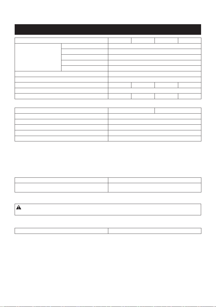
SPECIFICATIONS
Model: DHR280 DHR281 DHR282 DHR283
Capacities Concrete 28 mm
Core bit 54 mm
Diamond core bit (dry type) 65 mm
Steel 13 mm
Wood 32 mm
No load speed 0 - 980 min-1
Blows per minute 0 - 5,000 min-1
Overall length 373 mm 404 mm 373 mm 404 mm
Rated voltage D.C. 36 V
Net weight 3.8 - 4.9 kg 4.0 - 4.9 kg 3.9 - 5.0 kg 4.0 - 4.9 kg
Optional accessory
Model: DX08 (For DHR280/DHR282) DX09 (For DHR281/DHR283)
Suction performance 350 l/min
Operating stroke Up to 190 mm
Suitable drill bit Up to 260 mm
Rated voltage D.C. 18 V
Net weight 1.6 kg
without notice.
-
est combinations, according to EPTA-Procedure 01/2014, are shown in the table.
Applicable battery cartridge and charger
Battery cartridge BL1815N / BL1820B / BL1830B / BL1840B / BL1850B / BL1860B
Charger DC18RC / DC18RD / DC18RE / DC18SD / DC18SE / DC18SF /
DC18SH / DC18WC
• Some of the battery cartridges and chargers listed above may not be available depending on your region of
residence.
WARNING: Only use the battery cartridges and chargers listed above. Use of any other battery cartridges
Recommended cord connected power source
Battery adapter BAP182
• The cord connected power source(s) listed above may not be available depending on your region of residence.
• Before using the cord connected power source, read instruction and cautionary markings on them.

11 ENGLISH
Intended use
The tool is intended for hammer drilling and drilling in
brick, concrete and stone as well as for chiselling work.
It is also suitable for drilling without impact in wood,
metal, ceramic and plastic.
Noise
The typical A-weighted noise level determined accord-
ing to EN62841-2-6:
Model DHR280
Sound pressure level (LpA) : 93 dB (A)
Sound power level (LWA) : 104 dB (A)
Uncertainty (K) : 3 dB (A)
Model DHR281
Sound pressure level (LpA) : 93 dB(A)
Sound power level (LWA) : 104 dB (A)
Uncertainty (K) : 3 dB(A)
Model DHR282
Sound pressure level (LpA) : 93 dB(A)
Sound power level (LWA) : 104 dB (A)
Uncertainty (K) : 3 dB(A)
Model DHR283
Sound pressure level (LpA) : 93 dB(A)
Sound power level (LWA) : 104 dB (A)
Uncertainty (K) : 3 dB(A)
Model DHR280 with DX08
Sound pressure level (LpA) : 94 dB(A)
Sound power level (LWA) : 105 dB (A)
Uncertainty (K) : 3 dB(A)
Model DHR281 with DX09
Sound pressure level (LpA) : 93 dB(A)
Sound power level (LWA) : 104 dB (A)
Uncertainty (K) : 3 dB(A)
Model DHR282 with DX08
Sound pressure level (LpA) : 94 dB(A)
Sound power level (LWA) : 105 dB (A)
Uncertainty (K) : 3 dB(A)
Model DHR283 with DX09
Sound pressure level (LpA) : 93 dB(A)
Sound power level (LWA) : 104 dB (A)
Uncertainty (K) : 3 dB(A)
NOTE:
The declared noise emission value(s) has been
measured in accordance with a standard test method
and may be used for comparing one tool with another.
NOTE:
The declared noise emission value(s) may
also be used in a preliminary assessment of exposure.
WARNING: Wear ear protection.
WARNING: The noise emission during actual
value(s) depending on the ways in which the
tool is used especially what kind of workpiece is
processed.
WARNING: Be sure to identify safety mea-
sures to protect the operator that are based on an
estimation of exposure in the actual conditions of
use (taking account of all parts of the operating
cycle such as the times when the tool is switched
trigger time).
Vibration
The following table shows the vibration total value
(tri-axial vector sum) determined according to applica-
ble standard.
Model DHR280
Work mode Vibration
emission
Uncertainty (K)
Applicable
standard /
Test condition
Hammer
drilling into
concrete
(ah, HD)
14.5 m/s22.8 m/s2EN62841-2-6
9.7 m/s21.5 m/s2
Recommended
practical
operation*
Hammer
drilling into
concrete with
DX08 (ah, HD)
13.2 m/s22.6 m/s2EN62841-2-6
8.4 m/s22.3 m/s2
Recommended
practical
operation*
Chiselling
(ah, CHeq)
10.8 m/s21.5 m/s2EN62841-2-6
8.8 m/s21.5 m/s2
Recommended
practical
operation*
Model DHR281
Work mode Vibration
emission
Uncertainty (K)
Applicable
standard /
Test condition
Hammer
drilling into
concrete
(ah, HD)
13.3 m/s21.5 m/s2EN62841-2-6
8.9 m/s21.5 m/s2
Recommended
practical
operation*
Hammer
drilling into
concrete with
DX09 (ah, HD)
13.3 m/s21.5 m/s2EN62841-2-6
7.8 m/s21.8 m/s2
Recommended
practical
operation*
Chiselling
(ah, CHeq)
9.3 m/s22.4 m/s2EN62841-2-6
7.9 m/s21.5 m/s2
Recommended
practical
operation*
Model DHR282
Work mode Vibration
emission
Uncertainty (K)
Applicable
standard /
Test condition
Hammer
drilling into
concrete
(ah, HD)
14.5 m/s22.8 m/s2EN62841-2-6
9.7 m/s21.5 m/s2
Recommended
practical
operation*
Hammer
drilling into
concrete with
DX08 (ah, HD)
13.2 m/s22.6 m/s2EN62841-2-6
8.4 m/s22.3 m/s2
Recommended
practical
operation*
Chiselling
(ah, CHeq)
10.7 m/s21.5 m/s2EN62841-2-6
8.3 m/s21.5 m/s2
Recommended
practical
operation*

12 ENGLISH
Model DHR283
Work mode Vibration
emission
Uncertainty (K)
Applicable
standard /
Test condition
Hammer
drilling into
concrete
(ah, HD)
13.3 m/s21.5 m/s2EN62841-2-6
8.9 m/s21.5 m/s2
Recommended
practical
operation*
Hammer
drilling into
concrete with
DX09 (ah, HD)
13.3 m/s21.5 m/s2EN62841-2-6
7.8 m/s21.8 m/s2
Recommended
practical
operation*
Chiselling
(ah, CHeq)
9.3 m/s22.4 m/s2EN62841-2-6
7.5 m/s21.5 m/s2
Recommended
practical
operation*
* The test condition of recommended practical operation
meets EN 62841-2-6, except for the following points:
• Feed force is applied to the switch handle (main
• The side grip/handle (auxiliary handle) is held to
keep balance of the tool.
NOTE: The declared vibration total value(s) has been
measured in accordance with a standard test method
and may be used for comparing one tool with another.
NOTE: The declared vibration total value(s) may also
be used in a preliminary assessment of exposure.
WARNING: The vibration emission during
declared value(s) depending on the ways in which
the tool is used especially what kind of workpiece
is processed.
WARNING: Be sure to identify safety mea-
sures to protect the operator that are based on an
estimation of exposure in the actual conditions of
use (taking account of all parts of the operating
cycle such as the times when the tool is switched
trigger time).
EC Declaration of Conformity
For European countries only
The EC declaration of conformity is included as Annex A
to this instruction manual.
SAFETY WARNINGS
General power tool safety warnings
WARNING: Read all safety warnings, instruc-
with this power tool. Failure to follow all instructions
Save all warnings and instruc-
tions for future reference.
The term "power tool" in the warnings refers to your
mains-operated (corded) power tool or battery-operated
(cordless) power tool.
CORDLESS ROTARY HAMMER
SAFETY WARNINGS
Safety instructions for all operations
1. Wear ear protectors. Exposure to noise can
cause hearing loss.
2. Use auxiliary handle(s), if supplied with the
tool.
3. Hold the power tool by insulated gripping
surfaces, when performing an operation where
the cutting accessory may contact hidden
wiring. Cutting accessory contacting a "live"
wire may make exposed metal parts of the power
tool "live" and could give the operator an electric
shock.
Safety instructions when using long drill bits with
rotary hammers
1. Always start drilling at low speed and with the
bit tip in contact with the workpiece. At higher
speeds, the bit is likely to bend if allowed to rotate
freely without contacting the workpiece, resulting
2. Apply pressure only in direct line with the bit
and do not apply excessive pressure. Bits can
bend, causing breakage or loss of control, result-
Additional safety warnings
1. Wear a hard hat (safety helmet), safety glasses
and/or face shield. Ordinary eye or sun glasses
are NOT safety glasses. It is also highly recom-
mended that you wear a dust mask and thickly
padded gloves.
2.
Be sure the bit is secured in place before operation.
3. Under normal operation, the tool is designed
to produce vibration. The screws can come
loose easily, causing a breakdown or accident.
Check tightness of screws carefully before
operation.
4. In cold weather or when the tool has not been
used for a long time, let the tool warm up for
a while by operating it under no load. This
will loosen up the lubrication. Without proper
5.
sure no one is below when using the tool in
high locations.
6.
7. Keep hands away from moving parts.
8. Do not leave the tool running. Operate the tool
only when hand-held.
9. Do not point the tool at any one in the area
injure someone seriously.
10. Do not touch the bit, parts close to the bit, or
workpiece immediately after operation; they
may be extremely hot and could burn your
skin.

13 ENGLISH
11. Some material contains chemicals which may
be toxic. Take caution to prevent dust inhala-
tion and skin contact. Follow material supplier
safety data.
12.
the battery cartridge and the bit are removed
before handing the tool to other person.
13. Before operation, make sure that there is no
buried object such as electric pipe, water pipe
or gas pipe in the working area. Otherwise, the
drill bit/chisel may touch them, resulting an electric
shock, electrical leakage or gas leak.
14. Do not operate the tool at no-load
unnecessarily.
SAVE THESE INSTRUCTIONS.
WARNING: DO NOT let comfort or familiarity
with product (gained from repeated use) replace
strict adherence to safety rules for the subject
product. MISUSE or failure to follow the safety
rules stated in this instruction manual may cause
serious personal injury.
Important safety instructions for
battery cartridge
1. Before using battery cartridge, read all instruc-
tions and cautionary markings on (1) battery
charger, (2) battery, and (3) product using
battery.
2. Do not disassemble or tamper with the battery
cartridge.
or explosion.
3. If operating time has become excessively
shorter, stop operating immediately. It may
result in a risk of overheating, possible burns
and even an explosion.
4. If electrolyte gets into your eyes, rinse them
out with clear water and seek medical atten-
tion right away. It may result in loss of your
eyesight.
5. Do not short the battery cartridge:
(1) Do not touch the terminals with any con-
ductive material.
(2) Avoid storing battery cartridge in a con-
tainer with other metal objects such as
nails, coins, etc.
(3) Do not expose battery cartridge to water
or rain.
A battery short can cause a large current
breakdown.
6. Do not store and use the tool and battery car-
tridge in locations where the temperature may
reach or exceed 50 °C (122 °F).
7. Do not incinerate the battery cartridge even if
it is severely damaged or is completely worn
8. Do not nail, cut, crush, throw, drop the battery
cartridge, or hit against a hard object to the
battery cartridge. Such conduct may result in a
9. Do not use a damaged battery.
10.
The contained lithium-ion batteries are subject to
the Dangerous Goods Legislation requirements.
For commercial transports e.g. by third parties,
forwarding agents, special requirement on pack-
aging and labeling must be observed.
For preparation of the item being shipped, consult-
ing an expert for hazardous material is required.
Please also observe possibly more detailed
national regulations.
battery in such a manner that it cannot move
around in the packaging.
11. When disposing the battery cartridge, remove
it from the tool and dispose of it in a safe
place. Follow your local regulations relating to
disposal of battery.
12. Use the batteries only with the products
Installing the batteries to
-
sive heat, explosion, or leak of electrolyte.
13. If the tool is not used for a long period of time,
the battery must be removed from the tool.
14. During and after use, the battery cartridge may
take on heat which can cause burns or low
temperature burns. Pay attention to the han-
dling of hot battery cartridges.
15. Do not touch the terminal of the tool imme-
diately after use as it may get hot enough to
cause burns.
16. Do not allow chips, dust, or soil stuck into the
terminals, holes, and grooves of the battery
cartridge.
burst and malfunction of the tool or battery car-
17. Unless the tool supports the use near
high-voltage electrical power lines, do not use
the battery cartridge near high-voltage electri-
cal power lines. It may result in a malfunction or
breakdown of the tool or battery cartridge.
18. Keep the battery away from children.
SAVE THESE INSTRUCTIONS.
CAUTION: Only use genuine Makita batteries.
Use of non-genuine Makita batteries, or batteries that
have been altered, may result in the battery bursting
also void the Makita warranty for the Makita tool and
charger.
Tips for maintaining maximum
battery life
1. Charge the battery cartridge before completely
discharged. Always stop tool operation and
charge the battery cartridge when you notice
less tool power.
2.
Never recharge a fully charged battery cartridge.
Overcharging shortens the battery service life.
3.
Charge the battery cartridge with room tempera-
ture at 10 °C - 40 °C (50 °F - 104 °F). Let a hot
battery cartridge cool down before charging it.
4. When not using the battery cartridge, remove
it from the tool or the charger.
5. Charge the battery cartridge if you do not use
it for a long period (more than six months).

14 ENGLISH
Important safety instructions for
wireless unit
1. Do not disassemble or tamper with the wire-
less unit.
2. Keep the wireless unit away from young chil-
dren. If accidentally swallowed, seek medical
attention immediately.
3. Use the wireless unit only with Makita tools.
4. Do not expose the wireless unit to rain or wet
conditions.
5. Do not use the wireless unit in places where
the temperature exceeds 50 °C (122 °F).
6. Do not operate the wireless unit in places
where medical instruments, such as heart
pace makers are nearby.
7. Do not operate the wireless unit in places
where automated devices are nearby. If oper-
ated, automated devices may develop malfunction
or error.
8. Do not operate the wireless unit in places
under high temperature or places where
static electricity or electrical noise could be
generated.
9. The wireless unit can produce electromagnetic
user.
10. The wireless unit is an accurate instrument. Be
careful not to drop or strike the wireless unit.
11. Avoid touching the terminal of the wireless
unit with bare hands or metallic materials.
12. Always remove the battery on the product
when installing the wireless unit into it.
13. When opening the lid of the slot, avoid the
place where dust and water may come into the
slot. Always keep the inlet of the slot clean.
14. Always insert the wireless unit in the correct
direction.
15. Do not press the wireless activation button
on the wireless unit too hard and/or press the
button with an object with a sharp edge.
16. Always close the lid of the slot when
operating.
17. Do not remove the wireless unit from the slot
while the power is being supplied to the tool.
Doing so may cause a malfunction of the wireless
unit.
18. Do not remove the sticker on the wireless unit.
19. Do not put any sticker on the wireless unit.
20. Do not leave the wireless unit in a place where
static electricity or electrical noise could be
generated.
21. Do not leave the wireless unit in a place sub-
ject to high heat, such as a car sitting in the
sun.
22. Do not leave the wireless unit in a dusty or
powdery place or in a place corrosive gas
could be generated.
23. Sudden change of the temperature may bedew
the wireless unit. Do not use the wireless unit
until the dew is completely dried.
24. When cleaning the wireless unit, gently wipe
with a dry soft cloth. Do not use benzine, thin-
ner, conductive grease or the like.
25. When storing the wireless unit, keep it in the
supplied case or a static-free container.
26. Do not insert any devices other than Makita
wireless unit into the slot on the tool.
27. Do not use the tool with the lid of the slot dam-
aged. Water, dust, and dirt come into the slot may
cause malfunction.
28. Do not pull and/or twist the lid of the slot more
than necessary.
from the tool.
29. Replace the lid of the slot if it is lost or
damaged.
SAVE THESE INSTRUCTIONS.
FUNCTIONAL
DESCRIPTION
CAUTION: Always be sure that the tool is
before adjusting or checking function on the tool.
Installing or removing battery
cartridge
CAUTION:
installing or removing of the battery cartridge.
CAUTION: Hold the tool and the battery car-
cartridge. Failure to hold the tool and the battery
and result in damage to the tool and battery cartridge
Fig.1: 1. Red indicator 2. Button 3. Battery cartridge
To remove the battery cartridge, slide it from the tool
while sliding the button on the front of the cartridge.
To install the battery cartridge, align the tongue on the
battery cartridge with the groove in the housing and slip
it into place. Insert it all the way until it locks in place
with a little click. If you can see the red indicator as
CAUTION: Always install the battery cartridge
fully until the red indicator cannot be seen. If not,
you or someone around you.
CAUTION: Do not install the battery cartridge
forcibly. If the cartridge does not slide in easily, it is
not being inserted correctly.

15 ENGLISH
Indicating the remaining battery
capacity
Only for battery cartridges with the indicator
Fig.2: 1. Indicator lamps 2. Check button
Press the check button on the battery cartridge to indi-
cate the remaining battery capacity. The indicator lamps
light up for a few seconds.
Indicator lamps Remaining
capacity
Lighted Blinking
75% to 100%
50% to 75%
25% to 50%
0% to 25%
Charge the
battery.
The battery
may have
malfunctioned.
NOTE: Depending on the conditions of use and the
from the actual capacity.
NOTE:
the battery protection system works.
Tool / battery protection system
The tool is equipped with a tool/battery protection sys-
motor to extend tool and battery life. The tool will auto-
matically stop during operation if the tool or battery is
placed under one of the following conditions:
Overload protection
When the battery is operated in a manner that causes
it to draw an abnormally high current, the tool automat-
ically stops without any indication. In this situation, turn
to become overloaded. Then turn the tool on to restart.
Overheat protection
When the tool or battery is overheated, the tool stops
automatically. In this case, let the tool and battery cool
before turning the tool on again.
NOTE: When the tool is overheated, the lamp blinks.
Overdischarge protection
When the battery capacity is not enough, the tool stops
automatically. In this case, remove the battery from the
tool and charge the battery.
Switch action
WARNING: Before installing the battery car-
tridge into the tool, always check to see that the
switch trigger actuates properly and returns to
the "OFF" position when released.
Fig.3: 1. Switch trigger
To start the tool, simply pull the switch trigger. Tool
speed is increased by increasing pressure on the switch
trigger. Release the switch trigger to stop.
Speed change
Fig.4: 1.
Refer to the table below for the relationship between the number
Number Revolutions per
minute
Blows per minute
5980 5,000
4810 4,130
3640 3,260
2470 2,400
1300 1,550
CAUTION: Do not turn the adjusting dial when
the tool is running. Failure to do so may result in
the loss of control of the tool and cause an injury.
NOTICE: If the tool is operated continuously at
low speed for a long time, the motor will get over-
loaded, resulting in tool malfunction.
NOTICE: The speed adjusting dial can be turned
only as far as 5 and back to 1. Do not force it past
5 or 1, or the speed adjusting function may no
longer work.
NOTE: Soft no-load rotation function (For
DHR282/DHR283)
tool automatically reduces the speed at no-load to reduce
the vibration under no-load. Once operation starts with a
bit against concrete, blows per minute increase and reach
the numbers as shown in the table. When temperature is
have this function even with the motor rotating.
This function is not available when the dust collection
system is installed.
Lighting up the front lamp
Fig.5: 1. Lamp
CAUTION: Do not look in the light or see the
source of light directly.
Pull the switch trigger to light up the lamp. The lamp
keeps on lighting while the switch trigger is being pulled.
The lamp goes out approximately 10 seconds after
releasing the switch trigger.

16 ENGLISH
CAUTION: For DHR282/DHR283
the active feedback sensing technology or the soft
no-load rotation function is not working properly.
Ask your local Makita Service Center for repair.
NOTE:
the lamp. Be careful not to scratch the lens of lamp, or
it may lower the illumination.
NOTE: If the dust collection system is installed on the
tool, the lamp of the dust collection system lights up
instead of the lamp of the tool.
Reversing switch action
Fig.6: 1. Reversing switch lever
CAUTION: Always check the direction of
rotation before operation.
CAUTION:
Use the reversing switch only after
the tool comes to a complete stop. Changing the direc-
tion of rotation before the tool stops may damage the tool.
CAUTION:
When not operating the tool, always
set the reversing switch lever to the neutral position.
This tool has a reversing switch to change the direction of rota-
tion. Depress the reversing switch lever from the A side for clock-
wise rotation or from the B side for counterclockwise rotation.
When the reversing switch lever is in the neutral posi-
tion, the switch trigger cannot be pulled.
Changing the quick change chuck
for SDS-plus
For DHR281/DHR283
The quick change chuck for SDS-plus can be easily
exchanged for the quick change drill chuck.
Removing the quick change chuck
for SDS-plus
CAUTION: Before removing the quick change
chuck for SDS-plus, be sure to remove the bit.
Grasp the change cover of the quick change chuck for
SDS-plus and turn in the direction of the arrow until
the change cover line moves from the symbol to
the symbol. Pull forcefully in the direction of the arrow.
Fig.7: 1. Quick change chuck for SDS-plus
2. Change cover 3. Change cover line
Installing the quick change drill chuck
Check the line of the quick change drill chuck shows
the symbol. Grasp the change cover of the quick
change drill chuck and set the line to the symbol.
Place the quick change drill chuck on the spindle of the
tool. Grasp the change cover of the quick change drill
chuck and turn the change cover line to the symbol
until a click can clearly be heard.
Fig.8: 1. Quick change drill chuck 2. Spindle
3. Change cover line 4. Change cover
Selecting the action mode
NOTICE:
Do not rotate the action mode changing
knob when the tool is running. The tool will be damaged.
NOTICE: To avoid rapid wear on the mode
change mechanism, be sure that the action mode
changing knob is always positively located in one
of the three action mode positions.
Rotation with hammering
For drilling in concrete, masonry, etc., rotate the action
mode changing knob to the symbol. Use a tungsten-
carbide tipped bit (optional accessory).
Fig.9: 1. Rotation with hammering 2. Action mode
changing knob
Rotation only
For drilling in wood, metal or plastic materials, rotate the action mode
changing knob to the symbol. Use a twist drill bit or wood drill bit.
Fig.10: 1. Rotation only
Hammering only
For chipping, scaling or demolition operations, rotate
the action mode changing knob to the symbol. Use a
bull point, cold chisel, scaling chisel, etc.
Fig.11: 1. Hammering only
Hook
CAUTION: Never hook the tool at high loca-
tion or on potentially unstable surface.
Fig.12: 1. Hook
The hook is convenient for temporarily hanging the tool.
To use the hook, simply lift up hook until it snaps into
the open position. When not in use, always lower hook
until it snaps into the closed position.
Adjusting the nozzle position of the
dust collection system
Optional accessory
button, and then release the button at the desired position.
Fig.13: 1. Guide 2.
NOTE:
the nozzle forward completely by pushing up the
If a long drill bit is installed, extend the guide by pushing
up the extension button.
Fig.14: 1. Extension button
Adjusting the drilling depth of the
dust collection system
Optional accessory
while pushing it up. The distance (A) is the drilling depth.
Fig.15: 1.

17 ENGLISH
Torque limiter
NOTICE: As soon as the torque limiter actuates,
This will help pre-
vent premature wear of the tool.
NOTICE: Drill bits such as hole saw, which tend
to pinch or catch easily in the hole, are not appro-
priate for this tool. This is because they will cause
the torque limiter to actuate too frequently.
The torque limiter will actuate when a certain torque
level is reached. The motor will disengage from the
output shaft. When this happens, the drill bit will stop
turning.
Electronic function
The tool is equipped with the electronic functions for
easy operation.
• Constant speed control
The speed control function provides the constant
rotation speed regardless of load conditions.
• Active Feedback sensing Technology (For
DHR282/DHR283)
If the tool is swung at the predetermined accelera-
tion during operation, the motor is forcibly stopped
to reduce the burden on the wrist.
NOTE: This function does not work if the acceleration
does not reach the predetermined one when the tool
is swung.
NOTE: If the bit is swung at the predetermined
acceleration during chipping, scaling, or demolishing,
the motor is forcibly stopped. In this case, release
the switch trigger, and then pull the switch trigger to
restart the tool.
ASSEMBLY
CAUTION: Always be sure that the tool is
before carrying out any work on the tool.
Side grip (auxiliary handle)
CAUTION: Always use the side grip to ensure
safe operation.
CAUTION: After installing or adjusting the
secured.
To install the side grip, follow the steps below.
1. Loosen the thumb screw on the side grip.
Fig.16: 1. Thumb screw
2. Attach the side grip while pressing the thumb
-
sions on the tool barrel.
Fig.17: 1. Thumb screw
3. Tighten the thumb screw to secure the grip. The
Grease
Coat the shank end of the drill bit beforehand with a
small amount of grease (about 0.5 - 1 g).
This chuck lubrication assures smooth action and lon-
ger service life.
Installing or removing drill bit
Clean the shank end of the drill bit and apply grease
before installing the drill bit.
Fig.18: 1. Shank end 2. Grease
Insert the drill bit into the tool. Turn the drill bit and push
it in until it engages.
After installing the drill bit, always make sure that the
drill bit is securely held in place by trying to pull it out.
Fig.19: 1. Drill bit
To remove the drill bit, pull the chuck cover down all the
way and pull the drill bit out.
Fig.20: 1. Drill bit 2. Chuck cover
Chisel angle (when chipping,
scaling or demolishing)
The chisel can be secured at the desired angle. To
change the chisel angle, rotate the action mode chang-
ing knob to the O symbol. Turn the chisel to the desired
angle.
Fig.21: 1. Action mode changing knob
Rotate the action mode changing knob to the sym-
bol. Then make sure that the chisel is securely held in
place by turning it slightly.
Depth gauge
The depth gauge is convenient for drilling holes of
uniform depth.
Press and hold the lock button, and then insert the
depth gauge into the hex hole. Make sure that the
toothed side of the depth gauge faces the marking.
Fig.22: 1. Depth gauge 2. Lock button 3. Marking
4. Toothed side
release the lock button to lock the depth gauge.
NOTE: Make sure that the depth gauge does not
touch the main body of the tool when attaching it.
Installing or removing the dust
collection system
Optional accessory
To install the dust collection system, insert the tool into
the dust collection system all the way until it locks in
place with a little double click.
Fig.23
To remove the dust collection system, pull the tool while
Fig.24: 1.

18 ENGLISH
Dust cup
Optional accessory
Use the dust cup to prevent dust from falling over the
tool and on yourself when performing overhead drilling
operations. Attach the dust cup to the bit as shown in
attached to is as follows.
Model Bit diameter
Dust cup 5 6 mm - 14.5 mm
Dust cup 9 12 mm - 16 mm
Fig.25: 1. Dust cup
Dust cup set
Optional accessory
Before installing the dust cup set, remove the bit from
the tool if installed.
Install the dust cup set on the tool so that the sym-
bol on the dust cup is aligned with the groove in the tool.
Fig.26: 1. symbol 2. Groove
NOTE: If you connect a vacuum cleaner to the dust
cup set, remove the dust cap before connecting it.
Fig.27: 1. Dust cap
To remove the dust cup set, remove the bit while pulling
the chuck cover in the direction of the arrow.
Fig.28: 1. Bit 2. Chuck cover
Hold the root of dust cup and pull it out.
Fig.29
NOTE:
it with its printed side facing up so that groove on the
Fig.30
OPERATION
CAUTION: Always use the side grip (auxiliary
and switch handle during operations.
CAUTION: Always make sure that the work-
piece is secured before operation.
CAUTION: Do not pull the tool out forcibly
even the bit gets stuck. Loss of control may
cause injury.
CAUTION:
The dust collection system is
intended for drilling in concrete only. Do not use the
dust collection system for drilling in metal or wood.
CAUTION:
When using the tool with the dust
dust collection system to prevent dust inhalation.
CAUTION: Before using the dust collection
Failure to do so may cause dust inhalation.
CAUTION: The dust collection system col-
lects the generated dust at a considerable rate,
but not all dust can be collected.
NOTICE: Do not use the dust collection system
for core drilling or chiseling.
NOTICE: Do not use the dust collection system
for drilling in wet concrete or use this system
in wet environment. Failure to do so may cause
malfunction.
NOTE: If the battery cartridge is in low temperature,
the tool’s capability may not be fully obtained. In this
case, warm up the battery cartridge by using the
tool with no load for a while to fully obtain the tool’s
capability.
Fig.31
Hammer drilling operation
CAUTION: There is tremendous and sudden
twisting force exerted on the tool/drill bit at the time of
hole break-through, when the hole becomes clogged
with chips and particles, or when striking reinforcing
rods embedded in the concrete. Always use the side
both side grip and switch handle during opera-
tions. Failure to do so may result in the loss of control
Set the action mode changing knob to the symbol.
Position the drill bit at the desired location for the hole,
then pull the switch trigger. Do not force the tool. Light
pressure gives best results. Keep the tool in position
and prevent it from slipping away from the hole.
Do not apply more pressure when the hole becomes clogged with
chips or particles. Instead, run the tool at an idle, then remove the
drill bit partially from the hole. By repeating this several times, the
hole will be cleaned out and normal drilling may be resumed.
NOTE: Eccentricity in the drill bit rotation may occur
while operating the tool with no load. The tool auto-
matically centers itself during operation. This does not
Chipping/Scaling/Demolition
Set the action mode changing knob to the symbol.
and apply slight pressure on the tool so that the tool will
not bounce around, uncontrolled.
Pressing very hard on the tool will not increase the
Fig.32

19 ENGLISH
Drilling in wood or metal
CAUTION:
when the drill bit begins to break through the
workpiece. There is a tremendous force exerted on
the tool/drill bit at the time of hole break through.
CAUTION: A stuck drill bit can be removed
simply by setting the reversing switch to reverse
rotation in order to back out. However, the tool
CAUTION: Always secure workpieces in a
vise or similar hold-down device.
NOTICE: Never use “rotation with hammering”
when the drill chuck is installed on the tool. The
drill chuck may be damaged.
tool.
NOTICE: Pressing excessively on the tool will
not speed up the drilling. In fact, this excessive
pressure will only serve to damage the tip of your drill
bit, decrease the tool performance and shorten the
service life of the tool.
Set the action mode changing knob to the symbol.
For DHR280/DHR282
Optional accessory
Attach the chuck adapter to a keyless drill chuck to
which 1/2"-20 size screw can be installed, and then
install them to the tool. When installing it, refer to the
section “Installing or removing drill bit”.
Fig.33: 1. Keyless drill chuck 2. Chuck adapter
For DHR281/DHR283
Use the quick change drill chuck as standard equip-
ment. When installing it, refer to "changing the quick
change chuck for SDS-plus".
Hold the ring and turn the sleeve counterclockwise to
-
wise to tighten the chuck.
Fig.34: 1. Sleeve 2. Ring
To remove the bit, hold the ring and turn the sleeve
counterclockwise.
Diamond core drilling
NOTICE: If performing diamond core drilling
operations using “rotation with hammering”
action, the diamond core bit may be damaged.
When performing diamond core drilling opera-
tions, always set the action mode changing knob to
the position to use "rotation only" action.
Optional accessory
CAUTION: Do not turn the dial on the dust
case while the dust case is removed from the
dust collection system. Doing so may cause dust
inhalation.
CAUTION:
turning the dial on the dust case. Turning the dial
while the tool is running may result in the loss of
control of the tool.
the number of times to dispose of the dust.
Turn the dial on the dust case three times after col-
lecting every 50,000 mm3of dust or when you feel the
vacuum performance declined.
NOTE: 50,000 mm3of dust equivalents to drilling 10
Fig.35: 1. Dust case 2. Dial
Disposing of dust
Optional accessory
CAUTION: Always be sure that the tool is
before carrying out any work on the tool.
CAUTION: Be sure to wear dust mask when
disposing of dust.
CAUTION:
Empty the dust case regularly before
the dust case becomes full. Failure to do so may decrease
the dust collection performance and cause dust inhalation.
CAUTION: The performance of dust collection
guide. Failure to do so may cause dust inhalation.
1. Remove the dust case while pressing down the
lever of the dust case.
Fig.36: 1. Lever
2. Open the cover of the dust case.
Fig.37: 1. Cover
3.
Fig.38
NOTICE:
Blow-out bulb
Optional accessory
After drilling the hole, use the blow-out bulb to clean the
dust out of the hole.
Fig.39

20 ENGLISH
Using dust cup set
Optional accessory
Fit the dust cup set against the ceiling when operating
the tool.
Fig.40
NOTICE: Do not use the dust cup set when drill-
ing in metal or similar. It may damage the dust
cup set due to the heat produced by small metal
dust or similar.
NOTICE: Do not install or remove the dust cup
set with the drill bit installed in the tool. It may
damage the dust cup set and cause dust leak.
WIRELESS ACTIVATION
FUNCTION
Optional accessory for DHR282/DHR283
What you can do with the wireless
activation function
The wireless activation function enables clean and com-
fortable operation. By connecting a supported vacuum
cleaner to the tool, you can run the vacuum cleaner
automatically along with the switch operation of the tool.
Fig.41
To use the wireless activation function, prepare following items:
• A wireless unit (optional accessory)
• A vacuum cleaner which supports the wireless
activation function
The overview of the wireless activation function
setting is as follows. Refer to each section for detail
procedures.
1. Installing the wireless unit
2. Tool registration for the vacuum cleaner
3. Starting the wireless activation function
Installing the wireless unit
Optional accessory
CAUTION:
surface when installing the wireless unit.
NOTICE: Clean the dust and dirt on the tool
before installing the wireless unit. Dust or dirt
may cause malfunction if it comes into the slot of the
wireless unit.
NOTICE: To prevent the malfunction caused by
static, touch a static discharging material, such
as a metal part of the tool, before picking up the
wireless unit.
NOTICE: When installing the wireless unit,
always be sure that the wireless unit is inserted
in the correct direction and the lid is completely
closed.
1.
Fig.42: 1. Lid
2. Insert the wireless unit to the slot and then close
the lid.
with the recessed portions on the slot.
Fig.43: 1. Wireless unit 2.3. Lid
4. Recessed portion
When removing the wireless unit, open the lid slowly.
The hooks on the back of the lid will lift the wireless unit
as you pull up the lid.
Fig.44: 1. Wireless unit 2. Hook 3. Lid
After removing the wireless unit, keep it in the supplied
case or a static-free container.
NOTICE: Always use the hooks on the back of
the lid when removing the wireless unit. If the
hooks do not catch the wireless unit, close the lid
completely and open it slowly again.
Tool registration for the vacuum
cleaner
NOTE: A Makita vacuum cleaner supporting the
wireless activation function is required for the tool
registration.
NOTE: Finish installing the wireless unit to the tool
before starting the tool registration.
NOTE: During the tool registration, do not pull the
switch trigger or turn on the power switch on the
vacuum cleaner.
NOTE: Refer to the instruction manual of the vacuum
cleaner, too.
If you wish to activate the vacuum cleaner along with
-
tion beforehand.
1. Install the batteries to the vacuum cleaner and the
tool.
2. Set the stand-by switch on the vacuum cleaner to
"AUTO".
Fig.45: 1. Stand-by switch
3. Press the wireless activation button on the vac-
uum cleaner for 3 seconds until the wireless activation
lamp blinks in green. And then press the wireless acti-
vation button on the tool in the same way.
Fig.46: 1. Wireless activation button 2. Wireless
activation lamp
If the vacuum cleaner and the tool are linked success-
fully, the wireless activation lamps will light up in green
for 2 seconds and start blinking in blue.
NOTE:
in green after 20 seconds elapsed. Press the wireless
activation button on the tool while the wireless acti-
vation lamp on the cleaner is blinking. If the wireless
activation lamp does not blink in green, push the wire-
NOTE: When performing two or more tool registra-
-
tion one by one.
Other manuals for DHR280
11
This manual suits for next models
7
Table of contents
Languages:
Other Makita Power Tools manuals

Makita
Makita DHR263 User manual

Makita
Makita JV0600 User manual

Makita
Makita HR007G User manual

Makita
Makita HK1820L User manual

Makita
Makita 4322 User manual

Makita
Makita TW001G User manual

Makita
Makita 5621RD User manual

Makita
Makita DJV142 User manual

Makita
Makita DHG180 User manual

Makita
Makita BSR730 User manual

Makita
Makita DTR180 User manual

Makita
Makita HR2475 User manual

Makita
Makita DTW450 User manual

Makita
Makita DHS680 User manual

Makita
Makita AN634H User manual

Makita
Makita DHR281 User manual

Makita
Makita JS1300 User manual

Makita
Makita RP0900 User manual

Makita
Makita 9820-2 User manual

Makita
Makita BJN160 User manual