7
FUNCTIONAL DESCRIPTION
CAUTION:
• Always be sure that the tool is switched off and
unplugged before adjusting or checking function on the
tool.
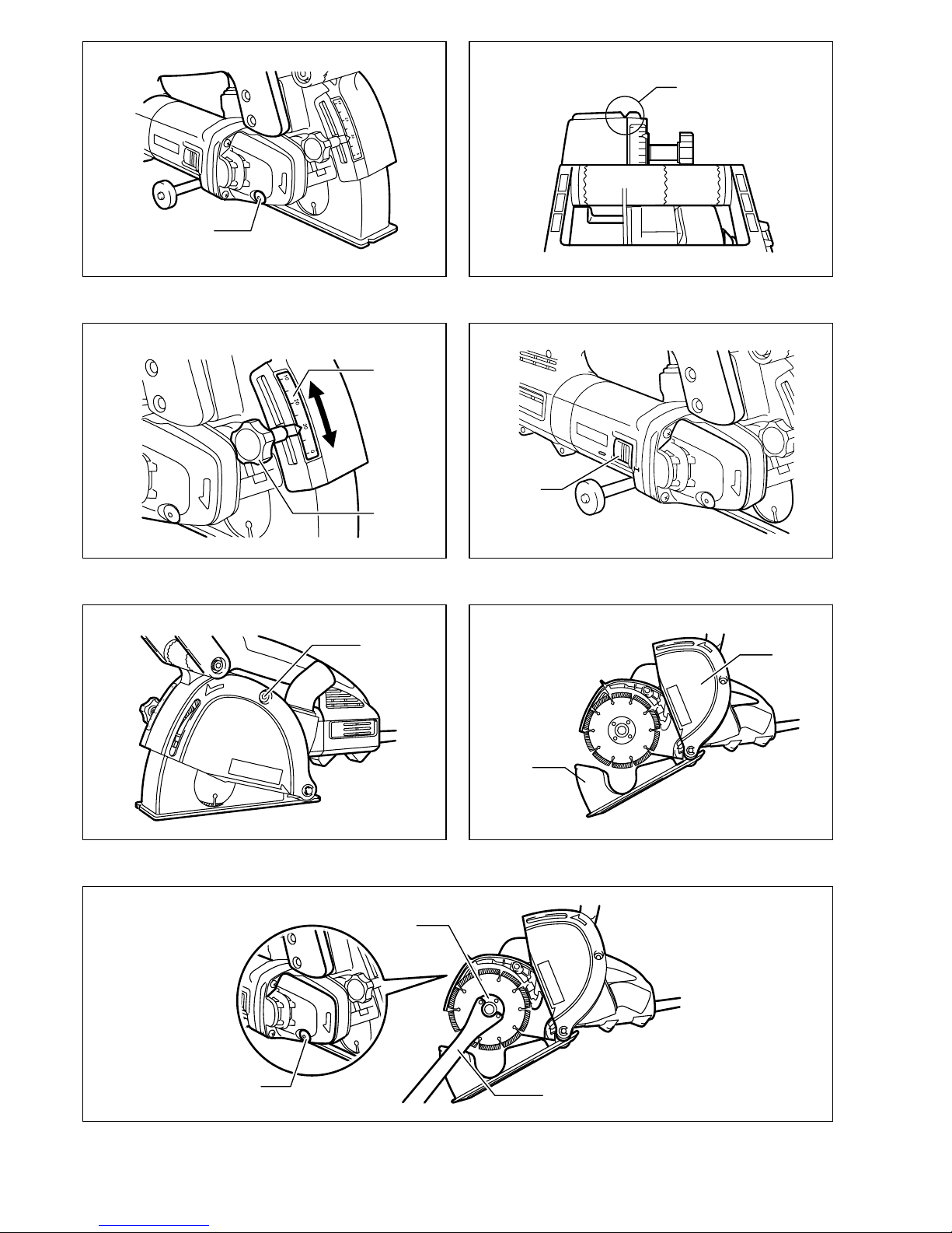
Shaft lock (Fig. 1)
CAUTION:
• Never actuate the shaft lock when the spindle is mov-
ing. The tool may be damaged.
Press the shaft lock to prevent spindle rotation when
installing or removing accessories.
Sighting (Fig. 2)
There are notches on the front and rear of the base. This
is helpful for an operator to follow a straight cutting line.
Adjusting the grooving or cutting depth (Fig. 3)
The depth of grooving or cutting can be adjusted in the
range of 0 through 30 mm.
Loosen and move the clamping screw so that the pointer
points to your desired depth graduation on the scale.
Then tighten the clamping screw firmly.
Switch action (Fig. 4)
CAUTION:
• Before plugging in the tool, always check to see that
the slide switch actuates properly and returns to the
“OFF” position when the rear of the slide switch is
depressed.
To start the tool, slide the slide switch toward the “I (ON)”
position. For continuous operation, press the front of the
slide switch to lock it.
To stop the tool, press the rear of the slide switch, then
slide it toward the “O (OFF)” position.
Electronic function
The tools equipped with electronic function are easy to
operate because of the following features.
Constant speed control
Electronic speed control for obtaining constant speed.
Possible to get fine finish, because the rotating speed is
kept constant even under load condition.
Soft start
Soft-start feature minimizes start-up shock, and makes
the tool start smoothly.
Overload protector
When the tool would be employed over the admissible
load, it will stop automatically to protect the motor and
wheel. When the load will come to the admissible level
again, the tool can be started automatically.
ASSEMBLY
CAUTION:
• Always be sure that the tool is switched off and
unplugged before carrying out any work on the tool.
Installing or removing the diamond wheel
Removal (Fig. 5, 6 & 7)
Loosen and remove the bolt with the hex wrench.
Open the cover while holding the tool base with a hand
as shown in the figure.
NOTE:
• The tool base will open at a stroke by the spring force.
Rotate the diamond wheel while pressing the shaft lock
until it engages.
Remove the lock nut by rotating it counterclockwise with
the lock nut wrench.
Remove the diamond wheel and space rings.
Adjusting the groove width (the distance between
the two diamond wheels)
The width of grooving in the workpiece can be adjusted
by changing the number of the space rings as shown in
the table. (Fig. 8)
Installation (Fig. 9)
Determine the distance of the two blades according to
the table.
To install the diamond wheel, mount it carefully onto the
spindle, making sure that the direction of the arrow on
the surface of the diamond wheel matches the direction
of the arrow on the tool. Install space ring and lock nut.
Tighten the lock nut securely clockwise with the lock nut
wrench while pushing down the shaft lock.
Return the cover and the base to the original position and
tighten the bolt to secure them.
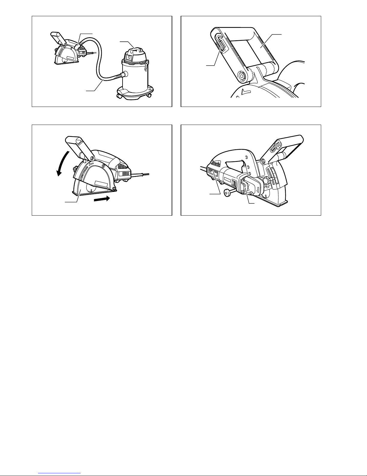
Front handle (Fig. 10 & 11)
The angle of installation of the front handle is change-
able.
To change its position, loosen the two bolts on both sides
of the front handle with the hex wrench and move the
front handle to your desired position.
NOTE:
• When the handle cannot be moved easily, loosen the
bolts furthermore.
To secure the handle, tighten the two bolts firmly.
The front handle can be shifted sideways.
To shift it, loosen and remove the two bolts on both sides
of the front handle.
Remove the cam and install it on the opposite side as
shown in the figure.
Insert the longer bolt to the hole in the handle on the side
close to the installed cam and the shorter bolt on the
opposite side.
Then tighten the two bolts firmly.
Connecting to vacuum cleaner (Fig. 12)
When you wish to perform cleaner operation, connect a
vacuum cleaner to your tool. Connect a hose of vacuum
cleaner to the dust nozzle.
NOTE:
• The dust nozzle can be rotated freely so that you can
use it at any angle according to your operation.
Hex wrench storage (Fig. 13)
When not in use, store the hex wrench as shown in the
figure to keep it from being lost.