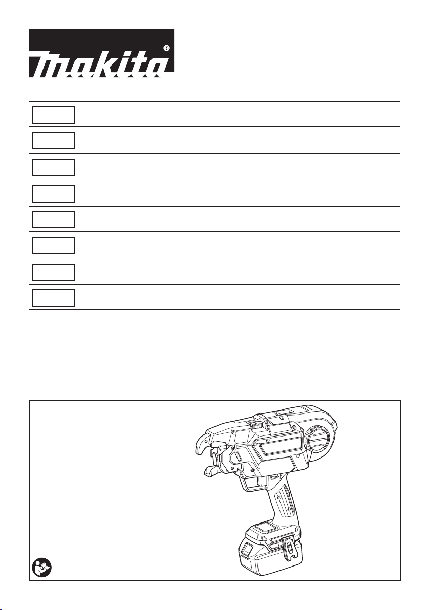
Makita DTR180 User manual

DTR180
EN Cordless Rebar Tying Tool INSTRUCTION MANUAL 11
PL Akumulatorowe Narzędzie do
Wiązania Zbrojenia INSTRUKCJA OBSŁUGI 20
HU Akkumulátoros betonacél-
kötöző szerszám HASZNÁLATI KÉZIKÖNYV 31
SK Akumulátorový nástroj na
viazanie vystužovacích tyčí NÁVOD NA OBSLUHU 41
CS Akumulátorová vázačka drátů NÁVOD K OBSLUZE 51
UK Акумуляторний Пістолет
Для В’язання Арматури ІНСТРУКЦІЯ З
ЕКСПЛУАТАЦІЇ 60
RO Mașină de legat bare pentru
armături, cu acumulator MANUAL DE INSTRUCŢIUNI 71
DE Akku-Drahtbindemaschine BETRIEBSANLEITUNG 81

1
2
3
Fig.1
1
2
Fig.2
Fig.3
1
2
Fig.4
1
2
3
Fig.5
2
1
AB
Fig.6
Fig.7
2

2
1
Fig.8
1
2
Fig.9
1
2
3
Fig.10
1
Fig.11
1
Fig.12
1
Fig.13
1
Fig.14
3

2
1
Fig.15
Fig.16
2
1
Fig.17
1
23
Fig.18
1
Fig.19
4

1
Fig.20
Fig.21
Fig.22
4
3
1
2
Fig.23
45°
45°
Fig.24
5

Fig.25
Fig.26
1
Fig.27
1
45°
45°
Fig.28
Fig.29
Fig.30
6

Fig.31
Fig.32
1
2
Fig.33
1
Fig.34
1
2
Fig.35
1
Fig.36
2
13
Fig.37
1
2
1
Fig.38
7

1
Fig.39
1
2
Fig.40
1
Fig.41
1
3
4
2
Fig.42
2
1
Fig.43
1
2
Fig.44
8

Fig.45
1
5
4
2
3
Fig.46
1
2
3
Fig.47
1
2
345
Fig.48
1
2
3
Fig.49
1
2
Fig.50
1
Fig.51
1
2
3
4
Fig.52
9

1
Fig.53
Fig.54
10

11 ENGLISH
ENGLISH (Original instructions)
SPECIFICATIONS
Model: DTR180
Tie wire (Optional accessory) ø0.8 mm
Diameter of rebars that can be tied From #3 x #3 to (#4 x 2) x (#4 x 2)
From 10 mm x 10 mm to (13 mm x 2) x (13 mm x 2)
Approximate number of ties per reel Approximately 120 ties
Overall length 304 mm
Rated voltage D.C. 14.4/18 V
Net weight 2.3 - 2.6 kg
• Duetoourcontinuingprogramofresearchanddevelopment,thespecicationshereinaresubjecttochange
without notice.
• Specicationsandbatterycartridgemaydifferfromcountrytocountry.
• Theweightmaydifferdependingontheattachment(s),includingthebatterycartridge.Thelightestandheavi-
estcombinations,accordingtoEPTA-Procedure01/2014,areshowninthetable.
Applicable battery cartridge and charger
Battery cartridge D.C.14.4 V Model BL1415N / BL1430 / BL1430B / BL1440 / BL1450 / BL1460B
D.C.18 V Model BL1815N / BL1820 / BL1820B / BL1830 / BL1830B / BL1840 /
BL1840B / BL1850 / BL1850B / BL1860B
Charger DC18RC/DC18RD/DC18RE/DC18SD/DC18SE/DC18SF/
DC18SH
•
Someofthebatterycartridgesandchargerslistedabovemaynotbeavailabledependingonyourregionofresidence.
WARNING: Only use the battery cartridges and chargers listed above. Use of any other battery cartridges
andchargersmaycauseinjuryand/orre.
Combination of rebars that can be tied
Combination of 2 rebars
#3 (10 mm) #4 (13 mm) #5 (16 mm)
#3 (10 mm)
#4 (13 mm)
#5 (16 mm)
Combination of 3 rebars
#3 x #3 (10 mm x 10 mm) #4 x #4 (13 mm x 13 mm)
#3 (10 mm)
#4 (13 mm)
#5 (16 mm) -
Combination of 4 rebars
#3 x #3 (10 mm x 10 mm) #4 x #4 (13 mm x 13 mm)
#3 x #3 (10 mm x 10 mm)
#4 x #4 (13 mm x 13 mm)
NOTICE:Ifthereisagapbetweenrebarsorifthetoolisusedatanincorrectorientation,therebarsmaynotbe
able to be tied.

12 ENGLISH
Symbols
The followings show the symbols used for the equip-
ment. Be sure that you understand their meaning before
use.
Read instruction manual.
Wear safety glasses.
Do not expose to rain.
Keep hands away from the wire reel or wire
when operating the tool.
Keep hands away from the tool tip.
Ni-MH
Li-ion
OnlyforEUcountries
Do not dispose of electric equipment or
battery pack together with household waste
material!
InobservanceoftheEuropeanDirectives,
onWasteElectricandElectronic
EquipmentandBatteriesandAccumulators
and Waste Batteries and Accumulators
and their implementation in accordance
withnationallaws,electricequipmentand
batteries and battery pack(s) that have
reached the end of their life must be col-
lected separately and returned to an envi-
ronmentally compatible recycling facility.
Intended use
The tool is intended for tying rebars.
Noise
The typical A-weighted noise level determined accord-
ingtoEN60745-2-18(EN12549):
Soundpressurelevel(LpA):78dB(A)
Uncertainty(K):3dB(A)
The noise level under working may exceed 80 dB (A).
NOTE: The declared noise emission value(s) has
been measured in accordance with a standard test
method and may be used for comparing one tool with
another.
NOTE: The declared noise emission value(s)
may also be used in a preliminary assessment of
exposure.
WARNING: Wear ear protection.
WARNING:
The noise emission during actual
use of the power tool can differ from the declared
value(s) depending on the ways in which the tool is
used especially what kind of workpiece is processed.
WARNING:
Be sure to identify safety measures
to protect the operator that are based on an estima-
tion of exposure in the actual conditions of use (tak-
ing account of all parts of the operating cycle such
as the times when the tool is switched off and when
it is running idle in addition to the trigger time).
Vibration
The vibration total value (tri-axial vector sum) deter-
minedaccordingtoEN60745-2-18(ISO8662-11):
Workmode:Tyingmetalrod
Vibration emission (ah):2.5m/s2or less
Uncertainty(K):1.5m/s2
NOTE: The declared vibration total value(s) has been
measured in accordance with a standard test method
and may be used for comparing one tool with another.
NOTE: The declared vibration total value(s) may also
be used in a preliminary assessment of exposure.
WARNING: The vibration emission during
actual use of the power tool can differ from the
declared value(s) depending on the ways in which
the tool is used especially what kind of workpiece
is processed.
WARNING: Be sure to identify safety mea-
sures to protect the operator that are based on an
estimation of exposure in the actual conditions of
use (taking account of all parts of the operating
cycle such as the times when the tool is switched
off and when it is running idle in addition to the
trigger time).
EC Declaration of Conformity
For European countries only
TheECdeclarationofconformityisincludedasAnnexA
to this instruction manual.
SAFETY WARNINGS
General power tool safety warnings
WARNING: Read all safety warnings, instruc-
tions, illustrations and specications provided
with this power tool. Failure to follow all instructions
listedbelowmayresultinelectricshock,reand/or
seriousinjury.
Save all warnings and instruc-
tions for future reference.
The term "power tool" in the warnings refers to your
mains-operated (corded) power tool or battery-operated
(cordless) power tool.

13 ENGLISH
Cordless rebar tying tool safety warnings
1.
Never point the tool toward a person. Never put
your hands or feet close to the tool tip. If you
accidentally operate the tool while it is touching
someone,itwillleadtoanunexpectedaccident.
2. Do not load wire while the power to the tool is
turned on.Otherwise,youmaygetcaughtinthe
wireandinjured.
3. Do not use the tool without closing the reel
cover.Otherwise,thewirereelmaycomeoffand
cause an accident.
4. Be sure to check that the diameters of rebars
to be tied are within the tool capacity before
beginning work.
5. Wear clothes that have close-tting hemlines
and sleeves. Do not work with a towel or other
object wrapped around your neck.Otherwise,
they may get caught in the rotating part and cause
an accident.
6. Be sure to inspect the following points before
using the tool.
• Check that no parts are damaged
• Check that no bolts are loose
• Check that safety devices operate
normally
7. If any abnormalities are found, stop using the
tool immediately. Do not repair the tool by
yourself. Ask your local Makita Service Center
for repairs. If the tool is used in an incomplete
state,anaccidentmayoccur.
8. When installing the battery cartridge, be sure
to lock the trigger and do not place your nger
on the trigger. Incorrect operation may cause an
accident.
9. When tying rebars, exercise care not to move
them.Ifrebarsmoveduetotying,youmaybe
injured.
10. Do not touch the wires during the wire tying
process.Otherwise,youmaygetcaughtinthe
wireandinjured.
11. Do not bring your hands close to the tying
point during the wire tying process.Otherwise,
youmaygetcaughtinthewireandinjured.
12. Hold the grip of the tool rmly during the wire
tying process.Otherwise,yourwristmaybe
twistedoryourbodymaybepulled,whichmay
resultinaninjury.
13. Do not move to the next tying point until the
current wire tying process is completed.
Otherwise,youmaybeinjured.
14. Pay attention to the end of the wire during the
wire tying process.Otherwise,yourhandmay
becaughtbytheendofthewire,andyoumaybe
injured.
15. Do not touch the contact plate during the wire
tying process. If you need to touch the contact
plate, be sure to lock the trigger, or turn the
power switch off and remove the battery car-
tridge.Otherwise,youmaybeinjured.
16. When you have completed the wire tying pro-
cess, pull the tool up vertically.Otherwise,the
armmaybecaughtonrebars,whichmaycause
an accident.
17.
Be careful not to drop, bump, or hit the tool. If a
strong impact is applied prior to the tool being
used, make sure that the tool is not damaged
or cracked, and that the safety devices operate
normally.Otherwise,anaccidentmayoccur.
18.
If any of the following phenomena occur, lock
the trigger, turn the power switch off, and
remove the battery cartridge from the tool. If the
tooloperatesincorrectly,anaccidentmayoccur.
• If an operating sound is heard as soon as
the battery cartridge is mounted.
• If overheating or abnormal smells or
noises are detected.
• When you are taking measures in
response to the error display. (Ask your
local Makita Service Center for repairs.)
• When loading or unloading a wire reel.
• When you move while holding the tool
during work.
• When you do not use the tool.
• When you inspect or adjust the tool.
• When you remove a stranded wire.
19. When working on scaffolding, always stabilize
it and work using a posture that will ensure
you maintain your balance. If scaffolding is
unstable,anaccidentmayoccur.
20. When working on a roof or similar locations,
move in a forward direction while working so
that you can see where you are going. If you
moveinabackwarddirectionwhileworking,you
may lose your footing and cause an accident.
21.
If you are working in a highly elevated location,
ensure that no one is below you, and pay atten-
tion to ensure you do not drop any tools while
working. Dropping the tool may cause an accident.
22. Do not use the tool for any work other than
wire tying.Otherwise,anaccidentmayoccur.
23.
Always use Makita's genuine wires. If wires are not
used for a long period of time, they may rust. Do not
use rusted wires.Otherwise,theymaycauseanaccident.
24. After tying, check for wire breakage due to
excessive twisting. If any wires are broken,
tying strength will be lost. Adjust the tying
strength, and tie the rebars again.
25. Securely place the arm against the rebars. If
itisnotsecurelypositioned,aclearancewillbe
createdbetweentherebars,andtyingstrengthwill
be compromised.
Important safety instructions for
battery cartridge
1.
Before using battery cartridge, read all instruc-
tions and cautionary markings on (1) battery char-
ger, (2) battery, and (3) product using battery.
2. Do not disassemble battery cartridge.
3. If operating time has become excessively
shorter, stop operating immediately. It may
result in a risk of overheating, possible burns
and even an explosion.
4. If electrolyte gets into your eyes, rinse them
out with clear water and seek medical atten-
tion right away. It may result in loss of your
eyesight.

14 ENGLISH
5. Do not short the battery cartridge:
(1) Do not touch the terminals with any con-
ductive material.
(2) Avoid storing battery cartridge in a con-
tainer with other metal objects such as
nails, coins, etc.
(3) Do not expose battery cartridge to water
or rain.
A battery short can cause a large current
ow, overheating, possible burns and even a
breakdown.
6. Do not store the tool and battery cartridge in
locations where the temperature may reach or
exceed 50 °C (122 °F).
7. Do not incinerate the battery cartridge even if
it is severely damaged or is completely worn
out. The battery cartridge can explode in a re.
8. Be careful not to drop or strike battery.
9. Do not use a damaged battery.
10.
The contained lithium-ion batteries are subject to
the Dangerous Goods Legislation requirements.
Forcommercialtransportse.g.bythirdparties,
forwardingagents,specialrequirementonpack-
aging and labeling must be observed.
Forpreparationoftheitembeingshipped,consult-
ing an expert for hazardous material is required.
Pleasealsoobservepossiblymoredetailed
national regulations.
Tape or mask off open contacts and pack up the
battery in such a manner that it cannot move
around in the packaging.
11. When disposing the battery cartridge, remove
it from the tool and dispose of it in a safe
place. Follow your local regulations relating to
disposal of battery.
12. Use the batteries only with the products
specied by Makita. Installing the batteries to
non-compliantproductsmayresultinare,exces-
siveheat,explosion,orleakofelectrolyte.
13. If the tool is not used for a long period of time,
the battery must be removed from the tool.
SAVE THESE INSTRUCTIONS.
CAUTION: Only use genuine Makita batteries.
Useofnon-genuineMakitabatteries,orbatteriesthat
havebeenaltered,mayresultinthebatterybursting
causingres,personalinjuryanddamage.Itwill
also void the Makita warranty for the Makita tool and
charger.
Tips for maintaining maximum
battery life
1. Charge the battery cartridge before completely
discharged. Always stop tool operation and
charge the battery cartridge when you notice
less tool power.
2.
Never recharge a fully charged battery cartridge.
Overcharging shortens the battery service life.
3.
Charge the battery cartridge with room tempera-
ture at 10 °C - 40 °C (50 °F - 104 °F). Let a hot
battery cartridge cool down before charging it.
4. Charge the battery cartridge if you do not use
it for a long period (more than six months).
FUNCTIONAL DESCRIPTION
CAUTION: Always be sure that the tool is
switched off and the battery cartridge is removed
before adjusting or checking function on the tool.
Installing or removing battery cartridge
CAUTION: Always switch off the tool before
installing or removing of the battery cartridge.
CAUTION: Hold the tool and the battery car-
tridge rmly when installing or removing battery
cartridge. Failure to hold the tool and the battery
cartridgermlymaycausethemtoslipoffyourhands
and result in damage to the tool and battery cartridge
andapersonalinjury.
►Fig.1: 1. Red indicator 2. Button 3. Battery cartridge
Toremovethebatterycartridge,slideitfromthetool
while sliding the button on the front of the cartridge.
Toinstallthebatterycartridge,alignthetongueonthe
battery cartridge with the groove in the housing and slip
it into place. Insert it all the way until it locks in place
with a little click. If you can see the red indicator on the
uppersideofthebutton,itisnotlockedcompletely.
CAUTION: Always install the battery cartridge
fully until the red indicator cannot be seen.Ifnot,
itmayaccidentallyfalloutofthetool,causinginjuryto
you or someone around you.
CAUTION: Do not install the battery cartridge
forcibly.Ifthecartridgedoesnotslideineasily,itis
not being inserted correctly.
Indicating the remaining battery capacity
Only for battery cartridges with the indicator
►Fig.2: 1. Indicator lamps 2. Check button
Pressthecheckbuttononthebatterycartridgetoindi-
cate the remaining battery capacity. The indicator lamps
light up for a few seconds.
Indicator lamps Remaining
capacity
Lighted Off Blinking
75%to100%
50%to75%
25%to50%
0%to25%
Charge the
battery.
The battery
may have
malfunctioned.

15 ENGLISH
NOTE: Depending on the conditions of use and the
ambienttemperature,theindicationmaydifferslightly
from the actual capacity.
Tool / battery protection system
The tool is equipped with a tool/battery protection sys-
tem. This system automatically cuts off power to the
motor to extend tool and battery life. The tool will auto-
matically stop during operation if the tool or battery is
placedunderoneofthefollowingconditions:
Overload protection
When the battery is operated in a manner that causes
ittodrawanabnormallyhighcurrent,thetoolauto-
matically stops and the corresponding error number is
displayedonthedisplaypanel.Inthissituation,turnthe
tool off and stop the application that caused the tool to
become overloaded. Then turn the tool on to restart.
Overheat protection
Whenthetoolorbatteryisoverheated,thetoolstops
automatically and the corresponding error number is
displayedonthedisplaypanel.Inthiscase,letthetool
and battery cool before turning the tool on again.
Overdischarge protection
Whenthebatterycapacityisnotenough,thetoolstops
automatically and the corresponding error number is
displayedonthedisplaypanel.Inthiscase,removethe
battery from the tool and charge the battery.
Main power switch
CAUTION: When you turn the power on, never
bring your limbs or face close to the binding or
rotating parts of the tool tip.Otherwise,youmay
beinjured.
CAUTION: When the power is turned on,
never touch the binding or rotating parts of the
tool tip.Otherwise,youmaybeinjured.
CAUTION: Before inserting the battery car-
tridge, be sure to release your ngers from the
switch trigger and lock the trigger. If you insert
the battery cartridge while the switch trigger is being
pulled,itmaycauseanaccidentifthewiretying
process is accidentally carried out.
►Fig.3
Whenyoupressthepowerbutton,thepowerturns
on and the tying mode lamp lights up. In order for the
tooltoadjustitsinitialposition,itoperatestemporarily.
Whenadjustmenthascompleted,thetoolstopsauto-
matically.Whenyoupressthepowerbuttonagain,the
power turns off and the tying mode lamp goes out.
►Fig.4: 1. Tying mode lamp 2.Powerbutton
NOTE: The tool has an auto power-off function. If the
switchtriggerisnotpulledfor10minutes,thetool
is automatically turned off to reduce battery power
consumption.
NOTE:Torestartthetool,turnthepoweronagain.
Mode switching button
When the power is turned on and the tying mode lamp
islit,youcanselectthesingleactuationmodeorthe
continuous actuation mode via the mode switching but-
ton.Whenyouturnthepoweronagain,thetoolstartsin
the mode that was most recently selected.
►Fig.5: 1. Mode switching button 2.Singleactuation
mode 3. Continuous actuation mode
Switch action
WARNING: Before installing the battery car-
tridge into the tool, always check to see that the
switch trigger actuates properly and returns to
the "OFF" position when released.
CAUTION: When not operating the tool,
depress the trigger-lock button from side to
lock the switch trigger in the OFF position.
►Fig.6: 1.Switchtrigger2. Trigger-lock button
Topreventtheswitchtriggerfromaccidentallypulled,
thetrigger-lockbuttonisprovided.Tostartthetool,
depress the trigger-lock button from A side and pull the
switch trigger. Release the switch trigger to stop. After
use,pressinthetrigger-lockbuttonfromBside.
Whenyoupulltheswitchtrigger,thetoolperformsthe
nextsequentialoperationsasfollows,andthetoolstops
automatically.
1. Feed the wire.
2. Cut the wire.
3. The hook holds and twists the wire.
4. The hook returns to the original position.
Tying strength setting
CAUTION: Be sure to lock the trigger before
starting the adjustment. When you turn the power
on, never bring your limbs or face close to the
binding or rotating parts of the tool tip.Otherwise,
youmaybeinjured.
►Fig.7
Youcansetthetyingstrengthbyadjustingthetying
strengthadjustingbutton.Tyingstrengthisshownon
the display panel.
►Fig.8: 1.Tyingstrengthadjustingbutton2. Display
panel
Ifthewireisbrokenoff,tyingstrengthwillbelost.After
tying,checkthetwistedportionforbreakage.
Ifthewireisbrokenoff,adjustthetyingstrengthusingthe
tyingstrengthadjustingbutton,andtietherebarsagain.
Remaining battery notication
Whenthebatteryvoltagedropsbelowtherequiredlevel,
thetoolwillstopoperating,anerrortonewillsound,and
the number "4" will appear on the display panel. The error
tone will continue to sound until the power is turned off.
NOTE:Iftheambienttemperatureisextremelylow,
the error tone may sound even when the battery
containssufcientpower.

16 ENGLISH
ASSEMBLY
CAUTION: Always be sure that the tool is
switched off and the battery cartridge is removed
before carrying out any work on the tool.
Loading the tie wire (wire reel)
CAUTION: Before mounting or dismounting
tie wires and accessories, be sure to turn the
power off, lock the trigger, and remove the battery
cartridge. Failure to do so may cause an accident.
NOTICE: Using wires other than Makita's genu-
ine tie wires may cause the tool to malfunction.
1. Pushthereleaselever,andlockitwiththelock
lever.
►Fig.9: 1. Release lever 2. Lock lever
Whenyoupushthereleaselever,agapiscreated
between the left and right feed gears.
►Fig.10: 1. Release lever 2. Lock lever 3. Feed gears
2. Open the reel cover.
►Fig.11: 1. Reel cover
3. Mount the wire reel on the tool in the orientation
showninthegure.
►Fig.12: 1. Wire reel
NOTICE: Be sure to mount the wire reel in the
orientation shown in the gure. If it is mounted the
otherwayaround,thewirewillbereleasedandmay
be twisted.
4. Unhook the wire tip from the hook of reel.
►Fig.13: 1.Hook
5. Makethetipofthewirestraight,andpassthewire
through the guide.
►Fig.14: 1. Guide
NOTE: If the tip of the wire is bent when it is passed
throughtheguide,thewiremaybecomejammedin
the tool.
NOTE: If you force the wire when trying to pass it
throughtheguide,thewiremaybecomejammed.
6. Pullthewireoutapproximately10mmfromthetip
of the arm.
►Fig.15: 1. Arm 2. Approximately 10 mm
NOTICE: If the length of the pulled-out wire is
insufcient, the wire may be broken off when tied,
or tying strength may be compromised due to
insufcient wraps.
7. Rewind the wire to eliminate its slack.
►Fig.16
8. Releasethelocklever.Thereleaseleverreturns,
and the wire is held by the left and right gears.
►Fig.17: 1. Release lever 2. Lock lever
►Fig.18: 1. Gear 2.Pathofthewire3. Wire
NOTICE: When the lock lever is released and
when the left and right gears mesh with each
other, the grooves in the gears form a space. This
space becomes the path for the wire. Make sure
that the wire is passed through this path.
9. Close the reel cover.
►Fig.19: 1. Reel cover
OPERATION
Checking before work
CAUTION: If the tool has a safety mecha-
nism-related problem, do not use it. If you continue
touseit,anaccidentmayoccur.
Beforeusingthetool,makesurethatthesafetymecha-
nism operates normally. If the tool operates without the
safetymechanismoperating,stopusingthetoolimme-
diately.AskyourlocalMakitaServiceCenterforrepairs.
Checking the trigger-lock
The tool has the trigger-lock to prevent the tool from
operating when you do not intend to use it. Lock the trig-
gerandconrmthattheswitchtriggercannotbepulled.
Checking the curl guide
To prevent the operator from touching the binding or
rotatingpartsofthetooltipbymistake,thetoolwillnot
operate even if the switch trigger is pulled while the
curl guide is opened. When the operator releases their
ngerfromtheswitchtriggerandclosesthecurlguide,
the tool can operate.
►Fig.20: 1. Curl guide
Checkout for curl guide open/close
detection
Removethetiewire,checkthetooloperationaccording
tothefollowingsteps,andmakesurethatthetooldoes
not start if the curl guide is open.
1. Turnthepoweroff,andleavethecurlguideopen.
2. Turn the power on.
If the tool will not operate and if the value "2" is shown
onthedisplaypanel,thestateofthetoolisnormal.Turn
thepoweroff,andclosethecurlguide.
If the tool operates and if no error is shown on the dis-
playpanel,thestateofthetoolisabnormal.Stopusing
thetoolimmediately,andaskyourlocalMakitaService
Center for repairs.
CAUTION: If you open the curl guide and turn
the power on to check the interlock, hold the curl
guide as shown in the gure. Never bring your
limbs or face close to the binding or rotating parts
of the tool tip.Otherwise,youmaybeinjured.
►Fig.21

17 ENGLISH
Tying work
CAUTION: Before inserting the battery car-
tridge, be sure to release your ngers from the
switch trigger and lock the trigger. If you insert
the battery cartridge while the switch trigger is being
pulled,itmaycauseanaccidentifthewiretying
process is accidentally carried out.
CAUTION: When you turn the power on, never
bring your limbs or face close to the binding or
rotating parts of the tool tip.Otherwise,youmay
beinjured.
CAUTION: When the power is turned on,
never touch the binding or rotating parts of the
tool tip.Otherwise,youmaybeinjured.
►Fig.22
Preparation before work
1. Make sure that the battery cartridge is removed
and the trigger is locked.
2. Insertthebatterycartridgeintothetool,andturn
thepoweron.Whenyouturnthepoweron,thewireis
cut automatically.
NOTICE: Make sure that the tying mode lamp
lights up when the power is turned on. If it does
not light up, recharge the battery.
3. Release the trigger lock.
►Fig.23: 1. Trigger-lock button 2.Switchtrigger
3.Powerbutton4. Tying mode lamp
Single actuation mode
1. Pushthearmsecurelyagainstthetyingpoint.
Pushthetoolverticallyagainsttherebars,andpress
the arm against the point where the rebars cross at a
45-degree angle.
►Fig.24
2. Pulltheswitchtriggeronce.
3. The wire is fed and cut automatically.
4. Thehookholdsandtwiststhewire,thenreturnsto
the original position after the wires have been tied.
►Fig.25
5. Aftertying,exercisecarenottohookthearmon
the rebars and pull the tool up.
CAUTION: If the wire has clung to the binding
part of the tool tip, turn the power of the tool off.
Lock the trigger, remove the battery cartridge,
and remove the wire using tools such as nippers
or pliers.
►Fig.26
Continuous actuation mode
1. Switchthetoolmodefromthesingleactuation
mode to the continuous actuation mode using the mode
switching button.
►Fig.27: 1. Mode switching button
2. Release the trigger lock.
3.
Whilepullingtheswitchtrigger,pushthetoolvertically
againsttherebars,andpressthearmagainstthepointwhere
therebarscrossata45-degreeangle.Pressthecontact
platermlyagainstthetyingpoint.Thewirewillbetied.
►Fig.28: 1. Contact plate
4. Aftertying,exercisecarenottohookthearmon
the rebars and pull the tool up.
►Fig.29
Cautions on working
• Ifyoumovethearmfromthetyingpositionduring
thewiretyingprocess,thewirewillgetstuckon
thehook,whichmayleadtoincorrecttying.
• Keeppressingthetoolagainsttherebarsuntilthe
wire tying process is completed.
• Donotmovetothenexttyingpointuntilthecur-
rent wire tying process is completed.
• Thetooltiprotatingpart(hook)twiststhewire
duringthewiretyingprocess.Holdthegriprmly
so that your body is not pulled by the tool.
•
Do not touch the wires during the wire tying process.
•
If you are repeating the wire tying processes in the single
actuationmode,fullyreleaseyourngerfromtheswitch
trigger.Then,continuetooperatetheswitchtrigger.
• Ifyoupulltheswitchtriggerwhenthereisnotie
wireleft,anerrorisdisplayed.Replacewithanew
tie wire and restart the tool.
Tying tips
• Tiltthetoolata45°angletothecrossedrebars,
andtiealternatelyasshowninthegure.
►Fig.30
• Avoidstrumoussectionsofrebars.
►Fig.31
•
Iftyingstrengthisinsufcient,changethetyingorientation
and perform tying twice so that tying strength increases.
►Fig.32
NOTICE:
When you make the second tie, bend
the tail of the rst tie before making the second tie.
Otherwise,thewiremayberepelledasecondtime.It
mayclingtothetooltip,andthehookmaybedamaged.
Replacing the tie wires
CAUTION: When you replace the wire, be sure
to turn the power off, lock the trigger, and remove
the battery cartridge. Failure to do so may cause an
accident.
1. Whenwirehasbeenusedup,anerrortonewill
sound and error "1" will be displayed.
2. Lockthetrigger,turnthepoweroff,andremove
the battery cartridge.
3.
Pushthereleaselever,andlockitwiththelocklever.
►Fig.33: 1. Release lever 2. Lock lever
4. Remove the wire reel from the tool.
NOTE:
Whenwirehasbeenusedupnormally,approx-
imately 20 cm of the wire remains wound on the reel. In
thisstate,replacethewirereelwithanewone.

18 ENGLISH
Ifitisdifculttoremovethewirereelfromthetool,
follow the steps below.
1. Insertthebatterycartridgeintothetool,and
turn the power on. The tool feeds the wire and cuts it
automatically.
2. Lockthetrigger,turnthepoweroff,andremove
the battery cartridge.
3. Remove the wire breaks using tools such as nip-
pers or pliers.
MAINTENANCE
CAUTION: Always be sure that the tool is
switched off and the battery cartridge is removed
before attempting to perform inspection or
maintenance.
NOTICE: Never use gasoline, benzine, thinner,
alcohol or the like. Discoloration, deformation or
cracks may result.
TomaintainproductSAFETYandRELIABILITY,
repairs,anyothermaintenanceoradjustmentshould
beperformedbyMakitaAuthorizedorFactoryService
Centers,alwaysusingMakitareplacementparts.
Cleaning the cutter section
Whenthetoolisused,dustandwireparticlesmay
becomeadheredtothecuttersection.Insuchacase,
clean the cutter section according to the following pro-
cedure. The cleaning should be done each time you use
up a box of reel. (50 pcs.)
Using the wire brush
1. Open the reel cover.
►Fig.34: 1. Reel cover
2. Pushthereleaselever,andlockitwiththelock
lever.
►Fig.35: 1. Release lever 2. Lock lever
3. Passthewirebrushthroughtheguide.
Wheninsertingthewirebrush,holditshortandpushit
into the guide little by little.
►Fig.36: 1. Wire brush
►Fig.37: 1. Gear 2. Guide 3. Wire brush
4. Pushinthewirebrushuntilitcomesoutapproxi-
mately 10 mm from the tip of the arm. And then pull out
the wire brush. This action is enough with one time.
►Fig.38: 1. Arm 2. Wire brush
5. Close the reel cover.
►Fig.39: 1. Reel cover
Using the air duster gun
Openthereelcover,pushthereleaselever,andlockit
with the lock lever. Then bring the air duster gun close
to the guide and blow the air. Make sure the air comes
from the tip of the arm.
►Fig.40: 1. Air duster gun 2. Guide
Cleaning with disassembly
Ifthecuttersectioniscloggedorawireiscaughtinit,
disassemble the parts and clean them.
Disassembling and cleaning
1. Loosen bolts A and B using the hex wrench
included in the tool package.
►Fig.41: 1.Hexwrench
►Fig.42: 1. Bolt A 2. Bolt B 3. Contact plate cover
4. Wire guide B
NOTICE: Do not forcibly remove any bolts that
cannot be removed using the hex wrench.
2. Pullthecontactplatecoverupinthedirectionof
the arrow and remove it. Bolt B will be removed at the
same time.
►Fig.43: 1. Contact plate cover 2. Bolt B
3. RemoveboltA,andremovewireguideB.
►Fig.44: 1. Bolt A 2. Wire guide B
4. Turn wire guide B over and clean its inside.
►Fig.45
5. RemovecutterA,cutterB,topplate,andlinkarm
AfromarmplateA.Then,cleanthem.
►Fig.46: 1. Cutter B 2. Link arm A 3. Cutter A 4. Arm
plate A 5. Top plate
Assembling
Whencleaningisnished,assemblethepartsaccord-
ing to the following procedure.
1. InstallcutterAandlinkarmAtottheshapeof
arm plate A.
►Fig.47: 1. Cutter A 2. Link arm A 3. Arm plate A
2. Install cutter B and the top plate onto arm plate A.
(Install cutter B on cutter A and link arm A.)
►Fig.48: 1. Cutter B 2. Top plate 3. Arm plate A
4. Cutter A 5. Link arm A
NOTICE: Face the projection of cutter B down-
ward, and install the cutter as shown in the gure.
3. Align the pipe of the tool with the groove inside the
wireguideB,andassemblethem.
►Fig.49: 1.Pipe2. Groove 3. Wire guide B
4. Fix wire guide B by temporarily tightening bolt A.
►Fig.50: 1. Bolt A 2. Wire guide B
5. Install the contact plate cover in the direction of
the arrow.
►Fig.51: 1. Contact plate cover
6. Fix wire guide B and contact plate cover securely
by tightening bolt A and bolt B.
►Fig.52: 1. Wire guide B 2. Contact plate cover
3. Bolt A 4. Bolt B
7. Afterassembling,conrmthatthecontactplate
canmoveasshowninthegure.
►Fig.53: 1. Contact plate
NOTE:Ifthecontactplateiscaught,pressitas
showninthegure.
►Fig.54

19 ENGLISH
Error display and error tone
CAUTION: During inspection, be sure to lock the trigger, turn the power off, and remove the battery
cartridge. Failure to do so may cause an accident.
CAUTION: When you turn the power on, never bring your limbs or face close to the binding or rotating
parts of the tool tip.Otherwise,youmaybeinjured.
CAUTION: When the power is turned on, never touch the binding or rotating parts of the tool tip.
Otherwise,youmaybeinjured.
CAUTION: If an error tone sounds, or if the tool malfunctions, immediately stop using the tool.
Error tone and display
Ifanerroroccurs,anerrortonewillsound,andanerrornumberwillbeshownonthedisplaypanel.Refertothe
followingtableandtakeappropriateactions.Iftheerrorpersists,askMakitaAuthorizedServiceCentersforrepairs.
Display Symptom Possible cause Solution
1The tool stops operating. The wire has been used up. Load new tie wire.
Tie wire is not loaded. Load tie wire.
Wire feeding has failed. Check the orientation of the
tie wire.
Unloadthetiewire,andload
it again.
Clean the path of wire.
2The tool stops operating. The curl guide is open. Close the curl guide.
3The tool does not perform the
tying process in continuous
actuation mode.
The contact plate is caught. Release the contact plate from
being caught.
4The tool does not start.
The tool stops operating.
The battery has been
discharged.
The temperature of the battery
cartridge is abnormally high.
Recharge the battery.
Cool the battery cartridge
down.
Replace the battery cartridge
with a recharged one.
5The tool stops operating. The motor is overloaded. Determine the cause of the
obstruction of the motor rotation
and solve the problem.
Motor failure
6The tool stops operating. The temperature of the tool is
abnormally high.
Cool the tool down.
7The tool does not start.
The tool stops operating.
Tool failure AskMakitaAuthorizedService
Centers for repairs.
OPTIONAL
ACCESSORIES
CAUTION: These accessories or attachments
are recommended for use with your Makita tool
specied in this manual. The use of any other
accessories or attachments might present a risk of
injurytopersons.Onlyuseaccessoryorattachment
for its stated purpose.
If you need any assistance for more details regard-
ingtheseaccessories,askyourlocalMakitaService
Center.
• Tiewire
• Wirebrush
• Makitagenuinebatteryandcharger
NOTE:Someitemsinthelistmaybeincludedinthe
tool package as standard accessories. They may
differ from country to country.

20 POLSKI
POLSKI (Instrukcja oryginalna)
DANE TECHNICZNE
Model: DTR180
Drutwiązałkowy(akcesoriumopcjonalne) ø0,8mm
Średnicawiązanychprętówzbrojeniowych Od #3 x #3 do (#4 x 2) x (#4 x 2)
Od 10 mm x 10 mm do (13 mm x 2) x (13 mm x 2)
Szacowanaliczbawiązańnaszpulę Około120wiązań
Długośćcałkowita 304 mm
Napięcieznamionowe Prądstały14,4/18V
Masa netto 2,3–2,6kg
• Wzwiązkuzestaleprowadzonymprzeznasząrmęprogramembadawczo-rozwojowymniniejszedanemogą
uleczmianombezwcześniejszegopowiadomienia.
•
Winnychkrajachurządzeniemożemiećodmienneparametrytechniczneimożebyćwyposażonewinnyakumulator.
• Masamożebyćróżnawzależnościodosprzętu,wtymakumulatora.Wtabeliprzedstawionajestnajlżejszai
najcięższakonguracja,zgodniezprocedurąEPTA01/2014.
Kompatybilne akumulatory i ładowarki
Akumulator Model14,4V,prądstały BL1415N / BL1430 / BL1430B / BL1440 / BL1450 / BL1460B
Model18V,prądstały BL1815N / BL1820 / BL1820B / BL1830 / BL1830B / BL1840 /
BL1840B / BL1850 / BL1850B / BL1860B
Ładowarka DC18RC/DC18RD/DC18RE/DC18SD/DC18SE/DC18SF/
DC18SH
•
Pewnezwymienionychpowyżejakumulatorówiładowarekmogąbyćniedostępnewregioniezamieszkaniaużytkownika.
OSTRZEŻENIE: Należy używać wyłącznie akumulatorów i ładowarek wymienionych powyżej.
Używanieinnychakumulatorówiładowarekmożestwarzaćryzykowystąpieniaobrażeńciałalubpożaru.
Możliwe połączenia prętów zbrojeniowych
Połączenie 2 prętów zbrojeniowych
#3 (10 mm) #4 (13 mm) #5 (16 mm)
#3 (10 mm)
#4 (13 mm)
#5 (16 mm)
Połączenie 3 prętów zbrojeniowych
#3 x #3 (10 mm x 10 mm) #4 x #4 (13 mm x 13 mm)
#3 (10 mm)
#4 (13 mm)
#5 (16 mm) -
Połączenie 4 prętów zbrojeniowych
#3 x #3 (10 mm x 10 mm) #4 x #4 (13 mm x 13 mm)
#3 x #3 (10 mm x 10 mm)
#4 x #4 (13 mm x 13 mm)
UWAGA:Związanieprętówzbrojeniowychmożebyćniemożliwedowykonania,jeślimiędzyprętamibędzie
występowaćprzerwalubjeślinarzędziebędzieużywanewnieprawidłowymustawieniu.
Other manuals for DTR180
9
This manual suits for next models
2
Table of contents
Languages:
Other Makita Power Tools manuals

Makita
Makita WT02Z User manual

Makita
Makita XSJ03 User manual

Makita
Makita BTM40 User manual

Makita
Makita JN3200 User manual

Makita
Makita TM3010CX6 User manual

Makita
Makita AN621 User manual

Makita
Makita DSC162 User manual

Makita
Makita HM1802 User manual

Makita
Makita HM1317C User manual

Makita
Makita MP100D User manual

Makita
Makita 6922NB Quick start guide

Makita
Makita 4340CT Manual

Makita
Makita JR100D User manual

Makita
Makita JN1601 User manual

Makita
Makita Makstar BSS610 User manual

Makita
Makita WR100D User manual

Makita
Makita AN901 User manual

Makita
Makita DSC163 User manual

Makita
Makita DHR280 User manual

Makita
Makita AT450H User manual