10 ENGLISH
6. -
7.
8.
battery cartridge.
9. Do not use a damaged battery.
10.
-
ments.
forwarding agents, special requirement on pack-
-
ing an expert for hazardous material is required.
national regulations.
around in the packaging.
11.
place. Follow your local regulations relating to
disposal of battery.
12.
-
13.
-
15. -
cause burns.
16.
cartridge.
-
17.
-
cal power lines.
18.
SAVE THESE INSTRUCTIONS.
CAUTION: Only use genuine Makita batteries.
charger.
Tips for maintaining maximum
battery life
1.
less tool power.
2. -
3. -
5.
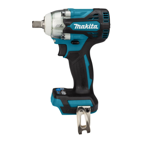
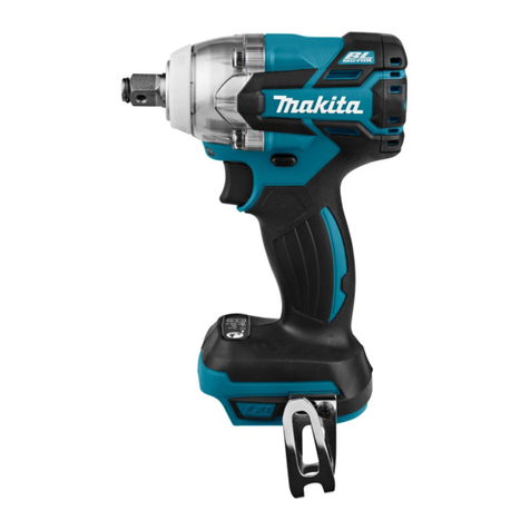
PARTS DESCRIPTION
Fig.1
1 2 3Switch trigger Hanger
5Handle 6 7 8Speed indicator
9 10 11 12 Shoulder harness
