SAFE Y
The Prostream Teat Spray System is designed exclusively for use in milking
installations. Any application outside the use described in this operating
manual will be taken to be not in accordance with the intended purpose.
The manufacturer/supplier will not be held responsible for any losses
arising as a result of such use. The user will take full responsibility for use.
USE IN ACCORDANCE WITH THE INTENDED PURPOSE ALSO INCLUDES
COMPLYING WITH THE OPERATING MANUAL AND THE CONDITIONS
FOR INSPECTION AND MAINTENANCE.
ATTENTION! Whilst in operation the installation is under an operating
pressure of 3 to 4 bar! Do not spray dip into your eyes! If you do, rinse
with copious amounts of water and seek medical attention!
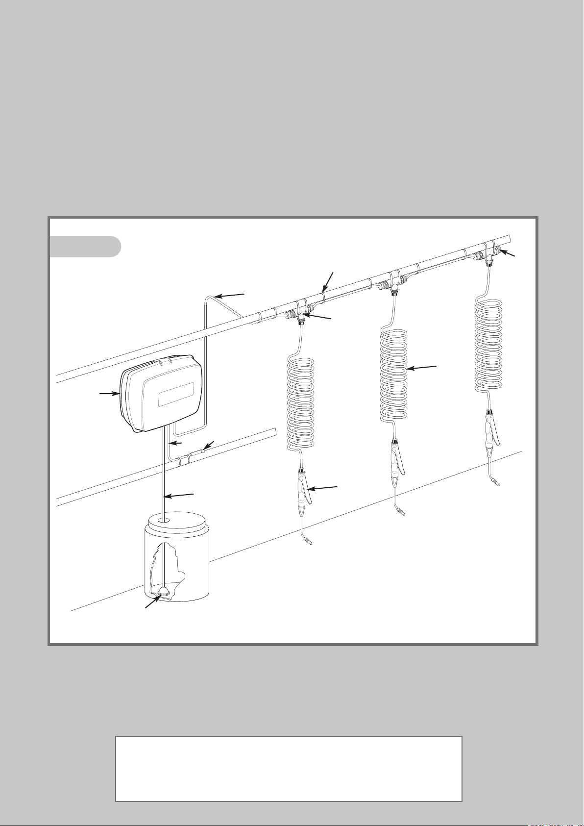
For general parlour layout refer to FIG 1.
Position Power Unit (A) not more than 3 metres (10ft) above the
base of the Chemical Container, preferably in a dust free
environment, close to a regulated Vacuum Line.
The unit will slot onto some existing Wall Brackets. If this is a new
system, fix using 2 x screws and rawlplugs.
Using the drilling template on page 23, fit one screw first then
carefully mark and drill the other. Accuracy between centres is most
important.
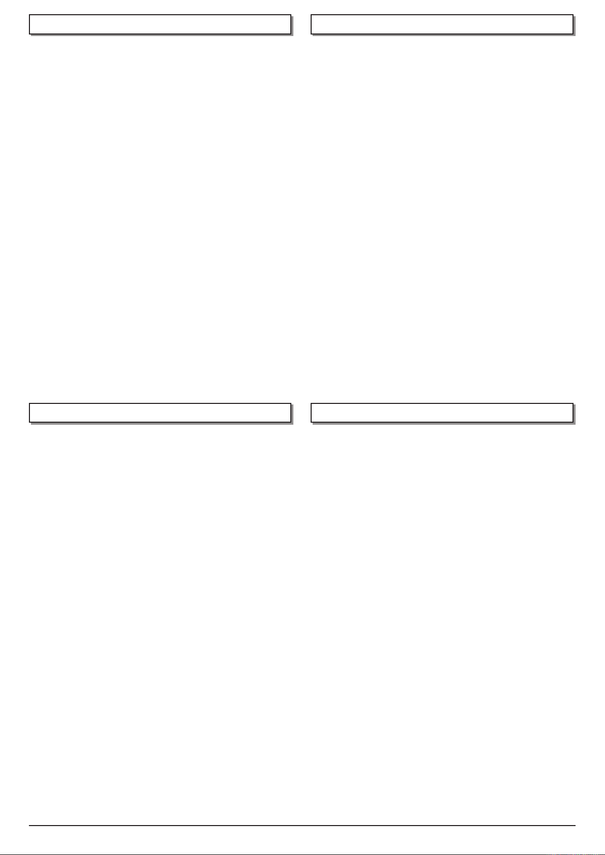
VACUUM SUPPLY Drill a 10mmØ (3/8”Ø) hole in the top of a
regulated main vacuum line (FIG 3). Remove burrs, lubricate Pipe
Adaptor (B) and twist into hole.
Secure Tube (E) with Cable Ties (K). Do not over-tighten and avoid
sharp bends. Cut tube to correct length and push firmly into
Manifold rubber sleeve (FIG 6 ‘A’).
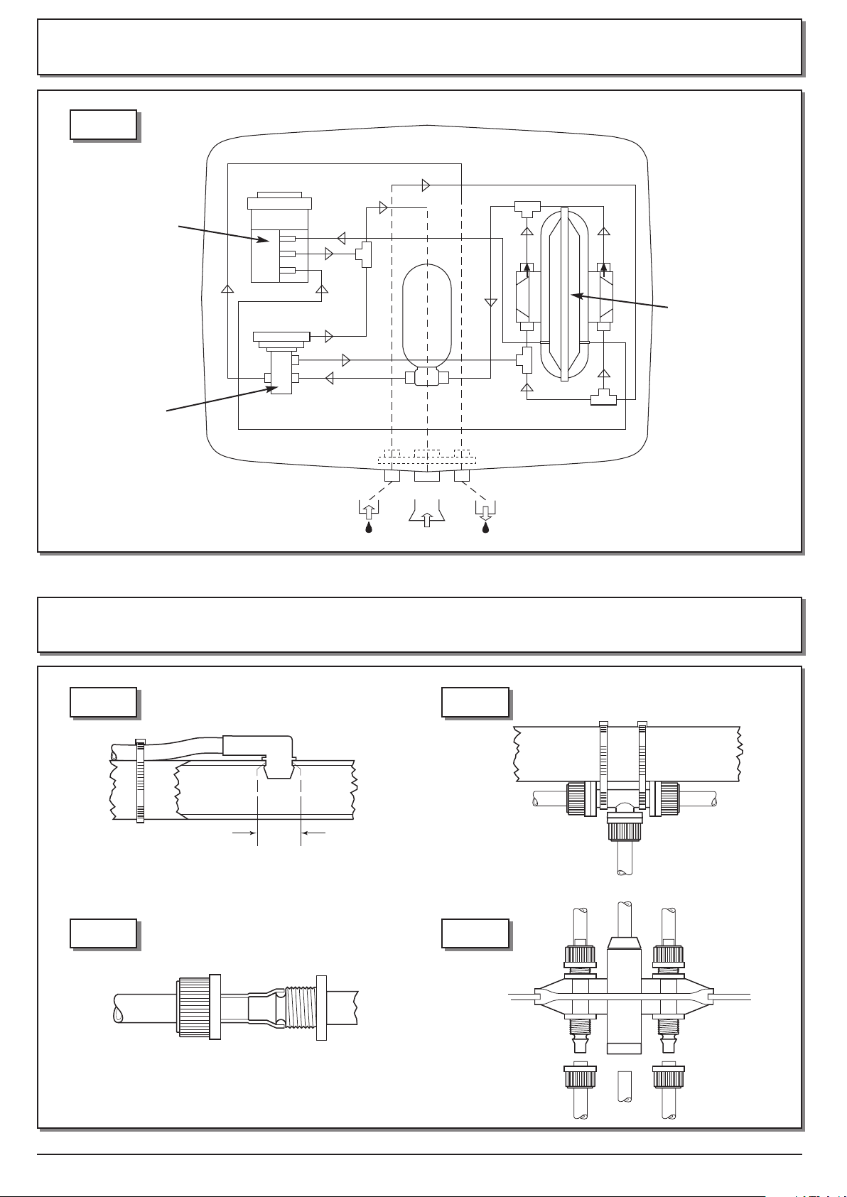
CHEMICAL IN AKE Unscrew Nut and remove Blanking Plug from
intake port (FIG 2). Cut tube (C) to correct length ensuring
that the Intake Filter (D) rests on the bottom of the Chemical
Container.
Insert tube through nut, warm end of tube to ease assembly and
push fully onto port. Tighten nut firmly with fingers. Do not use
pliers or other tools. This method should be used when connecting
all such fittings on Prostream (FIG 5).
PRESSURE LINE Determine position of ‘T’s (G) and strap loosely to a
suitable support (FIG4). Cut suitable lengths of Tubing (F) strapping
and connecting to ‘T’s (G) and outlet port (FIG 2). Attach Coils
(I) and Guns (H). Seal open end of last ‘T’ with Blanking Plug (J) and
Nut.
Finally, once positions are correct, fully tighten Cable Ties. Do not
over-tighten on tubing and avoid sharp bends.
When installation is complete, turn on Vacuum Pump. Power Unit
will automatically start, reaching full pressure within one minute.
There will be some air in the system. To expel this, hold each gun
above the Delivery Line vertically at arms length pointing away from
face. Press button until air bubbles are no longer apparent.
Pro stream is suitable for use with any recognised Teat Disinfectant
except Sodium Hypochlorite and Peroxyacetic Acid. When using
concentrates, ensure that the manufacturers instructions are
followed. Agitation may, periodically, be required.
Important: Replenish disinfectant supply before it runs out to
prevent air entering the system.
SPRAYING For effective Mastitis Pathogen control the teats must be
completely covered with disinfectant.
Rotate nozzle to achieve correct spray pattern (FIG 12). This is
unnecessary with solid cone nozzle.
The nozzle should ideally be positioned approximately 15cm (6”)
below the teats. Optimum and economical coverage is achieved by
employing a circular movement (Fig 13 & 14). Application time will
differ between cows; however, on average should be approximately
1 second per cow.
END OF MILKING When the main Vacuum Supply is turned off, the
Power Unit automatically returns pressurised disinfectant to the
Chemical Container. This ensures immediate safety and also flushes
any debris from the Intake Filter (D).
DIREC IONAL VALVE A S/425 is located at the top left of the
Power Unit (FIG 2). NO E: Most maintenance can be carried out
with the Valve in place.
If complete removal is required, slide out of clips using a twisting
action (Arrow 1 FIG 15). Grasp Valve Manifold and gently pull away
from the Valve (Arrow 2). To refit, reverse the operation.
VALVE FIL ER A S/444 Replace every 1000 hours or sooner if heavily
contaminated. Manually release Valve Filter Cover Clips by levering with
fingers (FIG 8). Carefully remove Valve Filter taking care not to drop dust
into the working parts. Fit new Valve Filter by reversing the process.
BLEED INSER A S/447 Pull out of main body taking care not to
dislodge the 4 ‘O’ Rings. Inspect two small holes near the end
(FIG 9). Clean every 1000 hours or sooner if heavily contaminated.
Use strand of wire attached to bleed insert.
DIAPHRAGM ASSEMBLY A S/443 Replace every 3000 hours. First
remove Valve Filter (see above). Remove Spring ATS/442. Pull Drive
Box in direction of Arrow (FIG 9) using pliers on lug. Unscrew large
black ring nut, gently prise off red cap, using a screwdriver in slot
provided. Pull out Rubber Diaphragm by grasping outer rim. Re-fit
Diaphragm Assembly ATS/443 taking care not to remove the pre-
lubrication on the shaft. If the Spring, ATS/442 shows any sign of
corrosion, replace it.
Fit new Diaphragm Assembly by reversing the operation, ensuring
that the semi circular location engages in the recess on the main
body. When replacing the Drive Box push hard until a click is heard
indicating proper engagement. Prior to fitting the Filter and Cover,
push Drive Box from end to end. An audible click should be heard,
indicating proper operation.
DIAPHRAGM PUMP AJS/2004 The Pump is located on the right
of the Power Unit ‘A’ (FIG 2). It needs no maintenance but, in the
rare event of failure, it is removed by first unscrewing the Pressure
Bottle ATS/436 in the direction of arrow 3 (FIG 15). Remove transit
fixings. Tilt Pump AJS/2004 and unclip by sliding in the direction of
arrows 4 (FIG 15). Remove both rubber elbows. Unscrew 4 Nuts, on
the Pump Head, ATS/445 and ATS/446 (FIG 7), warm Tube ends and
pull off gently, noting their positions.
When replacing the Pump, make sure that the arrows on the Pump
Heads point towards the top of the Power Unit. Occasionally, debris
may enter the Non Return Valves ATS/445 and ATS/446 (FIG 7).
These can be unscrewed using long nosed pliers. Wash out and blow
through. These components can be replaced if damaged.
RELIEF VALVE AJS/2006 is located at bottom left of Power Unit
(FIG 2). To replace Diaphragm ATS/435, unscrew top with moulded
lugs, this will expose Diaphragm for replacement. To fit a different
Pressure Relief Module ‘X’ (FIG 11), AJS/2016, remove rubber elbow
in direction of arrow. Unscrew the complete top inclusive of Spigot
section, this will expose the existing Relief Module.
To replace or remove complete Relief Valve, first remove the Pump as
described under Diaphragm Pump. Then tilt and slide Bottle Holder
in direction of arrow 5 (FIG 15), unclip the Relief Valve in
8
ENGLISH
8. INI IAL S AR UP
7. INS ALLA ION
9. OPERA ION
10. MAIN ENANCE