marklin baureihe V 60 User manual

Baureihe V 60

2Betrieb Seite 7 Operation Page 15 Fonctionnement Page 23 Exploitatie Blz. 31
1Exploitation
Vorbild Seite 5 Prototype Page 5 dans le réel Page 6 Grootbedrijf Blz. 6
3Betrieb auf Operation on Exploitation Bedrijf op
der Anlage Seite 39 a layout Page 39 sur réseau Page 39 een modelbaan Blz. 39
4Wartung Seite 40 Maintenance Page 40 Entretien Page 40 Onderhoud Blz. 40
3

1Vorbild

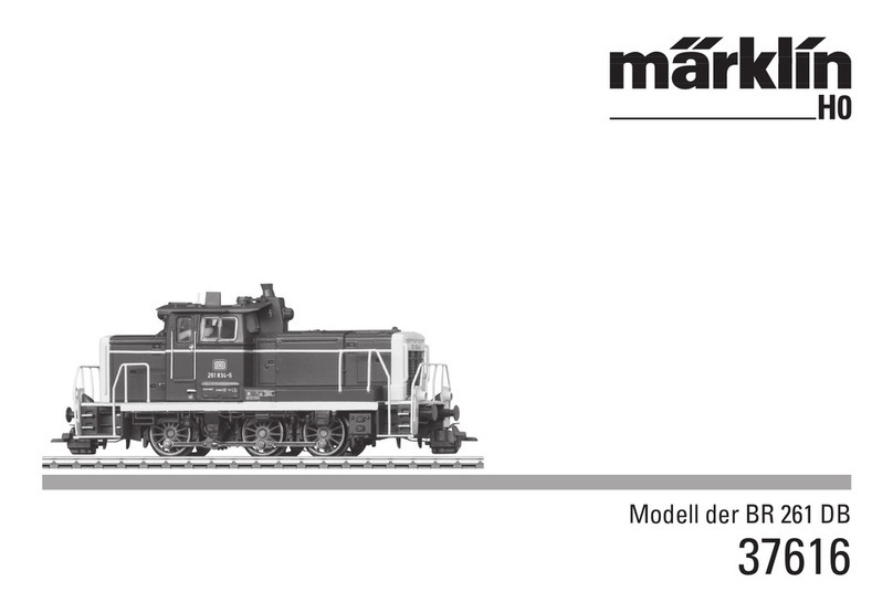
Die Diesel-Rangierlokomotive der Baureihe 260 (V 60)
Zu dem umfangreichen Neubeschaffungsprogramm an Diesel-Lokomotiven
bei der Deutschen Bundesbahn in den 50er-Jahren des 20. Jahrhunderts,
zu denen zum Beispiel auch die V 100 und V 200 als zwei sehr populäre Bau-
reihen gehörten, wurde für den Rangierdienst die dreiachsige Rangierloko-
motive der Baureihe V 60 in großer Zahl beschafft.
Mit einer Leistung von 650 PS erreichte diese Lok eine Spitzengeschwindig-
keit von 60 km/h. Angetrieben über eine Blindwelle mit Kuppelstangen ist diese
Lok einer der letzten Konstruktionen, die diese optisch so beeindruckende
Art der Kraftübertragung besitzt. Die sich bewegenden Kuppelstangen stellen
eben die visualisierte Dynamik dar.
Ab 1968 wurden diese Modelle in BR 260 umbenannt. Später wurde ein
Großteil der Modelle mit Fernsteuerung ausgestattet und als Kleinlokomotive
eingestuft. Dadurch durften auch angelernte Rangierkräfte diese Rangier-
lokomotive steuern.
The Class 260 (V 60) Diesel Switch Engine
The extensive new diesel locomotive program on the German Federal Railroad
in the 1950s included the popular classes V 100 and V 200. The class V 60
3-axle diesel switch engine was ordered in large quantities for switching work.
This locomotive had a power output of 650 hp and reached a maximum
speed of 60 km/h or 38 mph. It was powered by a jackshaft with side rods
and was one of the last designs to have this visually impressive form of power
transmission. The side rods in motion represent by themselves the dynamic
motion of the locomotive.
Starting in 1968 this model was reclassified as the class 260. Later a large
number of these models were equipped for remote control and were grouped
as small locomotives. This made it possible for even newly trained switch
engine crews to control these units.
1
5
Vorbild Prototype

La locomotive diesel de manoeuvre de la série 260 (V 60)
Dans le cadre de l’ambitieux programme de renouvellement des moyens de
traction diesel développépar la Deutsche Bundesbahn au cours des années
cinquante du siècle passé, lequel comprenait entre autres la fourniture des
très populaires séries V 100 et V 200, on a commandéun grand nombre de
machines de manœuvre àtrois essieux de la série V 60.
Développant une puissance de 650 CV, cette locomotive pouvait atteindre la
vitesse de 60 km/h. Cette machine, dotée d’un moteur entraînant les essieux
au moyen d’un faux-essieu et de bielles d’accouplement, était une des der-
nières constructions munies d’un tel dispositif d’entraînement au fonctionne-
ment assez impressionnant.
A partir de 1968, la série V 60 est devenue la série 260. Une grande partie
des machines a étédotée par la suite d’un équipement de télécommande
et classées dans la catégorie des petites locomotives, ce qui a nécessitéla
formation d’ouvriers qualifiés pour leur pilotage.
De diesel-rangeerlocomotief van de serie 260 (V60)
Tot het omvangrijke aankoopprogramma van nieuwe diesellocomotieven bij
de Deutschen Bundesbahn in de vijftiger jaren van de 20ste eeuw, waartoe
ook bijvoorbeeld de populaire serie V100 en V200 behoorden, werd voor de
rangeerdienst de drie-assige rangeerlocomotief serie V60 in grote aantallen
aangekocht.
Met een vermogen van 650 pk bereikte de loc een topsnelheid van 60 km/h.
Aangedreven door een zgn. ”blindwiel”en koppelstangen is deze loc één
van de laatste constructies die deze op het oog indrukwekkende wijze van
krachtoverbrenging bezit. De bewegende koppelstangen geven nu eenmaal
een dynamisch beeld.
Vanaf 1968 werden deze modellen omgenummerd in de serie 260. Later
werd een groot deel van de machines voorzien van een afstandsbesturing
en als locomotor aangemerkt. Hierdoor mochten ook daarvoor opgeleide
rangeerders deze locomotieven besturen.
6
1Exploitation dans le réel Grootbedrijf

7
Betrieb
2.1 Funktion
Diese Lok mit eingebauter
Digital-Elektronik bietet:
•Wahlweise konventioneller Wech-
selspannungs- (Transformer 32 VA)
oder Gleichspannungs-Betrieb
(max. 18 V=) sowie Märklin Delta
(nur Delta Station 6607) oder
Märklin Digital (Motorola-Format).
Ein Betrieb mit Fahrgeräten anderer
Systeme (z.B. Impulsbreiten-
steuerung, Betrieb mit der Central
Control 1 (6030) oder ähnlichem
System) ist nicht möglich.
•Automatische Erkennung zwischen
konventionellem und Digital-/Delta-
Betrieb. Die Auswahl zwischen
Wechselspannung und Gleich-
spannung beim konventionellen
Betrieb wird manuell auf der Platine
eingestellt.
•80 Digital- (4 Delta-) Adressen
über Codierschalter einstellbar.
Eingestellte Adresse ab Werk: 60
•Einstellbare Höchstgeschwindigkeit.
•Einstellbare Anfahr-/ Bremsver-
zögerung. Bremsverzögerung im
konventionellen Betrieb system-
bedingt nicht wirksam.
•Fahrtrichtungsabhängige Spitzen-
beleuchtung im Digital-Betrieb
ein-/ausschaltbar. Bei konventio-
nellem Betrieb ist die Intensität
der Beleuchtung geschwindig-
keitsabhängig. Bei Betrieb mit
Delta-Station ist die Spitzenbe-
leuchtung dauernd eingeschaltet.
•Eingebaute Geräuschelektronik,
bei der nur im Digital-Betrieb mit
der Control-Unit 6021 das
Betriebsgeräusch oder separat
das Geräusch eines Signalhorns
eingeschaltet werden kann.
•Ausgerüstet mit Telex-Kupplung
vorne und hinten zum fernbedien-
ten Abkuppeln von angehängten
Maxi- oder Profi1-Wagen mit
montierter Märklin Klauenkupplung.
Diese Kupplungen sind nur im
Digitalbetrieb mit der Control-Unit
6021 als Zentraleinheit schaltbar.
Eine Funktion der Telex-Kupplung
mit Kupplungssystemen anderer
Hersteller ist nicht gewährleistet.
•Befahrbarer Mindestradius:
600 mm. Dieser Radius kann
jedoch nur mit erheblich vermin-
derter Geschwindigkeit befahren
werden.
•Das Modell ist für den Betrieb auf
dem Märklin Maxi oder Profi1-
Gleissystem entwickelt. Ein Betrieb
auf anderen Gleissystemen
geschieht auf eigenes Risiko.
2
Betrieb
8
2
2.2 Einstellen der Betriebsart
oder Digital-/Delta-Adresse
Schritt 1:
Vorderbau abnehmen (=> S. 40)
Die Betriebsart oder die Digital-/
Delta-Adresse wird an dem 10-fach
Codierschalter auf der Digital-
elektronik eingestellt.
Vorsicht! Den 10-fach Codier-
schalter für die Betriebsart und
für die Adresse auf der unteren
Digital-Platine nicht mit dem
8-fach Codierschalter auf der
oberen Soundplatine verwechseln!
2.2.1 Betriebsart einstellen
Schritt 2:
Die analoge Betriebsart wird am
Schalter 10 (Bezeichnung „0“) des
10-fach Codierschalters eingestellt.
Schalter 10 (0) auf off:
Wechselspannung
Schalter 10 (0) auf on:
Gleichspannung
Die Betriebsart Märklin Digital bzw.
Delta wird automatisch von der
Elektronik erkannt.
Hinweis:
Der Schalter 9 muss immer in
Stellung „off“stehen.
2.2.2 Digital-/Delta-Adresse
einstellen
Schritt 2:
Die Digital-/Delta-Adresse wird an
den Schaltern 1 bis 8 des 10-fach
Codierschalters eingestellt.
Beispiel: gewünschte Adresse „60“
Schalter 1, 5: Stellung on
Schalter 2, 3, 4, 6, 7, 8: Stellung off
Hinweis:
Die Digitaladressen 24, 60, 72
und 78 entsprechen den vier Delta-
Adressen.

2
9
Betrieb
Digital Digital Digital
28 –2 3 –5 ––8 –*
29 ––3 –5 ––8 –*
30 1 ––4 5 ––8 –*
31 –2 –4 5 ––8 –*
32 –––4 5 ––8 –*
33 1 –––5 ––8 –*
34 –2 ––5 ––8 –*
35 ––––5 ––8 –*
36 1 –3 ––6 –8 –*
37 –2 3 ––6 –8 –*
38 ––3 ––6 –8 –*
39 1 ––4 –6 –8 –*
40 –2 –4 –6 –8 –*
41 –––4 –6 –8 –*
42 1 ––––6 –8 –*
43 –2 –––6 –8 –*
44 –––––6 –8 –*
45 1 –3 ––––8 –*
46 –2 3 ––––8 –*
47 ––3 ––––8 –*
48 1 ––4 –––8 –*
49 –2 –4 –––8 –*
50 –––4 –––8 –*
51 1 ––––––8 –*
52 –2 –––––8 –*
53 –––––––8 –*
54 1 –3 –5 ––––*
55 –2 3 –5 ––––*
56 ––3 –5 ––––*
57 1 ––4 5 ––––*
58 –2 –4 5 ––––*
59 –––4 5 ––––*
60 1 –––5 ––––*
61 –2 ––5 ––––*
62 ––––5 ––––*
63 1 –3 ––6 –––*
64 –2 3 ––6 –––*
65 ––3 ––6 –––*
66 1 ––4 –6 –––*
67 –2 –4 –6 –––*
68 –––4 –6 –––*
69 1 ––––6 –––*
70 –2 –––6 –––*
71 –––––6 –––*
72 1 –3 ––––––*
73 –2 3 ––––––*
74 ––3 ––––––*
75 1 ––4 –––––*
76 –2 –4 –––––*
77 –––4 –––––*
78 1 ––––––––*
79 –2 –––––––*
80 1 –3 –5 –7 ––*
01 –2 3 –5 –7 ––*
02 ––3 –5 –7 ––*
03 1 ––4 5 –7 ––*
04 –2 –4 5 –7 ––*
05 –––4 5 –7 ––*
06 1 –––5 –7 ––*
07 –2 ––5 –7 ––*
08 ––––5 –7 ––*
09 1 –3 ––6 7 ––*
10 –2 3 ––6 7 ––*
11 ––3 ––6 7 ––*
12 1 ––4 –6 7 ––*
13 –2 –4 –6 7 ––*
14 –––4 –6 7 ––*
15 1 ––––6 7 ––*
16 –2 –––6 7 ––*
17 –––––6 7 ––*
18 1 –3 –––7 ––*
19 –2 3 –––7 ––*
20 ––3 –––7 ––*
21 1 ––4 ––7 ––*
22 –2 –4 ––7 ––*
23 –––4 ––7 ––*
24 1 –––––7 ––*
25 –2 ––––7 ––*
26 ––––––7 ––*
27 1 –3 –5 ––8 –*
~
90
=
90
*Je nach Stellung konventioneller
Wechselstrom (off)
Gleichstrombetrieb (on).

2.3 Einstellen
der Fahrparameter
1. Vorderbau abnehmen (=> S. 40)
2. Durch Verändern der Stellung der
Potis auf der unteren Platine können
Sie die Fahrparameter verändern. Die
Drehpotis besitzen an den Endposi-
tionen jeweils einen Anschlag. Daher
bei Widerstand beim Drehen der
Potis nicht mit Gewalt weiterdrehen.
P1: Anfahr-/ Bremsverzögerung
(gemeinsam)
Linksanschlag: minimale Verzögerung.
Rechtsanschlag: maximale Verzöge-
rung.
P2: Höchstgeschwindigkeit
Linksanschlag: minimale Höchstge-
schwindigkeit.
Rechtsanschlag: maximale Höchst-
geschwindigkeit.
Hinweis:
Die beiden Potis zum Einstellen
der Fahrparameter auf der unteren
Digital-Platine nicht mit dem Poti
zur Lautstärkeregelung auf der
oberen Platine verwechseln.
10
2Betrieb
P2
P1

2.4 Betrieb mit den einzelnen
Versorgungs-Systemen
2.4.1 Digital
Hinweis:
Zum Fahrbetrieb können alle Märklin
Zentraleinheiten mit dem Motorola-
Übertragungsformat verwendet wer-
den. Der volle Funktionsumfang steht
jedoch nur mit der Control-Unit 6021
zur Verfügung. Bei Verwendung der
früheren Central-Unit 6020 oder einer
baugleichen Version können die
Funktionen F1 bis F4 nicht geschaltet
werden. Es entfällt auch die Fahrt-
richtungsanzeige.
Für einen einwandfreien Betrieb mit
der Control-Unit 6021 müssen die
Codierschalter auf der Rückseite dieses
Gerätes in folgende Stellung gebracht
werden:
Schalter: 1 2 3 4
Stellung: on on on off
Fahrbetrieb mit der
Control-Unit 6021:
Lokadresse eingeben. Drehen des
Fahrreglers nach rechts bis zum
Anschlag erhöht die Lokgeschwin-
digkeit. Drehen des Fahrreglers nach
links bis zur Stellung „0“vermindert
die Lokgeschwindigkeit.
Hinweis:
Je nach eingestellter Anfahr-/ Brems-
verzögerung reagiert die Lok ent-
sprechend zeitverzögert auf die neue
Vorgabe. Drehen des Fahrreglers
nach links über die Stellung „0“hin-
weg: Fahrtrichtungswechsel.
Hinweis:
Die Fahrtrichtung wird bei der
Control-Unit 6021 über zwei Pfeile
rechts neben der Adressanzeige
angezeigt.
Pfeil nach oben: Lok fährt vorwärts.
Pfeil nach unten: Lok fährt rückwärts.
Drücken der Taste „function“:
Einschalten der Beleuchtung.
Drücken der Taste „off“:
Ausschalten der Beleuchtung.
Drücken der Taste „f2“:
Einschalten der Geräuschelektronik
(Betriebsgeräusch).
Durch ein weiteres Betätigen der
Taste „f2“wird das Geräusch wieder
ausgeschaltet.
Drücken der Taste „f3“:
Einschalten des Geräuschs eines
Signalhorns. Anschließend unbe-
dingt durch ein weiteres Betätigen
der Taste „f3“die Funktion aus-
schalten! Sonst kann es zu Fehlfunk-
tionen kommen.
Drücken der Taste „f4“:
Die Telex-Kupplung vorne und hinten
wird eingeschaltet. Ein weiteres
Betätigen der Taste „f4“schaltet die
Telex-Kupplungen wieder aus.
Wichtiger Hinweis:
Die Telex-Kupplungen dürfen nicht
dauerhaft eingeschaltet sein (Über-
hitzungsgefahr des Antriebs). Daher
sind sie mit einer Schutzschaltung
gegen eine zu lange Betätigung
gesichert. Gewöhnen Sie sich bitte
unbedingt an, die Telex-Kupplung
nur so lange wie notwendig einzu-
schalten.
2
11
Betrieb

12
2Betrieb
2.4.2 Fahren der Lok mit Delta
Zum Fahren der Lok mit Märklin
Delta wird an dem Handregler
Delta-Mobil die eingestellte Lok-
adresse angewählt. Durch Drehen
des Fahrreglers aus der Mittelstellung
heraus nach rechts fährt die Lok vor-
wärts. Durch Drehen des Fahrreglers
aus der Mittelstellung nach links fährt
die Lok rückwärts. Die fahrtrichtungs-
abhängige Beleuchtung ist dauernd
eingeschaltet. Die maximale Aus-
gangsleistung der Delta-Station
reicht zum gleichzeitigen Fahren von
2 bis maximal 3 einmotorigen Loko-
motiven.
Alle sonstigen Funktionen (Geräusch,
Telex) sind im Delta-Betrieb immer
ausgeschaltet.
2.4.3 Fahren mit Wechselspannung
In der Betriebsart „Wechselspannung“
kann die Lok z.B. mit dem Transfor-
mer 32 VA (Nr. 6645, 6646, 6647
oder 76648) gesteuert werden.
Durch Drehen des Fahrreglers nach
rechts wird die Geschwindigkeit der
Lok erhöht und durch Drehen nach
links wird sie entsprechend vermin-
dert. Wird der Fahrregler über die
Stellung „0“nach links weiter
gedreht, so wird die Fahrtrichtung
umgeschaltet. Der Umschaltbefehl
für die Fahrtrichtung sollte nie an eine
fahrende Lok sondern immer nur an
eine stehende Lok gegeben werden.
Alle sonstigen Funktionen (Geräusch,
Telex) sind im Wechselspannungs-
Betrieb immer ausgeschaltet.
2.4.4 Fahren mit Gleichspannung
Gleichspannungs-Fahrgeräte werden
von Märklin für Spur-1-Modelle nicht
angeboten. Geeignet sind Gleich-
spannungs-Fahrgeräte mit einer
maximalen Spannung von ±18 Volt.
Der Fahrtrichtungswechsel wird
durch einen Polaritätswechsel vorge-
nommen. Die Bedienung des jeweili-
gen Fahrgerätes entnehmen Sie der
Anleitung des Herstellers.
Hinweis:
H0-Gleichspannungs-Fahrgeräte
geben eine maximale Spannung von
±12 Volt ab. Die Lok erreicht jedoch
ihre volle Leistungsfähigkeit erst bei
±16 Volt. H0-Gleichspannungs-Fahr-
geräte sind daher nur eingeschränkt
verwendbar.
Im Betrieb mit Gleichspannung ist die
fahrtrichtungsabhängige Beleuchtung
eingeschaltet. Die Intensität der Be-
leuchtung ist geschwindigkeitsab-
hängig.
Alle sonstigen Funktionen (Geräusch,
Telex) sind im Gleichspannungs-
Betrieb immer ausgeschaltet.

2.5 Einstellen der
Geräuschelektronik
Für die nachfolgenden Einstell-
arbeiten ist der Vorderbau der Lok
abzunehmen (=> S. 40). Die obere
der beiden Platinen ist die Sound-
Elektronik, auf der Sie nachfolgende
Einstellungen durchführen können.
2.5.1 Lautstärke einstellen
Hinweis: Dieses Poti befindet sich
auf der oberen Sound-Elektronik.
Verwechseln Sie auf keinen Fall
dieses Poti mit einem der Potis auf
der unteren Digital-Platine zum
Einstellen der Fahrparameter.
Drehen des Potis nach links: Lauter
Drehen des Potis nach rechts: Leiser
Das Poti besitzt an den Endpunkten
jeweils einen Anschlag. Versuchen
Sie nie mit Kraft das Poti über diesen
Anschlag hinweg zu drehen.
2.5.2 Codierschalter auf der
Sound-Elektronik
Die Soundelektronik wird mit dem
8-poligen Codierschalter auf das
jeweilige Modell abgestimmt. Die
passende Einstellung für Ihr Modell
ist dabei ab Werk eingestellt. Daher
ist keine Veränderung der Einstellung
notwendig.
Hinweis:
Dieser Codierschalter befindet
sich auf der oberen Sound-
Elektronik. Verwechseln
Sie ihn auf keinen Fall mit dem
10-fach Codierschalter zum Ein-
stellen der Adresse und Betriebs-
art auf der unteren Digital-
Elektronik.
Die Serieneinstellung der 8 Codier-
schalter ist:
Schalter 1 2 3 4 5 6 7 8
Stellung On On On Off On On On On
2
13
Betrieb

14
2Betrieb
Nur zu Ihrer Information nachfolgend die Funktion der einzelnen Schalter:
Schalter Stellung = on Stellung = off Bemerkung
1 Muss immer auf „on“stehen! Darf nie auf „off stehen! Nie verändern!
2 Muss immer auf „on“stehen! Darf nie auf „off stehen! Nie verändern!
3 F3: Signalhorngeräusch einer F3: Signalhorngeräusch einer
Rangierlokomotive Streckenlokomotive
4 F4: Geräusch einer Signalglocke F4: Schalten der Telex-Kupplung(en)
5 F1: Geräusch einer Signalglocke F1: Wiedergabe der nicht mit Schalter 3 Auswahl nur wirksam, wenn
ausgewählten Signalhorn-Version Schalter 6 und 8 auf „off“gestellt sind
6 F1: Wiedergabe des Betriebs- F1: Wiedergabe des mit Auswahl nur wirksam, wenn
geräusches eines zweiten Motors Schalter 5 ausgewählten Geräuschs Schalter 8 auf „off“gestellt ist
7 F2: Betriebsgeräusch von F2: Betriebsgeräusch von
einer Lok mit einem Motor einer Lok mit zwei Motoren.
8 F1: Keine Geräuschausgabe F1: Mit Geräuschausgabe Nur bei ausschließlichem Digital-
betrieb Schalter 8 auf „off“schalten.

2.1 Function
This locomotive has a built-in digital
electronic circuit and offers the follo-
wing features:
•Operation with AC power (32 VA
transformer) or DC power (max.
18 volts DC) as well as Märklin
Delta (6607 Delta Station only) or
Märklin Digital (Motorola format).
This locomotive is not designed for
operation with locomotive control-
lers for other systems (example:
pulse width control, operation with
the Central Control 1 (6030) or
similar systems).
•Automatic recognition of conven-
tional and Digital/ Delta operation.
The choice between AC or DC
power in conventional operation is
set manually on the circuit board.
•80 Digital (4 Delta) addresses can
be set with coding switches.
Address set at the factory: 60
•Adjustable maximum speed
•Adjustable acceleration/braking
delay. The electronic circuit for the
locomotive is designed in such a
way that the braking delay will not
work in conventional operation.
•Headlights change over with the
direction of travel and can be tur-
ned on and off in Digital operation.
During conventional operation the
brightness of the headlights de-
pends on the speed of the loco-
motive. The headlights are on
constantly when the locomotive is
operated with the Delta Station.
•Built-in sound effects circuit,
which can be used to turn on the
locomotive’s operating sounds or
the sound of a horn. This can only
be done in digital operation with
the 6021 Control Unit.
•Equipped with Telex couplers front
and rear for remote control uncou-
pling from Maxi or standard 1
Gauge cars with the Märklin claw
coupler mounted on them. These
Telex couplers can be turned on
and off only when the locomotive
is used in digital operation with the
6021 Control Unit as a Central
Unit. We cannot guarantee that
the Telex couplers will work with
other makes of couplers.
•Minimum radius for operation:
600 mm / 23-5/8“. The locomotive
can run on this radius only at con-
siderably lower speeds.
•This model was designed for ope-
ration on the Märklin Maxi or
Standard 1 Gauge Track System.
You incur your own risk operating
it on other track systems.
2
15
Operation

2.2 Setting the Mode of
Operation or Digital/Delta
Address
Step 1:
Remove the front hood (=> Page 40)
The mode of operation or the
Digital/Delta address is set with the
10 coding switches on the digital
electronic circuit.
Caution! Do not confuse the
10 coding switches for the mode
of operation and for the address
on the lower digital circuit board
with the 8 coding switches on the
upper sound effects circuit board!
2.2.1 Setting the Mode of
Operation
Step 2:
The analog mode of operation is set
with switch 10 (designated “0”) of the
10 coding switches.
Switch 10 (0) at off: AC current
Switch 10 (0) at on: DC current
The mode of operation for Märklin
Digital or Delta is automatically
recognized by the electronic circuit.
Important:
Switch 9 must always be kept at
the “off”setting.
2.2.2 Setting Digital/Delta
Address
Step 2:
The Digital/Delta address is set with
switches 1 through 8 of the 10
coding switches.
Example: “60”as the desired address
Switch 1, 5: on position
Switch 2, 3, 4, 6, 7, 8: off position
Important:
The digital addresses 24, 60, 72,
nd 78 correspond to the four Delta
addresses.
16
2Operation

2
17
Operation
~
90
=
90
*Conventional AC power (off) or
DC power (on), depending on the
setting.
Digital Digital Digital
28 –2 3 –5 ––8 –*
29 ––3 –5 ––8 –*
30 1 ––4 5 ––8 –*
31 –2 –4 5 ––8 –*
32 –––4 5 ––8 –*
33 1 –––5 ––8 –*
34 –2 ––5 ––8 –*
35 ––––5 ––8 –*
36 1 –3 ––6 –8 –*
37 –2 3 ––6 –8 –*
38 ––3 ––6 –8 –*
39 1 ––4 –6 –8 –*
40 –2 –4 –6 –8 –*
41 –––4 –6 –8 –*
42 1 ––––6 –8 –*
43 –2 –––6 –8 –*
44 –––––6 –8 –*
45 1 –3 ––––8 –*
46 –2 3 ––––8 –*
47 ––3 ––––8 –*
48 1 ––4 –––8 –*
49 –2 –4 –––8 –*
50 –––4 –––8 –*
51 1 ––––––8 –*
52 –2 –––––8 –*
53 –––––––8 –*
54 1 –3 –5 ––––*
55 –2 3 –5 ––––*
56 ––3 –5 ––––*
57 1 ––4 5 ––––*
58 –2 –4 5 ––––*
59 –––4 5 ––––*
60 1 –––5 ––––*
61 –2 ––5 ––––*
62 ––––5 ––––*
63 1 –3 ––6 –––*
64 –2 3 ––6 –––*
65 ––3 ––6 –––*
66 1 ––4 –6 –––*
67 –2 –4 –6 –––*
68 –––4 –6 –––*
69 1 ––––6 –––*
70 –2 –––6 –––*
71 –––––6 –––*
72 1 –3 ––––––*
73 –2 3 ––––––*
74 ––3 ––––––*
75 1 ––4 –––––*
76 –2 –4 –––––*
77 –––4 –––––*
78 1 ––––––––*
79 –2 –––––––*
80 1 –3 –5 –7 ––*
01 –2 3 –5 –7 ––*
02 ––3 –5 –7 ––*
03 1 ––4 5 –7 ––*
04 –2 –4 5 –7 ––*
05 –––4 5 –7 ––*
06 1 –––5 –7 ––*
07 –2 ––5 –7 ––*
08 ––––5 –7 ––*
09 1 –3 ––6 7 ––*
10 –2 3 ––6 7 ––*
11 ––3 ––6 7 ––*
12 1 ––4 –6 7 ––*
13 –2 –4 –6 7 ––*
14 –––4 –6 7 ––*
15 1 ––––6 7 ––*
16 –2 –––6 7 ––*
17 –––––6 7 ––*
18 1 –3 –––7 ––*
19 –2 3 –––7 ––*
20 ––3 –––7 ––*
21 1 ––4 ––7 ––*
22 –2 –4 ––7 ––*
23 –––4 ––7 ––*
24 1 –––––7 ––*
25 –2 ––––7 ––*
26 ––––––7 ––*
27 1 –3 –5 ––8 –*

2.3 Setting the Running
Characteristics
1. Removing the front hood
(=> Page 40)
2. You can change the locomotive’s
running characteristics by changing
the settings for the potentiometers
on the lower circuit board. These
potentiometers have a stop at the
end positions. When you encounter
resistance when turning the “pots”,
do not try to turn them further with
force.
P1: Acceleration/braking delay
(together)
Left stop: minimum delay
Right stop: maximum delay
P2: Maximum speed
Left stop: lowest maximum speed
Right stop: highest maximum speed
Important:
Do not confuse the two potentio-
meters for setting the running
characteristics on the lower digital
circuit board with the potentio-
meter for adjusting the volume of
the sound effects on the upper
circuit board.
18
2Operation
P2
P1

2
19
Operation
2.4 Operation with the
Different Power Systems
2.4.1 Digital
Important:
All of the Märklin central units with
the Motorola transmission format can
be used to run this locomotive. The
full range of functions is only available
with the 6021 Control Unit 6021.
Functions f1 through f4 cannot be
activated if you are using the earlier
Central Unit 6020 or a similar version.
The indicator for direction of travel is
also not present on these units.
The coding switches on the back of
the 6021 Control Unit must be set as
follows for trouble free operation:
Switch: 1 2 3 4
Setting: on on on off
Operating the locomotive with the
6021 Control Unit:
Entering the locomotive address.
Turning the speed control knob to
the right to the stop increases the
locomotive’s speed. Turning the
speed control knob to the left to the
"0”setting decreases the locomoti-
ve’s speed.
Important:
There will be a delay in the locomoti-
ve’s reaction to each change in
speed, depending on how you have
set the acceleration/braking delay.
Turning the speed control knob to
the left past the “0”setting: Reverses
the locomotive’s direction of travel.
Important:
On the 6021 Control Unit two arrows
to the right of the address display
indicate the direction of travel for the
locomotive.
Arrow pointing up:
Locomotive runs forward.
Arrow pointing down:
Locomotive runs in reverse.
Pressing the “function”button:
Turns the headlights on.
Pressing the “off”button:
Turns the headlights off.
Pressing button “f2”:
Turns the sound effects circuit on
(locomotive operating sounds).
Pressing button “f2”again turns the
sound effects off.
Pressing button “f3”:
Turns the sound of a horn on. Now
quickly turn this function off by
pressing button “f3”again! Otherwise,
it can lead to malfunctions.
Pressing button: “f4”:
The Telex couplers front and rear are
turned on. Pressing button “f4”again
turns the Telex couplers off.
Important:
The Telex couplers should not be left
on continuously because there is a
danger of overheating the coupler
solenoids. For that reason they are
protected with a circuit against being
on too long. Please accustom your-
self to turning the Telex couplers on
only as long as necessary.

2.4.2 Operating the locomotive
with Delta
To operate the locomotive with Märklin
Delta you use the Delta-Mobil to sel-
ect the address, that has been set on
the former. The locomotive will run
forward when you turn the speed
control knob to the right of the center
position. Turning the speed control
knob to the left of the center position
will cause the locomotive to run in
reverse. The headlights change
direction with the direction of travel
and are on all of the time. The
maximum power output of the
Delta-Station is sufficient to operate
2 to a maximum of 3 single motor
locomotives at the same time.
All other functions (sound effects,
Telex) are always turned off in Delta
operation.
2.4.3 Operating the locomotive
on alternating current
When the locomotive is operated with
AC power in conventional operation,
the 32 VA transformer (no. 6645,
6646, 6647 or 76648) can be used.
Locomotive speed is increased by
turning the control knob to the right
and is decreased by turning the knob
to the left. The direction of travel is
changed by turning the control knob
to the left past the “0”setting.
The command to reverse should be
given only to a standing locomotive,
never to one in motion.In operation
with alternating current the headlights
change direction with the direction of
travel and are on all of the time. The
intensity of the headlights depends
on the speed of the locomotive.
All other functions (sound effects,
Telex) are always turned off in AC
power operation.
2.4.4 Operating the locomotive
on direct current
Märklin does not offer DC power
packs for 1 Gauge models. Suitable
DC power packs are those with a
maximum current of ±18 volts.
Direction reversing is done by rever-
sing polarity. The manufacturerís
instructions for a particular make of
power pack will give directions on
how to use it to operate a locomotive.
Tip:
H0 DC power packs supply a maxi-
mum voltage of ±12 volts. This loco-
motive reaches its full potential at
±16 volts. H0 DC power packs can
therefore be used only with limitations.
In operation with direct current the
headlights change direction with the
direction of travel and are on all of
the time. The intensity of the head-
lights depends on the speed of the
locomotive.
All other functions (sound effects,
Telex) are always turned off in DC
power operation.
20
2Operation

2
21
Operation
2.5 Adjusting the Sound
Effects Circuit
The front hood on the locomotive
must be removed for the following
adjustment work (=> Page 40). The
upper circuit board of the two circuit
boards is the sound effects electronic
circuit on which you can carry out the
following adjustments.
2.5.1 Adjusting Volume
Important: This potentiometer is
located on the upper sound
effects electronic circuit board.
Under no circumstances should
you confuse this potentiometer
with one of the potentiometers on
the lower digital circuit board for
adjusting the running characte-
ristics of the locomotive.
Turning the potentiometer to the left:
louder
Turning the potentiometer to the
right: softer
This potentiometer has a stop at the
two end points. Never try to turn the
potentiometer with force past these
stops.
2.5.2 Coding Switches on the
Sound Effects Electronic
Circuit
The sound effects electronic circuit is
set up for each model with the 8
coding switches. The appropriate
settings for your model were made at
the factory. No changes in these
settings are therefore necessary.
Important: These coding switches
are located on the upper electronic
circuit for sound effects. Under no
circumstances should you confuse
them with the 10 coding switches
for setting the address and the
mode of operation on the lower
digital electronic circuit.
The 8 coding switches are set at the
factory as follows:
Switch 1 2 3 4 5 6 7 8
Setting On On On Off On On On On
Table of contents
Languages:
Other marklin Toy manuals

marklin
marklin 37439 User manual

marklin
marklin 29100 User manual

marklin
marklin 72020 User manual

marklin
marklin 37786 User manual

marklin
marklin 74460 User manual

marklin
marklin 26559 User manual

marklin
marklin Ce 6/8 III Krokodil Series User manual

marklin
marklin 36826 User manual

marklin
marklin 7244 User manual

marklin
marklin Kleinstation User manual

marklin
marklin 43545-04 User manual

marklin
marklin 29210 User manual

marklin
marklin 39671 User manual

marklin
marklin BR 44-OI User manual

marklin
marklin 37124 User manual

marklin
marklin 24194 User manual

marklin
marklin 37578 User manual

marklin
marklin 48293 User manual

marklin
marklin 43570 User manual

marklin
marklin 37257 User manual