Master DH-720 Manual

Edition 14
DH 720
USER AND MAINTENANCE BOOK
LIBRETTO USO E MANUTENZIONE
BEDIENUNGS- UND WARTUNGSANLEITUNG
MANUAL DE INSTRUCCIONES PARAEL USO Y MANTENIMIENTO
MANUEL D’UTILISATION ET DE MAINTENANCE
HANDLEIDING VOOR GEBRUIK EN ONDERHOUD
MANUAL DE USO E MANUTENÇÃO
VEJLEDNING OM BRUG OG VEDLIGEHOLDELSE
KÄYTTÖ- JA HUOLTO-OHJE
HEFTE FOR BRUK OG VEDLIKEHOLD
ANVÄNDAR- OCH UNDERHÅLLSHANDBOK
INSTRUKCJA OBSŁUGI I KONSERWACJI
РУКОВОДСТВО ПО ЭКСПЛУАТАЦИИ И ТЕХНИЧЕСКОМУ ОБСЛУЖИВАНИЮ
PŘÍRUČKA PRO POUŽITÍ A ÚDRŽBU
HASZNÁLATI ÉS KARBANTARTÁSI KÉZIKÖNYV
PRIROČNIK Z NAVODILI ZA UPORABO IN VZDRŽEVANJE
KNJIŽICA O UPORABI I ODRŽAVANJU
NAUDOJIMO IR PRIEŽIŪROS KNYGELE
LIETOŠANAS UN TEHNISKĀS APKOPES GRĀMATINA
KASUTUS- JA HOOLDUSJUHEND
LIVRET DE UTILIZARE SI ÎNTREŢINERE
PRÍRUČKA PRE POUŽITIE A ÚDRŽBU
НАРЪЧНИК ЗА ИЗПОЛЗВАНЕ И ПОДДРЪЖКА
ІНСТРУКЦІЯ З ОБСЛУГОВУВАННЯ
en
it
de
es
fr
nl
pt
da
no
sv
pl
ru
cs
hu
sl
hr
lt
lv
et
ro
sk
bg
uk
MCS Italy S.p.A.
Via Tione, 12 - 37010
Pastrengo (VR) - Italy
info@mcsitaly.it
MCS Central Europe Sp. z o.o
ul. Magazynowa 5A,
62-023 Gądki, Poland
MCS Russia LLC
ul. Transportnaya 22 vl 2,
142802, Stupino, Moscow region, Russia
MCS China LTD
Unit A1, No. 1515, Jinshao Rd.,
Baoshang Industrial Zone,
Shanghai, 200949, China

en
it
de
es
fr
nl
pt
da
no
sv
pl
ru
cs
hu
sl
hr
lt
lv
et
ro
sk
bg
uk
ТЕХНИЧЕСКИ ДАНИ - TECHNICKÉ ÚDAJE - TECHNISCHE DATEN - TEKNISK DATA -
TEHNILISED ANDMED - ESPECIFICACIONES TÉCNICAS - TEKNISET TIEDOT -
DONNÉES TECHNIQUES - TECHNICAL DATA - TEHNIČKI PODACI - MŐSZAKI ADATOK -
DATI TECNICI - TECHNINIAI DUOMENYS - TEHNISKIE DATI - TECHNISCHE GEGEVENS -
TEKNISKE DATA - DANE TECHNICZNE - DADOS TÉCNICOS - DADOS TÉCNICOS - INFORMAłII
TEHNICE - ТЕХНИЧЕСКИЕ ДАННЫЕ - TEKNISKA DATA - TEHNIČNI PODATKI -
TECHNICKÉ PARAMETRE - ТЕХНІЧНІ ДАНІ
Съоръжението съдържа флуориран парников газ ( хлорофлуоровъглерод), негов коэфициент на глобално затопляне (GWP)
е равен на = 1300 (CO2=1) - Zařízení obsahuje uorovaný skleníkový plyn, jeho potenciál globálního oteplování je (GWP) = 1300
(CO2=1) - Das Gerät enthält uoriertes Treibhausgas, dessen Treibhauspotential (GWP) beträgt 1300 (CO2=1). - Apparatet indehol-
der en uorholdig drivhusgas, dets potentiale for global opvarmning er (GWP) = 1300 (CO2 = 1) - Seade sisaldab uoritud kasvuhoo-
negaase, selle globaalset soojenemist põhjustav potentsiaal on (GWP) = 1300 (CO2=1) - El aparato contiene un gas de invernadero
uorizante cuyo coeciente de capacidad de calor global es de (COP) = 1300 (CO2=1) - Laite sisältää uorattua kasvihuonekaasua,
jonka globaali lämpenemiskerroin (GWP) on 1300 (CO2=1) - L’appareil contient un gaz à effet de serre uoré, son coefcient de ré-
chauffement global est de (GWP) = 1300 (CO2=1) - The appliance contains uorinated greenhouse gas, its global warming potential
amounts to (GWP) = 1300 (CO2=1) - Uredaj sadrži uorirani staklenicki plin, a njegov koecijent globalnog zagrijavanja iznosi (GWP) =
1300 (C02 = 1) - A berendezés uorizált üvegházhatású gázt tartalmaz, üvegházhatás együtthatója (GWP) = 1300 (CO2=1) - Impianto
contiene il gas uorizzato il cui coefciente di riscaldamento globale [effetto serra] è (GWP) = (CO2=1) - Įrengime yra uoro junginių
šiltnamio dujos, kurių globalinio atšilimo potencialas lygus (GWP) = 1300 (CO2=1) - Lekārta satur uorīda siltumnīcas efektu izraisošo
gāzi, tā globālas sasilšanas koecients ir vienāds (GWP) = 1300 (CO2=1) - Het apparaat bevat geuoreerd broeikasgas, waarvan
het aardopwarmingsvermogen (GWP) = 1300 (C02=1) bedraagt - Apparatet inneholder uorholdig drivhusgass med en GWP verdi
på 1300 (C02=1) - Urządzenie zawiera uorowany gaz cieplarniany, jego współczynnik ocieplenia globalnego wynosi (GWP) = 1300
(CO2=1) - O presente aparelho contém os gases de efeito de estufa com úor, tendo o potencial de aquecimento global (GWP) o valor
de 1300 (CO2=1) - Aparatul contine gaz uorat cu efect de sera, cu potential de încalzire globala (GWP) = 1300 (C02=1) - Установка
содержит фтористый тепличный газ, его коэффициент глобального потепления составляет (GWP) = 1300 (CO2=1) - Avfuktaren
innehåller en uorerad växthusgas, dess globala uppvärmningspotential (GWP) = 1300 (C02 = 1) - Naprava vsebuje uorirani toplo-
gredni plin, njegov potencial globalnega segrevanja znaša (GWP) 1300 (C02 = 1) - Zariadenie obsahuje uorovaný skleníkový plyn,
jeho potenciál globálneho otepľovania je (GWP) = 1300 (CO2=1) - Пристрій містить фторований парниковий газ, його потенціал
глобального потепління (GWP) складає 1300 (CO2=1)
MODEL DH 720
~220V-240V / 50Hz
370W/ 1,7A
20l/day
Rotary
R134a
5 ~ 35oC
35 ~ 90%
5,5 L
410 x 210 x 550 mm
12,5 kg
Power supply
Power /Ampere consumption *
Moisture removal capacity
Compressor
Refrigerant
Working range
Water tank capacity
Size (WxDxH)
N.W.
230 V
HFC
H2O
WL
H
RT 30ºC
RH 80%
( )
Power supply
Power /Ampere consumption *
Moisture removal capacity
Compressor
Refrigerant
Working range
Water tank capacity
Size (WxDxH)
N.W.
230 V
HFC
H2O
WL
H
RT 30ºC
RH 80%
( )
Power supply
Power /Ampere consumption *
Moisture removal capacity
Compressor
Refrigerant
Working range
Water tank capacity
Size (WxDxH)
N.W.
230 V
HFC
H
2
O
WL
H
RT 30ºC
RH 80%
( )
Power supply
Power /Ampere consumption *
Moisture removal capacity
Compressor
Refrigerant
Working range
Water tank capacity
Size (WxDxH)
N.W.
230 V
HFC
H
2
O
WL
H
RT 30ºC
RH 80%
( )
Power supply
Power /Ampere consumption *
Moisture removal capacity
Compressor
Refrigerant
Working range
Water tank capacity
Size (WxDxH)
N.W.
230 V
HFC
H
2
O
WL
H
RT 30ºC
RH 80%
( )
Power supply
Power /Ampere consumption *
Moisture removal capacity
Compressor
Refrigerant
Working range
Water tank capacity
Size (WxDxH)
N.W.
230 V
HFC
H
2
O
WL
H
RT 30ºC
RH 80%
( )
Power supply
Power /Ampere consumption *
Moisture removal capacity
Compressor
Refrigerant
Working range
Water tank capacity
Size (WxDxH)
N.W.
230 V
HFC
H
2
O
WL
H
RT 30ºC
RH 80%
( )
Power supply
Power /Ampere consumption *
Moisture removal capacity
Compressor
Refrigerant
Working range
Water tank capacity
Size (WxDxH)
N.W.
230 V
HFC
H
2
O
WL
H
RT 30ºC
RH 80%
( )
Power supply
Power /Ampere consumption *
Moisture removal capacity
Compressor
Refrigerant
Working range
Water tank capacity
Size (WxDxH)
N.W.
230 V
HFC
H2O
W
L
H
RT 30ºC
RH 80%
( )
Power supply
Power /Ampere consumption *
Moisture removal capacity
Compressor
Refrigerant
Working range
Water tank capacity
Size (WxDxH)
N.W.
230 V
HFC
H
2
O
WL
H
RT 30ºC
RH 80%
( )

en
it
de
es
fr
nl
pt
da
no
sv
pl
ru
cs
hu
sl
hr
lt
lv
et
ro
sk
bg
uk
Fig. 6Fig. 5
Fig. 4Fig. 3
Fig. 2Fig. 1

en
it
de
es
fr
nl
pt
da
no
sv
pl
ru
cs
hu
sl
hr
lt
lv
et
ro
sk
bg
uk
Fig. 7
Fig.11 Fig.12
Fig. 8
Fig. 9 Fig.10

PLEASE TAKE TIME TO READ THIS MANUAL
CAREFULLY BEFORE USE AND SAVE IT FOR
FUTURE REFERENCE.
►1. HOW IT WORKS
This product is a dehumidier. It controls relative humidi-
ty by passing the air through the unit, forcing the excess
moisture to condensate over the cooling elements. Contact
with this cold surface causes the moisture in the air to con-
dense. This condensed water then drains safely into the
water tank. The dried air then passes through the conden-
ser where it is slightly warmed and re-enters the room at a
slightly elevated temperature.
► FIG. 1
1. Dry warmer air
2. Condenser (warmed coil)
3. Evaporator (cold refrigerated coil)
4. Moist saturated air
5. Micro switch
6., 10. Water tank
7. Motor
8. Fan
9. Compressor
►2. WHERE TO POSITION
Excess moisture will travel throughout your home, in the
same way that cooking smells waft to every room in the
house. For this reason, the dehumidier should be posi-
tioned, so that it can draw this moist air towards it from all
over the home.
Alternatively, if you have a serious problem in one area you
can begin by positioning the dehumidier close to this area
and later moving it to a more central point.
When positioning the dehumidier, ensure that it is placed
on a level surface and that there is a minimum of 10 cm
(4”) of space on either side of the unit to allow for efcient
airow.
This dehumidier is tted with castors for extra mobility, if
you move the unit, it should rst be switched off and the
water tank emptied.
We do not recommend the use of an extension lead, so
please try to ensure that the unit is sufciently close to a
xed mains socket. If it is necessary to use am extension
lead, please ensure the diameter of the wires of the cable
is at least 1 mm2.
When the dehumidier is in operation, outside doors and
windows should be closed when necessary for most ef-
cient use .
►3. BEFORE USE
CAUTION!
► Always keep the unit in vertical position.
► Leave the unit to stand for one hour before connecting
to the mains supply after transport or when it has been
tilted (e.g. during cleaning).
► Keep all foreign objects away from the air intake or out-
put openings.
► The mains supply must conform to the specication
shown on the rating plate at the back of the unit.
► If the supply cord is damaged, it must be replaced by
an approved service representative or a similar qualied
person in order to avoid a hazard.
► Never use the plug to start and stop the unit. Always
use switch on the control panel.
► Before moving the unit, rst switch off, then unplug and
empty the water tank.
► Don’t use bug sprays or other ammable cleaners on
the unit.
► Never pour or spray water over the unit.
IMPORTANT!
Do not use this unit at ambient temperatures below 5OC, to
prevent the possibility of a heavily ice up evaporating coil.
►4. PARTS
► Front FIG. 2
1. Control panel
2. Air inlet / Filters
3. Water level window
4. Handle
5. Water tank
► Rear FIG. 3
6. Cover of the air outlet
7. Air outlet
8. Rear plate
9. Hole for continuous drainage
10. Caster
11. Power cord
► Assembly of the lters FIG. 4
1. Grille
2. Washable lter
3. Active carbon lter
4. Filter xer
CONTENTS
1... HOW IT WORKS
2... WHERE TO POSITION
3... BEFORE USE
4... PARTS
5... OPERATION
6... DRAINAGE
7... MAINTENANCE
8... TROUBLE SHOOTING
en
it
de
es
fr
nl
pt
da
no
sv
pl
ru
cs
hu
sl
hr
lt
lv
et
ro
sk
bg
uk

►5. OPERATION
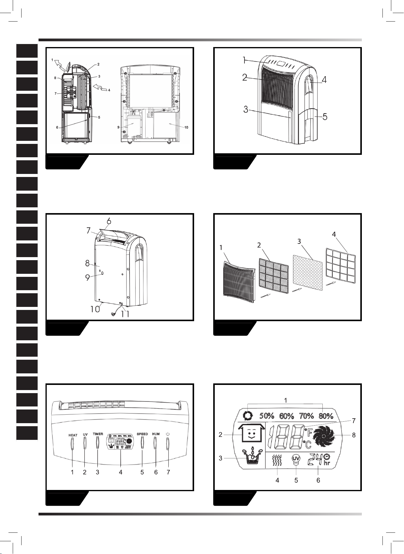
► Control panel FIG. 5
1. Heat button (only for the model with heat function)
2. UV light (only for the model with UV function)
3. Timer
4. Display window
5. Speed (ventilation) button
6. Humidity selection button
7. ON/OFF button
► Display window FIG. 6
1. Humidity display: continuous de-humidifying , 50%,
60%, 70%, 80%
2. Ambient humidity condition: good , fair , bad
means 50% ≤ambient room humidity ≤70%
means 30% ≤ambient room humidity < 50% or 70% <
ambient room humidity ≤80%
means the ambient room humidity is higher than
80%.
3. compressor is in progress. In case the de-frost func-
tion is working, the water drops will ash.
compressor is not in progress.
water full.
4. Heat indicator (only for the model with heat function):
While you press the heat button and the ambient tempera-
ture is lower than 25OC, the heat indicator will light on and
the heater will work. At this time, the fan speed will keep
at high speed only. However, if the ambient temperature is
higher than 25OC, the heat indicator will not light on and the
heater will not work, either. * This PTC heater is protected
by thermostat & thermal fuse for overheat protection.
5. UV ( ultraviolet ) indicator, only for the model with UV
light. * UV can kill the bacteria in the air.
6. Timer indicator, 1 to 24 hours.
7. Room temperature indicator, can display the room tem-
perature in Celsius degree (OC) by pressing “HUM” button
at least 2 seconds.
8. Fan speed/ventilation indicator: high speed, low
speed.
► Operation
1. Plug the unit into a correct mains socket. (Please refer to
the rating label at the rear of the unit.)
2. Press button ON/OFF to turn on the unit. The compres-
sor will start to work in continuous mode.
3. Press button HUMIDITY to set the room humidity you
need: continuous de-humidifying, 50%, 60%, 70% or 80%
4. Press the speed button to choose the ventilation speed,
high or low.
5. To turn off the unit, press button ON/OFF again.
6. The direction of the air outlet can be adjusted by hand.
►6. DRAINAGE
While the water tank is full, the compressor will stop for
self-protection and:
► The sign of water full will ash.
► The unit will buzz. * For stopping the buzz, you may
press the ON/OFF button to turn off the unit
► The water level display will turn into red.
To move the water tank, pull it out squarely from the unit by
using the handle at the water tank.
After empting the water tank, place the water tank into spa-
ce. Make sure it is properly positioned, in order for the ’wa-
ter full’ sign to go out and your dehumidier is operating.
Please note, in case, the water tank has not been positio-
ned well, the water level window will turn into red and the
unit will buzz, too.
To move the water tank, pull it out squarely from the unit by
using the handle at the water tank. (FIG. 8)
As the water tank is full or has not been positioned well, the
water level window will turn into red. (FIG. 9)
►CONTINUOUS DRAINAGE
When the dehumidier is operated at very high humidity
levels, the water tank will require more frequent drainage.
In this situation, it may be more convenient to set the unit
up for continuous drainage with the following procedures:
► Cut the outlet at the unit back. (FIG. 10A).
* CAUTION:
When the outlet is cut off, the said portion would leave as a
hole and cannot be covered by any plug.. If cover the said
portion by plug, the drainage water cannot go down to the
water tank.
► Connect the drain hole with a water tube of inner diame-
ter 12mm. (FIG. 10B)
* Please note, the water tube is not supplied with the unit.
Ensure the water will always drain away freely and the tube
will remain in place. Note! In very cold weather conditions,
precautions should be taken to prevent the water tube from
freeing.
Water tube of inner dia. 12 mm. Please note, the tube is
not supplied with the unit.
►7. MAINTENANCE
Always unplug the unit from the mains before carrying out
any maintenance or cleaning of the unit.
CLEANING THE BODY
Use soft cloth to wipe the unit clean.
Don’t ever use volatile chemicals, gasoline, detergents,
chemically treated clothes, or other cleansing solutions.
These all could possibly hurt the cabinet.
CLEANING THE FILTER
For washable lter - Use a vacuum cleaner or tap the lter
lightly for easy cleaning. If the lter is particularly dirty, use
warm water with a small amount of medium strength.
For active carbon lter - This lter is not washable. Its life
span is variable and depends on the ambient conditions
where the appliance is used. The lter should be checked
periodically (about every 6 months) and replaced if neces-
sary.
► FIG. 11
1. Filter xer
► FIG. 12
1. Grille
2. Washable lter
3. Active carbon lter
en
it
de
es
fr
nl
pt
da
no
sv
pl
ru
cs
hu
sl
hr
lt
lv
sk
SI
sk
bg
uk
SI
SK
TR
UA

4. Filter xer
STORAGE
If not use the unit for an extended period of time. Please:
Turing the unit off, unplug and tidy AC cord.
► Completely empty the water tank and wipe it clean.
► Cover the unit and store where it will not receive direct
sunlight.
►8. TROUBLE SHOOTING
THE UNIT DOES NOT OPERATE:
► Is the unit plugged in?
► Is the house electricity on?
► Is the room temperature below 5OC or above 35OC? If
so, then it is out of the working range of the unit.
► Ensure the humidistat (or ON/OFF switch) is turned on.
► Check the water tank is positioned properly in the unit
and it is not full.
► Make sure the air inlet and outlet are not obstructed.
THE UNIT SEEMS TO DO NOTHING:
► Is the lter dusty, contaminated ?
► Is the air intake or outlet blocked up?
► Is the room humidity already quite low?
THE UNIT SEEMS TO DO LITTLE:
► Are too many windows or doors open?
► Is there something in the room producing lots of humi-
dity?
THE UNIT IS TOO NOISY:
► Check whether the unit is sitting on a level surface.
THE UNIT IS LEAKING:
► Make sure the unit is in good shape.
► If you are not using continuous drainage, make sure
the rubber plug (at the bottom of the unit) is in its position.
en
it
de
es
fr
nl
pt
da
no
sv
pl
ru
cs
hu
sl
hr
lt
lv
et
ro
sk
bg
uk

en
it
de
es
fr
nl
pt
da
no
sv
pl
ru
cs
hu
sl
hr
lt
lv
sk
SI
sk
bg
uk
SI
SK
TR
UA

PRIMA DI USARE L’IMPIANTO BISOGNA LEG-
GERE ATTENTEMENTE L’ISTRUZIONE DI USO E
CONSERVARLA PER POTER CONSULTARLA IN
FUTURO.
►1. FUNZIONAMENTO
L’impianto serve alla deumidicazione dell’aria. Controlla
l’umidità relativa lasciando passare l’aria per l’impianto,
conducendo alla condensazione dell eccesso diumidità
sugli elementi refrigeranti. Il contatto con la supercie
fredda provoca la condensazione dell’umidità nell’aria. Poi
l’acqua condensata è tras messa al. contenitore dell’acqua.
Poi, l’aria secca passa per condensatore dove viene un po
riscaldata, e poi introdotta di nuovo nel locale, ma la sua
temperatura è adesso un po aumentata.
► FIG. 1
1. uscita l’aria secca,
2. condensatore,
3. evaporatore,
4. entrata l’aria umida,
5. microcommutatore,
6,10. contenitore acqua,
7. motore,
8. ventilatore,
9. compressore
►2. UBICAZIONE
l’eccesso di umidità andrà in tutta la casa, nello stesso
modo che si diffonde l’odore durante la cottura. per questo,
il deumidicatore deve avere il posto giusto per poter rac-
cogliere l’aria umida di tutta la casa.
Eventualmente se in un posto scopriamo il problema pos-
siamo mettere il deumidicatore nella sua vicinanza, e poi
spostarlo nel punto centrale.
Posizionando il deumidicatore, bis ogna assicurarsi che
Si trovi sul posto piatto e che da ogni parte dell’impianto ci
sono 10 cm (4”) di spazio libero per garantire usso libero
dell’aria.
il deumidicatore è dotato In ruote autoallineantesi per
garantira la mobilità migliore. Durante lo spostamento,
l’impianto deve esser spento, e il contenitore dell’acqua
svuotato.
Non consigliamo di usare la prolunga, quindi bisogna as-
sicurarsi che l’impianto si trovi abbastanza vicio alla presa
di corrente. quando l’uso della prolunga è inevitabile, biso-
gna assicurarsi che il dimatro dei li del cavo è di almeno
1 mm2.
Durante la deumidicazione, tutte le nestre e le porte de-
vono essere chiuse, per garantire il massimo rendimento
dell’impianto.
►3. CONSIGLI PRIMA DELL’USO
DELL’IMPIANTO
ATTENZIONE:
► Impianto deve trovarsi in posizione verticale.
► Dopo il tras porto oppure dopo esser inclinato (a.e. du-
rante la pulizia), l’impianto deve trovarsi per un ora in posi-
zione verticale prima di esser inserito all’alimentazione
► Tenere lontano da tutti i fori di entrata ed uscita dell’aria,
ogni corpo estraneo.
► Alimentazione elettrica deve essere conforme alla spe-
cicazione dal targhetto dati dell’impianto.
► Se il cavo di alimentazione è rotto, deve esser subito
sostituito dal personale autorizzato, per evitare il pericolo.
► Non si deve usare la spina elettrica per accendere o
spegnere l’impianto. Bisogna sempre usare il pulsante sul
pannello commando.
► Prima di spostare l’impianto si deve spegnerlo, e poi
svuotare il contenitore dell’acqua.
► Non usare l’aerosolo insetticida oppure altri detergenti
inammabili.
► E vietato di spruzzare o bagnare l’impianto
AVVERTENZE !
Non usare l’impianto nella temperatura ambientale infe-
riore a 50C, per evitare il gelo dell’evaporatore.
►4. PARTI
► Fronte FIG. 2
1. Pannello di commando
2. entrata d’aria / ltri
3. Finestra livello acqua
4. Mandrino
5. Contenitore dell’acqua
► Didietro FIG. 3
6. Coperchio dell’uscita d’aria
7. uscita d’aria
8. Pannello di dietro
9. Foro dello scolo continuo dell’acqua
10. Ruota
11. Cavo di alimentazione
►5. SERVIZIO
► Pannello di commando FIG. 4
1. Pulsante “Riscaldamento” (solo in modello con funzione
del riscaldamento)
INDICE
1... FUNZIONAMENTO
2... UBICAZIONE
3... CONSIGLI PRIMA DELL’USO DELL’IMPIANTO
4... PARTI
5... SERVIZIO
6... USCITA DELL’ACQUA
7... MANUTENZIONE E CONSERVAZIONE
8... RIVELAZIONE DEI DIFETTI
en
it
de
es
fr
nl
pt
da
no
sv
pl
ru
cs
hu
sl
hr
lt
lv
et
ro
sk
bg
uk

2. Luce ultravioleto (solo in modello con funzione della luce
ultravioleta)
3. TIMER
4. Visualizzatore
5. Pulsante della regolazione della velocità (ventilazione)
6. Pulsante dell’umidità
7. Pulsanti ON/OFF (ACCESO / SPENTO)
► Visualizzatore FIG. 5
Indicazioni
1. Dell’umidità Deumidicazione costante 50%, 60%,
70%, 80%.
2. Condizioni nel regime dell’umiditdell’ambiente: Buone
, sufcienti , cattive
Signica 50% ≤ umidità dell’ambiente ≤70%
Signica 30% ≤ umiditdell’ambiente < 50% lub 70% <
umidità dell’ambiente ≤80%
Signica che l’umidità dell’ambiente è superiore al
80%
3. Compressore lavora In caso della funzione di scong-
elamento attiva, le gocce di acqua comminciano a lampeg-
giare
Compressore non lavora.
Il contenitore è riempito di acqua.
4. Indicatore del calore (solo in modello con funzione del
riscaldamento): In momento di premere il pulsante del ris-
caldamento, se la temperatura ambientale sarà piu bassa
di 250C, l’indicatore del calore si accenderà e il riscalda-
mento commincera nzionare. In questo tempo, la velo-
cità del ventilatore sarà alta. Invece se la temperatura am-
bientale oltrepasserà 250C, l’indicatore del calore non si
accenderà ed il riscaldatore non funzionerà. * Il riscaldator
PTC è protetto contro il surriscaldamento con termostato &
congegno termico
5. Indice UV -( luce ultravioleto )solo in modello con fun-
zione della luce ultravioleta. * UV possono eliminare i bat-
teri nell’aria.
6. Indicatore TIMER da 1 a 24 ore
7. Indice della temperatura dell’ambiente visualizza la tem-
peratura ambientale in gradi C (0C) grazie di premere il
pulsante per almento 2 secondi.
8. Velocità del ventilatore / Indicatore della ventilazione:
Velocità altra velocità bassa.
► Servizio
1. Inserire l’impianto all’alimentazione adequata. (leg-
gere la targhetta dati che si trova nella parte posteriore
dell’impianto).
2. Premere pulsante ON/OFF per accendere l’impianto. Il
compressore commincerà il lavoro continuo.
3. Premere il pulsante HUMIDITY per addaattare l’umidità
desiderata. Deumidicazione continua: 50%, 60%, 70% o
80%
4. Premere il pulsante di regolazione della velocità per
scegliere la velocità di ventilazione adequata in regime da
alta a bassa.
5. Per spegnere l’impianto, bisogna premere di nuovo il
pulsante ON/OFF.
6. L’uscita dell’aria puó essere adattata manualmente.
►6. USCITA DELL’ACQUA
In momento del riempimento del contenitore acqua, il com-
pressore smetterà di lavorare nell’ambito del meccanismo
autoprotezione:
► Simbolo “contenitore pieno” commincerà a lam-
peggiare.
► I’impianto commincerà a ronzare. *Per eliminare il ron-
zio, bisogna premere il pulsante ON/OFF per spegnere
l’impianto.
► Visualizzatore del livello acqua diventerà rosso.
Per spostare il contenitore acqua, bis ogna estrarlo com-
pletamente dall’impianto, tramite il manico sul contenitore
acqua.
Dopo aver svuotato il contenitore, bisogna rimetterlo al
suo posto. Assicurarsi che sia posizionato bene, simbolo
„contenitore pieno” sparisce ed umidicatore commincia a
lavorare.
Se il contenitore non sarà ben posizionato, il visualizzatore
diventerà rosso subito ed impianto commincerà a ronzare.
Per spostare il contenitore acqua, bisogna estrarlo
dall’impianto tramite il manico che si trova sul contenitore
dell’acqua. (FIG. 8)
Se il recipiente è pieno oppure non è stato posizionato
bene, il visualizzatore del livello acqua diventerà rosso.
(FIG. 9)
SCOLLO CONTINUO
Se l’umidicatore lavora nell’umidità molto alta, l’acqua del
contenitore dovrà essere scaricata piu spesso. In questo
caso, è meglio addattare lo scollo continuo utilizzando i
procedimenti seguenti:
► Tagliare l’uscita in prossimità dell’impianto, (FIG. 10A).
* ATTENZIONE:
Quando l’uscita sarà tagliata, avremo il foro e non potremo
chiuderlo col tappo. Se sarà chiuso col tappo, l’acqua non
potrà mai essere scaricata al contenitore.
► Collegare il foro di scarico col tubo di acqua al diametro
interno di 12 mm. (FIG. 10B)
* Prendere in considerazione il fatto che il tubo non appar-
tiene all’attrezzatura dell’impianto.
Assicurarsi che l’acqua potrà sempre uscire liberamente
ed il tubo non cambierà posto. Attenzione! In caso delle
cattive condizioni atmosferiche, bisogna pensare alle con-
dizioni di sicurezza speciali per non lasciare congelare il
tubo.
►7. MANUTENZIONE E CONSERVAZIONE
Prima di comminciare la manutenzione o la pulizia bisogna
scollegare l’impianto dalla rete elettrica.
PULIZIA DELLA CARCASSA
Per pulire l’impianto bis ogna usare il tessuto morbido.
Vietato di usare delle sostanze chimiche voltatili, detergen-
ti, benzina, vestiti trattati chimicamente, pure altrie soluzio-
ni di pulizia. Ogni sostanza sopra citata puó danneggiare la
carcassa dell’impianto.
PULIZIA DEL FILTRO
In caso del ltro lavabile - usare l’aspirapolvere oppure
picchiare legermente il ltro per pulirlo. Se il ltro è molto
sporco, usare dell’acqua calda con una piccola quantità del
en
it
de
es
fr
nl
pt
da
no
sv
pl
ru
cs
hu
sl
hr
lt
lv
sk
SI
sk
bg
uk
SI
SK
TR
UA

detergente debole.
Il ltro con carbone attivato non è lavabile. La sua vita-
lità e diversa e dipende dalle condizioni ambientali in cui
l’impianto lavora. Il ltro deve esser ispezionato periodica-
mente (ogni 6 mesi) ed in caso di necessita deve esser
cambiato.
► FIG. 11
1. Fissaggio del ltro
► FIG. 12
1. Graglia
2. Filto lavabile
3. Filtro col carbone attivato
4. Fissaggio del ltro
CONSERVAZIONE:
Se l’impianto non è usato per lungo tempo bisogna speg-
nerlo. Filo di allimentazione deve esser scollegato e pulito:
► Svuotare completamente il contenitore acqua ed asci-
ugarlo con cura.
► Coprire l’impianto per protteggerlo contro i raggi del
sole.
►8. RIVELAZIONE DEI DIFETTI
IMPIANTO NON FUNZIONA:
► Impianto non collegato alla rete elettrica?
► Rete elettrica a casa è accesa?
► Temperatura ambientale è di 50C oppure piu di 350C?
Rispondendo si alle domande, sappiamo che la tempera-
tura è fuori il regime di lavoro dell’impianto.
► Bisogna assicurarsi se umidostato (oppure commuta-
tore ON/OFF) sià acceso.
► Controlare se il contenitore acqua sia posizionato cor-
rettamente nell’impianto e se non sia pieno.
► Assicurarsi che l’entrata e l’uscita dell’aria non siano
bloccate.
IMPIANTO SEMBRA NON LAVORARE:
► Filtro è sporco ?
► Entrata ed uscita sono bloccate?
► Umidita nel locale non è troppo bassa?
LAVORO DELL’IMPIANTO SEMBRA ESSER INEF-
FICIENTE:
► Troppe porte e nestre aperte?
► Nel locale funziona l’impianto che genera troppa umi-
dita?
IMPIANTO E TROPPO RUMOROSO:
► Controlare se l’impianto sia stabile sulla supercie pi-
atta.
IMPIANTO PERDE:
► Assicurarsi che stato tecnico dell’impianto sia buono
► Se lo scollo continuo dell’acqua non è usato, biso-
gna assicurarsi che il tappo di gomma (parte inferiore
dell’impianto) sia ben posizionato.
en
it
de
es
fr
nl
pt
da
no
sv
pl
ru
cs
hu
sl
hr
lt
lv
et
ro
sk
bg
uk

en
it
de
es
fr
nl
pt
da
no
sv
pl
ru
cs
hu
sl
hr
lt
lv
sk
SI
sk
bg
uk
SI
SK
TR
UA

VOR DER ANWENDUNG DIESES GERÄTES SOLL
MAN SICH AUSFÜHRLICH MIT DER ANLEITUNG
BEFASSEN UND SIE DANN AUFBEWAHREN UM
SPÄTER NUTZEN ZU KÖNNEN.
►1. FUNKTIONSWEISE
Das vorliegende Produkt dient zum Trockenen von Luft.
Es überwacht die relative Feuchtigkeit indem es die Luft
durch das Gerät verarbeitet und zur Kondensierung des
Übermaßes an Feuchtigkeit an den Kälteteilen führt. Die
Berührung mit kalter Oberache bewirkt, dass sich die
Feuchtigkeit in der Luft verüssigt. Danach wird das Kon-
denswasser sicher in den Wasserbehälter abgeleitet. Die
getrocknete Luft geht durch den Kondensator, in dem sie
leicht erwärmt wird und dann wieder in den Raum eing-
espeist wird, wobei ihre Temperatur ist gering erhöht.
► FIG. 1
1. TROCKNE WÄRMERE LUFT,
2. KONDENSATOR,
3. VERDAMPFER – kalte Rohren,
4. MIT FEUCHTIGKEIT GESÄTTIGTE LUFT,
5. MIKROSCHALTER,
6,10. WASSERBE-HÄLTER,
7. MOTOR,
8. VENTILATOR,
9. KOMPRESSOR,
►2. PLATZIERUNG
Das Übermaß an Feuchtigkeit wird sich im ganzen Haus
verteilen auf die selbe Art und Weise wie sich Gerüche wäh-
rend des Kochens im ganzen Raum ausbreiten. Deswegen
sollte die Trocknungsanlage so platziert werden, dass er
feuchte Luft aus dem ganzen Haus aufnehmen kann.
Es besteht auch die Möglichkeit, dass, wenn an einer Stel-
le im Haus es zu einem ernsthaften Problem kommt, man
die Trocknungsanlage in der Nähe dieser Stelle stellt und
danach sie in einen mehr zentralen Punkt verschiebt.
Während die Trocknungsanlage aufgestellt wird, soll man
sich vergewissern, dass sie sich auf ebener Fläche ben-
det und, ob an jeder Seite 10 cm (4“) Freiraum vorhanden
sind, um einen leistungsfähigen Luftuss zu ermöglichen.
Diese Trocknungsanlage ist mit Rädern ausgestattet, um
ihm bessere Bewegungsfreiheit zu garantieren. Wenn
das Gerät verschoben werden soll, muss man es vorher
ausschalten und den Wasserbehälter entleeren.
Es wird nicht empfohlen einen Verlängerungskabel zu
benutzen, im Zusammenhang damit soll man sich ver-
gewissern, ob das Gerät sich ausreichend Nah an einer
Steckdose bendet. Wenn die Verwendung eines Verläng-
erungskabels notwendig sein wird, muss man sich ver-
gewissern, ob der Kabeldurchmesser mindestens 1 mm2
beträgt.
Während das Gerät arbeitet, sollten bei Notwendigkeit die
Außentüren und Fenster geschlossen bleiben, und die
maximale Leistungsfähigkeit des Gerätes zu sichern.
►3. EMPFEHLUNGEN VOR DEM ERSTBE-
TRIEB
ACHTUNG!
► Das Gerät muss immer in vertikaler Stellung aufgestellt
sein.
► Das Gerät muss sich vor dem Anschließen ans Ver-
sorgungsnetz eine Stunde lang in vertikaler Stellung ben-
den, nachdem es transportiert oder geneigt (z.B. bei der
Reinigung) wurde.
► Alle Fremdkörper solle weit von den Ein- und Ausgang-
söffnungen aufbewahrt werden.
► Die Stromversorgung muss mit der Nenntafel übereins-
timmen, die sich auf der Rückseite des Gerätes bendet.
► Wenn der Versorgungskabel beschädigt ist, muss er
vom autorisierten Fachhändler unserer Serviceabteilung
oder einer Person, die über entsprechende Befugnisse
verfügt, ausgetauscht werden, damit es zu keine Gefahr
kommt.
► Zum Ein- und Ausschalten darf man in keinem Fall den
Stecker benutzten. Man muss immer den Schalter auf dem
Bedienungsfeld benutzten.
► Bevor das Gerät verstellt oder verschoben wird, muss
man es erst ausschalten und den Wasserbehälter entle-
eren.
► Man darf keine Sprühsubstanzen gegen Insekten oder
andere leichtbrennbare Reinigungsmittel verwenden.
► In keinem Fall darf man das Gerät mit Wasser besprüh-
en oder begießen.
WICHTIG!
Das Gerät darf man nicht einsetzen, wenn die Raumtem-
peratur unter 5°C fällt, damit es nicht zum Vereisen des
Verdampferschlauches kommt.
►4. TEILE
► Vorderseite FIG. 2
1. Bedienungsfeld
2. Lufteinlassöffnung / Filter
3. Regulierungsfenster des Wasserniveaus
4. Griff
5. Wasserbehälter
BEDIENUNGSANLEITUNG
1... FUNKTIONSWEISE
2... PLATZIERUNG
3... EMPFEHLUNGEN VOR DEM ERSTBETRIEB
4... TEILE
5... BEDIENUNG
6... WASSERABLEITUNG
7... WARTUNG UND INSTANDHALTUNG
8... MÄNGELERKENNUNG
en
it
de
es
fr
nl
pt
da
no
sv
pl
ru
cs
hu
sl
hr
lt
lv
et
ro
sk
bg
uk

► Rückseite FIG. 3
6. Luftauslassöffnungsdeckel
7. Luftauslassöffnung
8. Rückseitenplatte
9. Öffnung der ständigen Wasserableitung
10. Rad
11. Versorgungskabel
► Filtermontage FIG. 4
1. Gitter
2. Abwaschbarer Filter
3. Aktivkohlelter
4. Filterbefestigung
►5. BEDIENUNG
► Bedienungsfeld FIG. 5
1. Heiz-Taste (ausschließlich für das Model mit der Heiz-
funktion)
2. Ultraviolett-Licht(ausschließlich für das Model mit der
Funktion des Ultraviolettlichts)
3. Zeitmessgerät
4. Display
5. Taste der Geschwindigkeitsregulierung (Lüftung)
6. Teste der Feuchtigkeitswahl
7. ON/OFF-Taste (Ein-/Ausschalten)
► Display FIG. 6
1. Feuchtigkeitsanzeige: ständiges Trocknen, 50%,
60%, 70%, 80%
2. Bedingungen bezüglich der Umgebungsfeuchtigkeit: gut
, ausreichend , schlecht .
bedeutet 50% ≤ Umgebungsfeuchtigkeit ≤70%
bedeutet 30% ≤ Umgebungsfeuchtigkeit < 50% oder
70% < Umgebungsfeuchtigkeit ≤80%
bedeutet, dass die Umgebungsfeuchtigkeit höher ist
als 80%.
3. der Kompressor arbeitet gerade. Im Fall, wenn die
Entfrostungsfunktion aktiv ist, werden die Wassertropfen
anfangen zu blinken.
der Kompressor arbeitet nicht.
der Behälter ist mit Wasser befüllt.
4. Die Wärmeanzeige (ausschließlich für das Model mit der
Heizfunktion): wenn man die Heiztaste drückt, wenn die
Umgebungstemperatur niedriger sein wird als 25oC, wird
die Wärmeanzeigeaueuchten und der Erhitzer nimmt
seine arbeit auf. In diesem Zeitraum wird die Geschwin-
digkeit des Ventilators auf hohem Niveau bleiben. Doch,
wenn die Umgebungstemperatur höher sein wird als 25°C,
wird die Wärmeanzeige leuchten und der Erhitzer wird sich
ausschalten. * Dieser PTC-Erhitzer wird mit einem Ther-
mostat und einer Thermosicherung vor dem Überhitzen
geschützt.
5. UV-Anzeige (Ultraviolettstrahlen), ausschließlich für das
Model mit der Funktion des Ultraviolettlichts. * Das UV-
Licht kann Bakterien in der Luft beseitigen.
6. Zeitmessanzeige, 1 bis 24 Stunden.
7. Umgebungstemperaturanzeige kann die Umgebungs-
temperatur in der Celsiusskala (°C) dank dem Drücken der
Taste “HUM“ für mindestens 2 Sekunden.
8. Ventilatorgeschwindigkeit/Lüftungsanzeige: hohe
Geschwindigkeit, niedrige Geschwindigkeit.
Bedienung
1. Das Gerät an die entsprechende Stromversorgung an-
schließen. (siehe Nenntefel auf der Geräterückseite).
2. Die ON/OFF-Taste drücken, um das Gerät einzuschal-
ten. Der Kompressor wird seine Arbeit im Dauermodus be-
ginnen.
3. Die Taste HUMIDITY drücken, um die geforderte Feuch-
tigkeit anzupassen: ständiges Trocknen: 50%, 60%, 70%
oder 80%
4. Die Geschwindigkeitsregulierungstaste drücken, um die
Lüftungsgeschwindigkeit (im Bereich: Hoch bis Niedrig)
auszuwählen.
5. Um das Gerät auszuschalten, soll man wieder die ON/
OFF-Taste drücken.
6. Die Luftausblasrichtung kann man manuell anpasse.
(FIG. 7)
►6. WASSERABLEITUNG
Wenn der Wasserbehälter befüllt wird, wird der Kompres-
sor aufhören im Rahmen des Selbstschutzmechanismus’
zu arbeiten:
► Das Zeichen „Behälter voll“ fängt an zu blinken.
► Das Gerät fängt an zu summen. * Um das Summen zu
beseitigen, kann man die ON/OFF-Taste drücken und das
Gerät schaltet ab.
► Die Wasserstandanzeige wird ihre Farbe auf Rot än-
dern.
Um den Wasserbehälter zu verschieben, muss man ihn
vollständig aus dem Gerät rausnehmen, was man mit Hilfe
des auf dem Behälter befestigten Griffes macht. Nach dem
Entleeren des Wasserbehälters, soll man ihn an richtiger
Stelle platzieren. Man muss sich dabei vergewissern, dass
er ordnungsgemäß aufgestellt wurde, damit das Zeichen
„Behälter voll“ verschwindet und die Trockenanlagen an-
fängt zu funktionieren.
Bitte berücksichtigen Sie, dass im Fall, wenn der Wasser-
behälter nicht ordnungsgemäß aufgestellt wird, die Was-
serniveauanzeige seine Farbe auf Rot verändern wird, das
Gerät wird hingegen anfangen zu summen.
Um den Wasserbehälter zu verschieben, muss man ihn
aus dem Gerät rausnehmen, was man mit Hilfe des auf
dem Behälter befestigten Griffes macht. (FIG. 8)
Wenn der Behälter mit Wasser voll ist oder falsch aufges-
tellt wurde, ändert die Wasserniveauanzeige ihre Farbe
auf rot. (FIG. 9)
STÄNDIGE ABLEITUNG
Wenn die Trockenanlage bei sehr hohen Feuchtigkeitsni-
veaus arbeitet, wird das Wasser aus dem Behälter öfter
abgeleitet werden. In dieser Situation, kann die Anpassung
des Gerätes an die ständige Wasserableitung lohnenswert
sein. Dabei hilft es Ihnen, wenn Sie wie folgt verfahren:
► Den Abuss am Gerät abtrennen. (FIG.10A).
en
it
de
es
fr
nl
pt
da
no
sv
pl
ru
cs
hu
sl
hr
lt
lv
sk
SI
sk
bg
uk
SI
SK
TR
UA

* ANMERKUNG:
Wenn der Abuss abgetrennt wird, bleibt der erwähnte Teil
als eine Öffnung und diese wird nicht mit einer Blende ver-
stopft werden. Wenn der erwähnte Teil mit einer Blende
verstopft wird, dann kommt es dazu, dass das Wasser
nicht in den Behälter abgeleitet werden kann.
► Die Auslassöffnung an ein Wasserrohr mit einem Innen-
durchmesser von 12 mm anschließen. (FIG. 10B)
* Man muss es berücksichtigen, dass das Rohr keine Aus-
stattung des Gerätes ist.
Sich vergewissern, ob das Wasser immer frei abgeleitet
werden kann und das Rohr an ihrer Stelle bleibt. Achtung!
Im Fall, wenn die atmosphärischen Bedingungen schlecht
sein werden, muss man Schutzmaßnahmen vornehmen,
um das Vereisen des Wasserrohrs zu verhindern.
Wasserrohr mit Innendurchmesser 12 mm. Man muss es
berücksichtigen, dass das Rohr keine Ausstattung des Ge-
rätes ist.
►7. WARTUNG UND INSTANDHALTUNG
Bevor Wartungs- oder Reinigungsarbeiten am Gerät vor-
genommen werden, soll man es immer von der Stromver-
sorgung trennen.
GEHÄUSEREINIGUNG
Um das Gerät zu reinigen, soll man einen weichen Lappen
verwenden.
In keinem Fall darf man chemische Sprühsubstanzen,
Detergentien, Benzin, Kleidung, die chemisch verarbeitet
wurde, oder andere Reinigungslösungen verwenden. Jede
dieser Substanzen kann das Gehäuse beschädigen.
FILTERREINIGUNG
Im Fall eines abwaschbaren Filters – soll man einen Stau-
bsauger verwenden oder den Filter leicht abstauben, um
ihn dann leicht reinigen zu können. Wenn der Filter stark
verunreinigt ist, soll man warmes Wasser mit einer gering-
en Menge einer mittelstarken Substanz verwenden.
Wenn es um den aktiven Kohlelter geht, dieser ist ab-
waschbar. Seine Haltbarkeit ist veränderbar und hängt
von den Umgebungsbedingungen ab, in denen das Gerät
benutzt wird. Der Filter sollte einer zwischenzeitlichen Dur-
chsicht unterzogen werden (mindestens jede 6. Monate)
und wen dies notwendig sein wird, muss man ihn austau-
schen.
► FIG. 11
1. Filterbefestigung
► FIG. 12
1. Gitter
2. Abwaschbarer Filter
3. Aktivkohlelter
4. Filterbefestigung
AUFBEWAHRUNG
Wenn das Gerät eine länger Zeitlang nicht benutzt wird,
soll man es ausschalten. Den Stromversorgungskabel soll
man abschalten und reinigen:
► Man soll vollständig den Wasserbehälter entleeren und
ihn abwischen.
► Das Gerät soll man abdecken und an einem Ort aufbe-
wahren, wo es keinen Sonnenstrahlen ausgesetzt wird.
►8. MÄNGELERKENNUNG
DAS GERÄT FUNKTIONIERT NICHT:
► Ist das Gerät an das Stromnetz angeschlossen?
► Ist die Elektrizität im Haus eingeschaltet?
► Beträgt die Raumtemperatur 5°C oder mehr als 35°C?
Wenn ja, dann liegt sie außerhalb des Arbeitsbereichs des
Gerätes.
► Man soll sich vergewissern, ob das Humidostat (oder
die ON/OFF-Taste) eingeschaltet ist.
► Man soll überprüfen, ob der Wasserbehälter ordnungs-
gemäß im Gerät eingebaut ist und ob er nicht voll ist.
► Man soll sich vergewissern, ob die Luftein- und Luftaus-
lassöffnungen nicht gesperrt sind.
ES SCHEINT, DASS DAS GERÄT NICHT ARBEI-
TET:
► Ist der Filter verunreinigt oder verstaubt?
► Ist die Lufteinlass- oder Luftauslassöffnung blockiert?
► Ist die Umgebungsluftfeuchtigkeit nicht schon zu
niedrig?
ES SIEHT SO AUS ALSOB DAS GERÄT UNPRO-
DUKTIV ARBEITEN WÜRDE:
► Sind zu viele Fenster oder Türen geöffnet?
► Bendet sich im Raum irgendetwas, was hohe Feuch-
tigkeit verursacht?
DAS GERÄT IST ZU LAUT:
► Man muss überprüfen ob das Gerät auf gerader Fläche
steht.
DAS GERÄT HAT EINEN LECK:
► Man soll sich vergewissern, ob das Gerät im guten
technischen Zustand ist.
► Wenn der Modus der ständigen Wasserableitung nicht
genutzt wird, soll man sich vergewissern ob die Gummi-
blende (unten am Gerät) in ihrem Platz ist.
en
it
de
es
fr
nl
pt
da
no
sv
pl
ru
cs
hu
sl
hr
lt
lv
et
ro
sk
bg
uk

en
it
de
es
fr
nl
pt
da
no
sv
pl
ru
cs
hu
sl
hr
lt
lv
sk
SI
sk
bg
uk
SI
SK
TR
UA

Antes de utilizar este aparato hay que leer detenidamente
el manual de instrucciones y guardarla para sus futuras
consultas.
►1. FUNCIONAMIENTO
Este producto está destinado a deshumidicar el aire. Con-
trola la humedad relativa al pasar el aire por el aparato,
provoca la condensación del exceso de la humedad en los
elementos refrigeradores. El contacto con una supercie
fría provoca la condensación de la humedad en el aire.
Seguidamente el agua condensada se conduce de forma
segura hacia el depósito de agua. El aire deshumidicado
pasa por el condensador donde se calienta ligeramente y
seguidamente queda expulsado y la temperatura del am-
biente sube ligeramente.
► FIG. 1
1. salida del aire seco,
2. condensador,
3. evaporador, 4. entrada del aire húmedo,
5. micro interruptor,
6,10. depósito de agua,
7. motor,
8. ventilador,
9. compresor
►2. UBICACIÓN
El exceso de humedad va a extenderse por toda la casa
del mismo modo que lo hace el olor cuando estamos co-
cinando. Por este motivo el deshumidicador debería ser
ubicado de manera que pueda absorber el aire húmedo de
toda la casa. Como excepción, si en un lugar determinado
aparece un problema grave, podemos acercar el deshumi-
dicador al dicho lugar y más tarde desplazarlo a un punto
más central de la casa.
Cuando estemos ubicando el deshumidicador tenemos
que asegurarnos de que este se encuentra en una super-
cie plana y tenga alrededor un espacio de 10 cm (4”) libres
para facilitar un ujo ecaz de aire. Este deshumidicador
tiene unas ruedas auto ajustables que le dan una mejor
movilidad. Antes de desplazar el aparato hay que apagarlo
y vaciar el depósito de agua.
No se aconseja el uso de un alargador. Por eso hay que
asegurarse de que el aparato se encuentra suciente-
mente cerca de un enchufe. En el caso de que el uso del
un alargador fuera necesario hay que asegurarse de que
el diámetro de los cables es de 1 mm2 como mínimo. A
medida de lo posible, mientras el deshumidicador esté
funcionando es aconsejable mantener las puertas y las
ventanas cerradas para asegurar de esta manera la mayor
ecacia del aparato.
►3. RECOMENDACIONES ANTES DE LA UTI-
LIZACIÓN
¡ATENCIÓN!
► El aparato tiene que estar en la posición vertical.
► Después de haber transportado el aparato o haberlo
dejado inclinado (p.ej. durante su limpieza) hay que dejarlo
en la posición vertical durante una hora antes de enchu-
farlo a la corriente eléctrica.
► No introduzca los dedos u objetos en la entrada y salida
del aire.
► La fuente alimentadora tiene que coincidir con la espe-
cicación indicada en la placa nominal de la parte trasera
del aparato.
► Si el cable o la clavija están dañados hay que sustitu-
irlos por una persona autorizada del servicio técnico (una
persona debidamente cualicada) para evitar situaciones
de riesgo.
► Para encender y apagar el aparato no se debe utilizar
la clavija. Siempre hay que utilizar el interruptor del panel
de control.
► Antes de desplazar el aparato hay que apagarlo y va-
ciar el depósito de agua.
► No utilice insecticidas ni otros detergentes limpiadores
inamables.
► Bajo ningún concepto eche agua encima del aparato.
IMPORTANTE!
No se debe utilizar el aparato en la temperatura del am-
biente más baja que 5OC, para evitar el del evaporador se
cubra de escarcha.
►4. COMPONENTES
► Frente FIG. 2
1. Panel de control
2. Entrada de aire / Filtros
3. Ventana de nivel de agua
4. Asa
5. Depósito de agua
► Atrás FIG. 3
6. Carcasa de la salida de aire
7. Salida de aire
8. Placa trasera
9. Oricio de salida continua de agua
10. Rueda
11. Cable alimentador
INDICE
1... FUNCIONAMIENTO
2... UBICACIÓN
3... RECOMENDACIONES ANTES DE LA UTILIZACIÓN
4... COMPONENTES
5... COMO MANEJARLO
6... ELIMINACIÓN DEL AGUA ALMACENADA
7... LIMPIEZA Y MANTENIMIENTO
8... DIAGNOSTICAR LOS PROBLEMAS
en
it
de
es
fr
nl
pt
da
no
sv
pl
ru
cs
hu
sl
hr
lt
lv
et
ro
sk
bg
uk

► Instalación de ltros FIG. 4
1. Parrilla
2. Filtro lavable
3. Filtro de carbono activo
4. Fijación del ltro
►5. COMO MANEJARLO
► Panel de control FIG. 5
1. El botón ”Calefacción” (únicamente en el modelo con la
función de calefacción)
2. Luz ultravioleta (únicamente en el modelo con la función
de luz ultravioleta)
3. TIMER / TEMPORIZADOR
4. Visualizador
5. Botón de regulación de velocidad (ventilación)
6. Botón de elección de la humedad
7. Botón ON/OFF (Encender/Apagar)
► Visualizador FIG. 6
Indicaciones
1. Humedad: deshumidicación continua 50%, 60%,
70%, 80%
2. Condiciones en el campo de la humedad del ambiente:
buenas sucientes , malas
indica 50% ≤de la humedad del ambiente ≤70%
indica 30% ≤ de la humedad del ambiente < 50% o
70% < de la humedad del ambiente ≤80%
indica que la humedad del ambiente supera 80%.
3. el compresor está funcionando. En el caso de que
esté activada la función de descongelación las gotas de
agua empiezan a parpadear.
el compresor no está funcionando.
el depósito de agua está lleno.
4. El indicador de calor (únicamente en el modelo con la
función de calefacción): Si en el momento de pulsar el
botón de calefacción la temperatura del ambiente es in-
ferior a los 25OC, el indicador de calor se encenderá y el
radiador empezará a funcionar. Durante ese tiempo la ve-
locidad del ventilador se mantendrá en un nivel alto. Sin
embargo, si la temperatura del ambiente es superior a los
25OC, el indicador de calor no se encenderá y el radiador
no va a funcionar. *Este radiador PTC está protegido con
un termóstato y un fusil térmico para evitar el sobrecalen-
tamiento.
5. El indicador UV (de la radiación ultravioleta), únicamente
en el modelo con la función de luz ultravioleta. * UV puede
eliminar del aire las bacterias.
6. El indicador TIMER / TEMPORIZADOR’desde 1 hasta
24 horas.
7. El indicador de temperatura del ambiente puede visua-
lizar la temperatura del ambiente en grados centígrados
(OC) gracias al botón “HUM” pulsado por lo menos durante
2 segundos.
8. La velocidad del ventilador/Indicador de la ventilación:
velocidad alta, velocidad baja.
► Para utilizar el deshumidicador
1. Enchufar el cable del aparato en la toma adecuada (ver
la placa nominal en la parte trasera del aparato.)
2. Pulsar el botón ON/OFF, para encender el aparato. El
compresor empezará a funcionar en le modo continuo.
3. Pulsar el botón HUMIDITY para ajustar la humedad de-
seada: la deshumidicación continua: 50%, 60%, 70% o
80%
4. Pulsar el botón de la regulación de la velocidad para
ajustar la velocidad de la ventilación en su campo desde
alta hasta baja.
5. Para apagar el aparato pulsar otra vez el botón ON/OFF.
6. La dirección de la salida de aire se puede regular manu-
almente. (FIG. 7)
►6. ELIMINACIÓN DEL AGUA ALMACENADA
Cuando el depósito de agua se llene el compresor dejará
de funcionar debido a su mecanismo de autoprotección:
► La señal „depósito lleno” empezará a parpadear.
► Se oirá un zumbido. * Para detener el zumbido se
puede pulsar el botón ON/OFF, para apagar el aparato
► El visualizador del nivel de agua cambiará de color y se
volverá rojo.
Para desplazar el depósito de agua hay que sacarlo to-
talmente del aparato con la ayuda del asa ubicada en el
depósito.
Una vez vaciado el depósito de agua tenemos que colo-
carlo en su sitio. Al mismo momento hay que asegurarse
de que este está colocado correctamente, para que la
señal de „depósito lleno” desaparezca y el deshumidica-
dor empiece a funcionar.
Se ruega tener en cuenta el hecho de que si el depósito de
agua no se coloque correctamente el visualizador del nivel
de agua se volverá rojo y se oirá un zumbido.
Para desplazar el depósito de agua hay que sacarlo
del aparato con la ayuda del asa ubicada en el depósito.
(FIG. 8)
Si el depósito de agua está lleno o no está colocado cor-
rectamente, el visualizador del nivel de agua se volverá
rojo. (FIG. 9)
VACIADO CONTINUO
Si los niveles de humedad alcanzan valores muy altos ha-
brá que vaciar más a menudo el agua del depósito. En
este caso puede resultar cómodo adaptar el aparato a la
salida continua de agua utilizando los siguientes procedi-
mientos:
► Cortar el extremo del oricio del drenaje del aparato.
(FIG. 10A).
* ¡ATENCIÓN!:
Si se corta el extremo del oricio del drenaje el dicho ele-
mento se convertirá en un agujero y no se podrá tapar con
un tapón.
Si el elemento mencionado se cierra con un tapón el agua
no podrá conducirse hacia el depósito.
► Conectar al agujero de desagüe un tubo de agua de
diámetro interior de 12mm. (FIG. 10B)
* Hay que tener en cuenta que el tubo no forma parte del
equipamiento del aparato.
Asegurarse de que el agua siempre pueda salir de forma
uida y el tubo se quede en su sitio. ¡Atención! En el caso
de malas condiciones atmosféricas hay que tomar las
medidas de precaución para evitar que el tubo de agua
se congele.
El tubo de agua de diámetro interior de 12 mm. Hay que te-
ner en cuenta que el tubo no forma parte del equipamiento
en
it
de
es
fr
nl
pt
da
no
sv
pl
ru
cs
hu
sl
hr
lt
lv
sk
SI
sk
bg
uk
SI
SK
TR
UA

del aparato.
►7. LIMPIEZA Y MANTENIMIENTO
Antes de empezar las labores de limpieza o mantenimien-
to hay que desconectar el aparato de la red eléctrica.
LIMPIEZA EXTERIOR
Usar un paño suave para limpiar el aparato.
Bajo ningún concepto use sprays, detergentes, gasolina,
ropa tratada con productos químicos u otras sustancias
limpiadoras. Cualquiera de las sustancias mencionadas
puede dañar la caja del aparato.
LIMPIEZA DEL FILTRO
En el caso de un ltro lavable se recomienda el uso de
una aspiradora o sacudir suavemente el ltro con el n de
limpiarlo más fácilmente. Si el ltro está muy sucio hay que
utilizar el agua caliente con una pequeña cantidad de un
detergente suave.
El ltro de carbón activo no es lavable. Su durabilidad es
variable y depende de las condiciones del ambiente donde
se usa el aparato. Hace falta pasar el control del servicio
técnico (aproximadamente cada 6 meses) y en el caso de
necesidad cambiarlo.
► FIG. 11
1. Fijación del ltro
► FIG. 12
1. Parrilla
2. Filtro lavable
3. Filtro de carbono activo
4. Fijación del ltro
ALMACENAMIENTO
Si el aparato no se utiliza durante una temporada se re-
comienda apagarlo. Se debe desenchufar el cable y lim-
piarlo:
► Es necesario vaciar completamente el depósito de
agua y secarlo.
► A continuación tapamos el aparato y lo guardamos en
un lugar donde no esté expuesto a rayos de sol.
►8. DIAGNOSTICAR LOS PROBLEMAS
EL APARATO NO ARRANCA:
► ¿El cable de alimentación está desenchufado?
► ¿La corriente eléctrica en casa está cortada?
► ¿La temperatura de la habitación es más baja que 5OC
o más alta que 35OC? Si es así la temperatura está fuera
de la temperatura de servicio.
► Asegurarse de que el humidostato (o el interruptor ON/
OFF) está encendido.
► Vericar si el depósito de agua está colocado correcta-
mente en el aparato y si está lleno.
► Asegurarse de que la salida y la entrada de aire no
están bloqueadas.
EL APARATO PARECE QUE NO FUNCIONA:
► ¿El ltro está sucio o con polvo?
► ¿La salida y la entrada de aire están bloqueadas?
► ¿La humedad del ambiente está ya demasiado baja?
EL APARATO PARECE QUE NO FUNCIONA EFI-
CAZMENTE:
► ¿Hay demasiadas puertas y ventanas abiertas?
► ¿Hay algo en la habitación que sube el nivel de hu-
medad?
EL APARATO ES DEMASIADO RUIDOSO:
► Vericar si el aparato está apoyado en una supercie
lisa.
EL APARATO PIERDE AGUA:
► Asegurarse de que el aparato está en buena condición
técnica.
► Si la opción de la salida continua de agua no está en
uso, hay que asegurarse de que el tapón de goma (que se
encuentra en la parte inferior del aparato) está en su sitio.
en
it
de
es
fr
nl
pt
da
no
sv
pl
ru
cs
hu
sl
hr
lt
lv
et
ro
sk
bg
uk

en
it
de
es
fr
nl
pt
da
no
sv
pl
ru
cs
hu
sl
hr
lt
lv
sk
SI
sk
bg
uk
SI
SK
TR
UA
Other manuals for DH-720
2
Table of contents
Languages:
Other Master Dehumidifier manuals