Mindeo FS580 User manual

FS580 Industrial Fixed Laser Barcode Scanner
User Manual
Version: FS580_UM_EN_V1.1.6


i
Notice
Make sure you carefully read the following information to ensure that your barcode scanner is able to
perform at the designed level.
1. All software, including firmware, furnished to the user is on a licensed basis.
2. The right is reserved to make changes to any software or product to improve reliability, function, or
design.
3. The material in this manual is subject to change without notice. Please go to www.mindeo.cn for
latest service information.
4. The manufacturer assumes no responsibility for any loss or claim by third parties which may arise
from the use of this manual.
5. Do not throw or drop the scanner or subject it to strong impact. Otherwise that can damage the
scanner, interrupt program execution, corrupt memory contents, or interfere with proper operation.
6. Please do keep exit window clean, otherwise it may cause that the scanner decodes incorrectly or
fails to read the barcode.

ii
Notes about structure and electric circuit design
1. Use non-magnetic screws, or locating pins when mounting the scanner. Magnetic screws or locating
pins can cause element/mirror central position to change.
2. It is recommended to use a thread locking method, such as a Nylok patch.
3. It is not recommended to place magnetic material (e.g. dynamic speakers, ringers, vibrators,
inductors, metal parts) within 1 inch of the scanner’s optics. Evaluate placement of all magnetic or
ferrous material during system layout to determine if 1 inch is sufficient. Please read section
“3-1
Important notes of installation”
for detail.
4. Leave sufficient space to accommodate the maximum size of the scanner.
5. Read section
“2-1 Electrical interface/Pin assignment”
carefully to learn about the electrical interface
design.
6. Read section
“2-2 Power management”
carefully to learn about the two power states.
7. Read section
“3-4 Scan angle”
carefully to learn about the scan angle of the scanner.
8. Do not hold the scanner vertically over the bar code. Please refer to section
“3-5 Tilt angle and dead
zone”
for details.
9. Refer to section
“5-13 PARAM_SEND”
, be noted that frequent permanent changes of parameter
value are not recommended due to the limited write-cycles of flash memory. It is recommended to
change parameter temporarily, if frequently modifying parameter is a must.
10. Read section
“6-4 SCI transactions notes”
carefully.

iii
Contents
Notice......................................................................................................................................................i
Notes about structure and electric circuit design.....................................................................................ii
1 Specifications ..................................................................................................................................... 1
1-1 Technical specifications .............................................................................................................. 1
1-2 Default settings for various types of barcode .............................................................................. 3
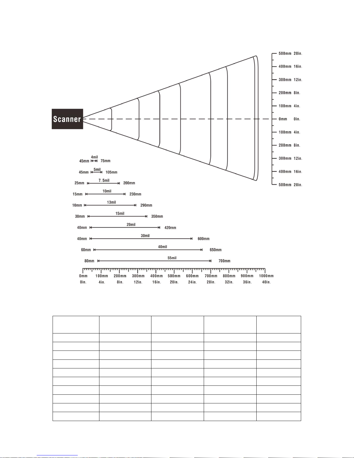
1-3 Decode zone............................................................................................................................... 4
2 Get started ......................................................................................................................................... 5
2-1 Electrical interface/Pin assignment ............................................................................................. 5
2-2 Power management.................................................................................................................... 6
3 Installation guide ................................................................................................................................ 7
3-1 Notes of installation..................................................................................................................... 7
3-2 Mounting ..................................................................................................................................... 8
3-3 Appearance of the scanner ......................................................................................................... 9
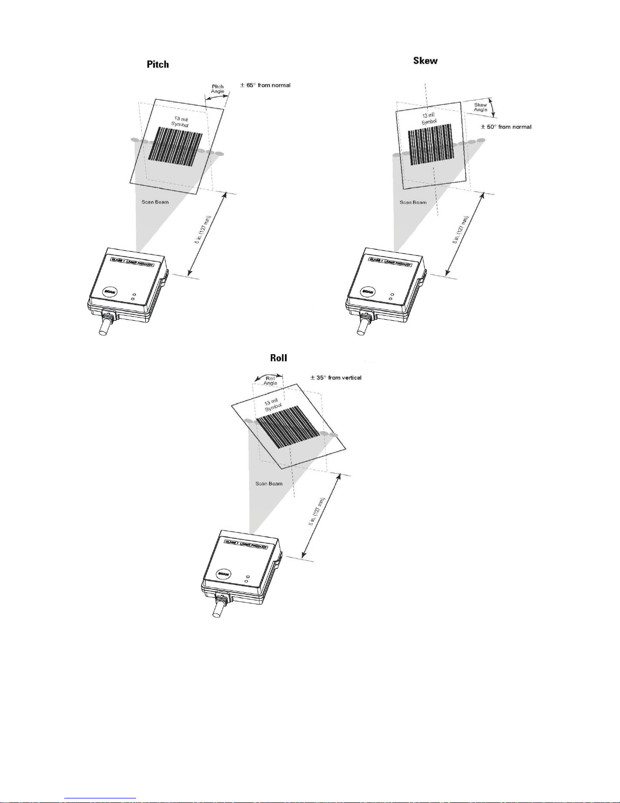
3-4 Scan angle ................................................................................................................................ 10
3-5 Tilt angle and dead zone........................................................................................................... 11
4 Parameter menus..............................................................................................................................12
4-1 Introduction ............................................................................................................................... 12
4-2 Example: configure scanner...................................................................................................... 13
4-3 RS232 interface ........................................................................................................................ 15
4-4 USB interface............................................................................................................................ 18
4-5 Scan mode & some global settings........................................................................................... 21
4-6 Indication................................................................................................................................... 27
4-7 UPC-A....................................................................................................................................... 28
4-8 UPC-E....................................................................................................................................... 30
4-9 UPC-E1..................................................................................................................................... 32
4-10 EAN-13 (ISBN/ISSN) .............................................................................................................. 34
4-11 EAN-8 ..................................................................................................................................... 36
4-12 Code 39 (Code 32, Trioptic Code 39) ..................................................................................... 38
4-13 Interleaved 2 of 5 .................................................................................................................... 41
4-14 Industrial 2 of 5........................................................................................................................ 43
4-15 Matrix 2 of 5 ............................................................................................................................ 44
4-16 Codabar .................................................................................................................................. 46
4-17 Code 128 ................................................................................................................................ 48
4-18 UCC/EAN 128......................................................................................................................... 50
4-19 ISBT 128 ................................................................................................................................. 52
4-20 Code 93 .................................................................................................................................. 54
4-21 Code 11 .................................................................................................................................. 56
4-22 MSI/Plessey ............................................................................................................................ 58

iv
4-23 UK/Plessey ............................................................................................................................. 60
4-24 China Post .............................................................................................................................. 62
4-25 GS1 DataBar (GS1 DataBar Truncated) ................................................................................. 63
4-26 GS1 DataBar Limited .............................................................................................................. 64
4-27 GS1 DataBar Expanded.......................................................................................................... 65
4-28 G1-G4 & FN1 substitution string setting.................................................................................. 66
4-29 G1-G4 string position & Code ID position ............................................................................... 70
4-30 String transmission.................................................................................................................. 71
5 Serial Communication Interface.........................................................................................................73
5-1 SCI message formats................................................................................................................ 74
5-2 BEEP ........................................................................................................................................ 75
5-3 CMD_ACK................................................................................................................................. 77
5-4 CMD_NAK................................................................................................................................. 78
5-5 DECODE_DATA ....................................................................................................................... 80
5-6 LED_CTR.................................................................................................................................. 81
5-7 REQUEST_REVISION.............................................................................................................. 82
5-8 REPLY_REVISION ................................................................................................................... 83
5-9 START_DECODE ..................................................................................................................... 84
5-10 STOP_DECODE ..................................................................................................................... 85
5-11 PARAM_DEFAULTS............................................................................................................... 86
5-12 PARAM_REQUEST ................................................................................................................ 87
5-13 PARAM_SEND........................................................................................................................ 89
5-14 CUSTOM_DEFAULTS ............................................................................................................ 92
5-15 WAKEUP ................................................................................................................................ 93
5-16 CMD_RESTART ..................................................................................................................... 94
5-17 CMD_OUTPUTBUFFER_CTR................................................................................................ 95
6 SCI transactions ................................................................................................................................96
6-1 ACK/NAK handshaking ............................................................................................................. 96
6-2 Transfer of decode data ............................................................................................................ 97
6-3 Transaction examples............................................................................................................... 98
6-4 SCI transactions notes............................................................................................................ 101
7 Glossary..........................................................................................................................................102
8 Barcode representing non-printable character .................................................................................103
9 ASCII table ......................................................................................................................................104
10 Test chart ......................................................................................................................................105
11 Return default parameters & firmware version ...............................................................................107
12 Configuration alphanumeric value barcode (as Para. value) ..........................................................108

1
1 Specifications
1-1 Technical specifications
Table 1-1 Technical specifications @25°C
Item
Description
Input voltage
5 VDC ±5%
Scanning current
RS232: 145mA (Typ.) / 235mA (Max.)
USB: 145mA (Typ.) / 220mA (Max.)
Standby current
RS232: 0.9mA(Deep Sleep) or 25mA
USB: 30mA
Laser
650nm laser diode
Scan rate
100±10 scans/second
Scanning angle
Wide (Default): 55°±5°, decode rate: 0.5 time/scan
Narrow: 40°±5°, decode rate: 1 time/scan
Pitch angle
±65°(Condition: 100% UPC at 5 in. See Figure 1-1 )
Skew angle
±50°(Condition: 100% UPC at 5 in. See Figure 1-1 )
Roll angle
±35°(Condition: 100% UPC at 5 in. See Figure 1-1)
Decode capability
UPC-A, UPC-E, UPC-E1, EAN-13, EAN-8, ISBN/ISSN, Code 39, Code 39 full
ASCII, Code 32, Trioptic Code 39, Interleaved 2 of 5, Industrial 2 of 5 (Discrete
2 of 5), Matrix 2 of 5, Codabar (NW7), Code 128, Code 93, Code 11 (USD-8),
MSI/Plessey, UK/Plessey, UCC/EAN 128, ISBT128,China Post, GS1 DataBar
(formerly RSS) variants
Indicator
Beeper, LED
Interface supported
RS232, USB Keyboard, USB virtual COM
Scan mode
Single scan, Continuous scan, Auto-detection, Scan Output Buffering,
Command
Housing makings
Zinc alloy
Dimensions
Height× Width ×Depth: 35.7mm ×41.3mm ×17.2mm (maximum)
Weight
70g
Cable
RJ-45
Temperature
Operating: -10°C to 60°C (-4°F to 140°F);
Storage: -40°C to 70°C (-40°F to 158°F)
Humidity
5% to 90% (non-condensing)
Programming method
Method I: Manual (scanning special barcode in sequence)
Method II: Send command via RS232 interface or USB virtual COM
Firmware upgrade
Online
Decoding depth
& Max. resolution
(1 mil = 0.0254 mm)
4 mil: 45- 75 mm
5 mil: 45-105 mm
10 mil: 15-230 mm
15 mil: 30-350 mm
20 mil: 40-420 mm
30 mil: 40-600 mm
55 mil: 80-700 mm
See section “1-3 Decode zone ”for more information.
Safety and Certification
Laser safety:EN60825-1,Class 1
EMC:EN55022,EN55024
Protection class:IP64

2
Figure 1-1 Pitch, Skew and Roll

3
1-2 Default settings for various types of barcode
Table 1-2 Default settings
Code type
Read
enable
Check digit
verification
Check digit
transmission
Min. code
length
Proprietary
code ID
AIM
code ID
UPC-A
√
√
√
(12)2
A
]Em
UPC-E
√
√
√
(8)2
D
]Em
UPC-E1
√
√
√
(8)2
D
]Em
EAN-13
√
√
√
(13)2
A
]Em
EAN-8
√
√
√
(8)2
C
]Em
ISBN/ISSN1
√
√
√
(13)2
A
]Em
Code 39
√
-
-
1
M
]Am
Interleaved 2 of 5
√
-
-
6
I
]Im
Industrial 2 of 5
(Discrete 2 of 5)
-
-
-
4
H
]Im
Matrix 2 of 5
√
-
-
6
X
]Im
Codabar (NW7)
√
-
-
4
N
]Fm
Code 128
√
√
-
1
K
]Cm
UCC/EAN 128
√
√
-
1
K
]Cm
ISBT 128
√
√
-
1
K
]Cm
Code 93
√
√
-
1
L
]Gm
Code 11 (USD-8)
-
√
-
4
V
-
MSI/Plessey
-
-
-
4
O
]Mm
UK/Plessey
√
√
-
1
U
]Mm
China Post
√
-
-
(11)2
T
]Im
GS1 DataBar
√
-
-
(16)2
R
]em
GS1 DataBar Truncated3
√
-
-
(16)2
R
]em
GS1 DataBar Limited
√
-
-
(16)2
R
]em
GS1 DataBar Expanded
√
-
-
1
R
]em
Note:1The settings for ISBN/ISSN and EAN-13 must be the same except the code ID.
2Fixed-length barcodes.
3The settings for GS1 DataBar Truncated and GS1 DataBar must be the same.

4
1-3 Decode zone
Figure 1-2 Decode zone @25°C, scan angle: 55°
Table 1-3 Description of barcode patterns applied in Figure 1-2
Resolution
Barcode type
Wide-narrow
element ratio
Barcode content
Contrast
4.0 mil
Code 128
2.5:1
123456789
80%
5.0 mil
Code 39
2.5:1
123
80%
7.5 mil
Code 39
2.5:1
ABCDEF
80%
10 mil
Code 39
2.5:1
123
90%
13 mil
100% UPC
-
1234546
90%
15 mil
Code 39
2.5:1
ABCD
80%
20 mil
Code 39
2.2:1
123
80%
30 mil
Code 39
2.2:1
EF
80%
40 mil
Code 39
2.2:1
AB
80%
55 mil
Code 39
2.2:1
CD
80%

5
2 Get started
2-1 Electrical interface/Pin assignment
The scanner provides a RJ-45 cable connector.
Figure 2-1 Electrical interface/Pin
Table 2-1 lists the pin assignments of the scanner.
Table 2-1 Electrical interface/Pin assignment
Pin
RS232 cable
USB cable
1
Power(+5V)
Power(+5V)
2
Reserved
Reserved
3
Ground
Ground
4
+3.3V
(for interface auto selection purpose)
Ground
(for interface auto selection purpose)
5
TxD
Reserved
6
RxD
Reserved
7
Reserved
Reserved
8
Reserved
Reserved
9
CTS
D-
10
RTS
D+
Note: Voltage level of all RS232 Pin-outs (RXD, TXD, CTS and RTS) is 0V for logic low level and 3.3V
for logic high level. A transceiver (MAX232) PCB is designed inside the RS232 cable, and it can achieve
signal transition between TTL and RS232.

6
2-2 Power management
The scanner has two power states (Awake and Sleep).
Awake
State Sleep(Deep)
State
①
②
Figure 2-2 State machine of power management
①After finishing all operation, scanner will go to Sleep state base on Auto-sleep delay(see
“4-5
Scan mode & some global settings”
), and turn off laser, swing-mirror etc.
②Interrupted event(SCAN button is pressed or falling-edge of signal RXD occurs) will make the
scanner go to Awake state.
Note: Once the scanner is awakened, at least Auto-sleep delay must elapse before it re-enters Sleep
state.
The scanner will automatically switch to the Sleep state whenever possible, so that the scanner can
consume as less current as possible. If RS232 cable is currently applied and Deep sleep(see
“4-5 Scan
mode & some global settings”
)is enabled, the scanner can enter Sleep State more deeply, and the
supply current can drop to be 0.9mA.
In other cases, the supply current in Sleep State is 25mA (RS232 cable) or 30mA (USB cable).

7
3 Installation guide
3-1 Notes of installation
This section provides information for mounting and installing the scanner, including physical
considerations.
IP64
With IP64 approval, it is not necessary to provide extra sealing protection.
Magnetism
Mounting screws and locating pins should be non-magnetic material. It is not recommended to place any
magnetic material within 1 inch (2.54 cm) of the scanner’s optics without testing.
Figure 3-1 The zone without magnetic material placement
Optics

8
3-2 Mounting
Top view
Bottom view
Side view
Back view
Figure 3-2 Mounting diagram
Notes: Mounting screws and locating pins should be non-magnetic material. It is not recommended to
place any magnetic material within 1 inch of the scanner’s optics without testing.
Button
LEDs
Label
Beeper
Cable
Cable

9
3-3 Appearance of the scanner
Figure 3-3 Appearance of the scanner
Cable
Scan Button
Laser exit window
LEDs
Cable
Beeper
Label

10
3-4 Scan angle
Scan angle (Narrow): 40°±5°
Scan angle (Wide): 55°±5°
Figure 3-4 Scan angle

11
3-5 Tilt angle and dead zone
While scanning a bar code, do not hold the scanner vertically over it. This can cause the issue of
specular reflection which is the mirror-like reflection of light from a surface. In this case, the specular
refection is caused because the laser light reflects directly back into the scanner from the bar code. This
specular reflection can make decoding difficult. Tilt angle and dead zone are shown in Figure 3-5.
Figure 3-5 Tilt angle and dead zone

12
4 Parameter menus
4-1 Introduction
This section describes the programmable parameters, provides barcodes for programming, and
hexadecimal equivalents for host parameter programming through SCI.
The scanner is shipped with the factory default settings as described in this chapter. These
factory-default-settings values are stored in flash memory and are preserved even when the scanner is
powered down. Changes to the factory default values can be stored as custom defaults. These values
are also stored in flash memory and are preserved even when the scanner is powered down.
There are two methods to change the parameter values as described following.
Scan the appropriate barcodes as the example shown in the following Section of
“4-2 Instruction:
configure scanner by scanning configuration barcodes”
. The new values replace the existing
memory values.
Referring to the section of
“11 Return default parameters & firmware version”
, scan the Write to
custom default setting (%%WCDF) barcode to set the new values as custom defaults. The factory
default or custom default parameter values can be recalled by scanning the Restore factory defaults
(%%%DEF) barcode, or the Restore custom default setting (%%RSDF) barcode.
Send parameters through the scanner’s serial port using the SCI command PARAM_SEND. The
parameters are described in details in later sections of this chapter. Instructions for changing
parameter value using this method can be found in the section of
“5-13 PARAM_SEND”
.
Note: When the scanner is scanning, ensure the laser beam crosses every bar and space of the barcode.
See Figure 4-1.
√
×
Figure 4-1 Scanning angle

13
4-2 Example: configure scanner
Note: The factory default settings are indicated with asterisks (*) in this manual.
The scanner offers 3 methods to configure scanner: single-scan setting、multiple-scan setting and
command setting.
1、Single-scan setting
Scan the appropriate Single-scan setting barcode according to the user’s demand.
Example: Set Flow control to be none.
Steps: Scan the following barcode.
2、Multiple-scan setting
The steps of configuration are:
a) Scan the SETUP barcode on the parameter setting part.
b) Enter the option mode by scanning the Parameter name barcode.
c) To the right of the option barcode, the necessary alphanumeric inputs are listed. Scan these
alphanumeric entries (see
“12 Configuration alphanumeric value barcode”)
individually as Para.
Value.
d) Scan the END barcode, listed on the bottom of each parameter setting part.
Notes that only one parameter can be setup at each time.
Example: Set Flow control to be none.
Steps: Scan the following barcodes in order.
3、Command setting
Please refer to
“5-13 PARAM_SEND”
.

14
SETUP
Multiple-scan setting
Single-scan setting
Option barcode
Option
Alpha. value
Flow control
None
00
RTS/CTS
(Host idle:
Low RTS)
01
RTS/CTS
(Host idle:
High CTS)
02
ACK/NAK
03*
Baud rate
1200
02
2400
03
4800
04
9600
05*
19200
06
END
Single-scan setting
SETUP bar code
Alphanumeric entries
Option barcode
END barcode
SETUP barcode
SETUP bar code
Table of contents
Other Mindeo Barcode Reader manuals

Mindeo
Mindeo MD20 series User manual

Mindeo
Mindeo MP8608 User manual

Mindeo
Mindeo ES168 User manual

Mindeo
Mindeo MP82 Series User manual

Mindeo
Mindeo CS3290 User manual

Mindeo
Mindeo MP8200 User manual

Mindeo
Mindeo MS3390 User manual

Mindeo
Mindeo MS3590 User manual

Mindeo
Mindeo MD65 Series User manual

Mindeo
Mindeo CS-I Series User manual

Mindeo
Mindeo ES4200 User manual

Mindeo
Mindeo MD6600 User manual

Mindeo
Mindeo FM100 User manual

Mindeo
Mindeo MD6100S User manual

Mindeo
Mindeo MD20 series User manual

Mindeo
Mindeo MD61 Series User manual

Mindeo
Mindeo MP80 Series User manual

Mindeo
Mindeo MD29 Series User manual

Mindeo
Mindeo MD62 Series User manual

Mindeo
Mindeo CR40 Series User manual