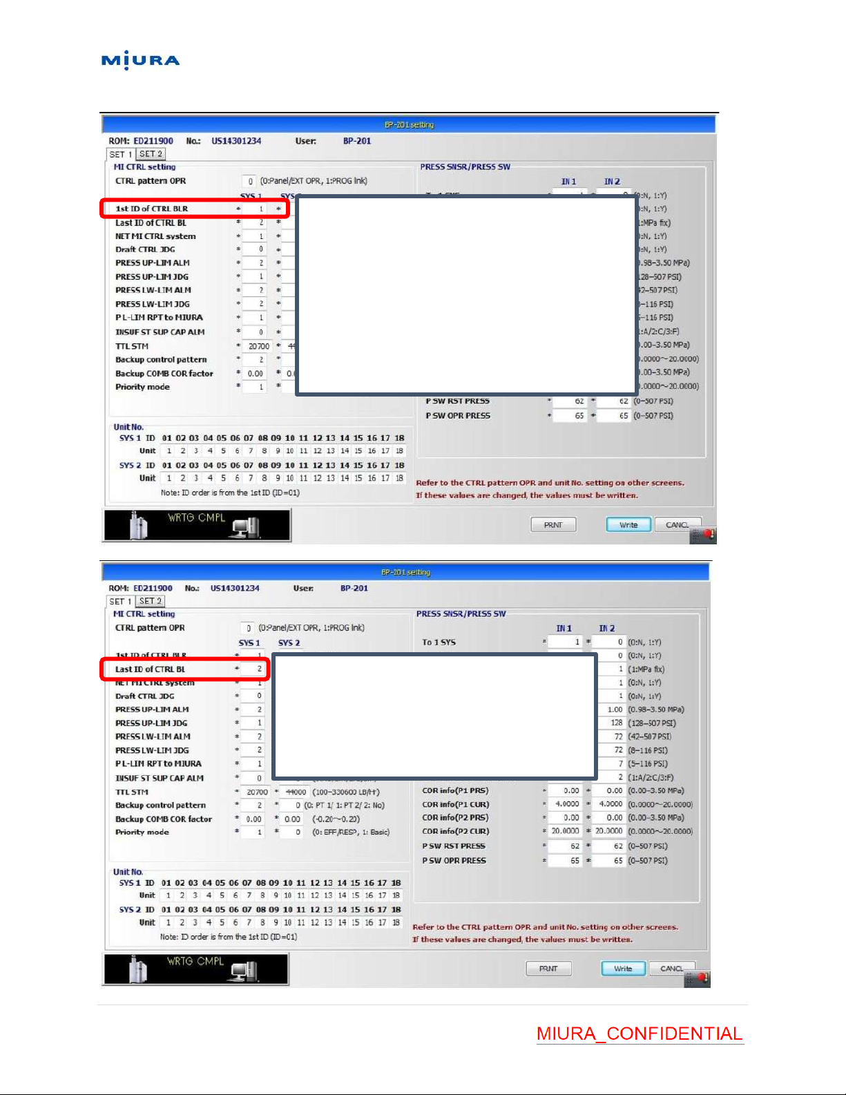
Miura BP-201 Troubleshooting guide

Version 1.3
Updated: 7/7/2021
Created By: Jacob Boyd & Technical Support
1 | P a g e
BP-201 Quick Startup Guide
Disclaimer: This guide is to be used as a supplement to the Start-up Operation Manual for the
BP-201 and should not be used as a replacement for the Start-up Manual. Please refer to the
Start-up operation manual for the BP-201 for full start-up instructions.
Step 1: Check to ensure the BP-201 is installed correctly and is wired to all applicable
equipment (ex: WP2, Boilers, Cellular MOM).
Step 2: Set all equipment ID settings on each piece of equipment. See table below.

Version 1.3
Updated: 7/7/2021
Created By: Jacob Boyd & Technical Support
2 | P a g e
Step 3: Turn power on to all BP-201 connected equipment (Do not turn on BP-201). Ensure
local boiler pressure settings are set to a higher value than the setting the BP-201 is going to be
set to.
Step 4: With power still secured to BP-201 check the switch settings according to instructions
below. Refer to the BP-201 startup manual for detailed setting information:
NET_No: Set both DIP switches to OFF
ID_NO. Settings:
•For a system with one BP set the dial to 90.
•For a system with two BP panels set one panel to 90 and the second panel to 91

Version 1.3
Updated: 7/7/2021
Created By: Jacob Boyd & Technical Support
3 | P a g e
Initialize Settings: Similar to boiler initialize settings. Turn all three DIP switches OFF
Function Settings:
1: OFF 2: ON 3: OFF 4: ON 5: OFF 6: OFF 7: OFF

Version 1.3
Updated: 7/7/2021
Created By: Jacob Boyd & Technical Support
4 | P a g e
Step 5: Turn on power to the BP-201. Check to ensure the following is displayed:
Step 6: Register the BP to the MOM-T or MOM-RT laptop (running MOM version 1.7.19 or
higher) and plug the laptop into port CN2-2 on the BP-201 CPU board. Refer to image below:

Version 1.3
Updated: 7/7/2021
Created By: Jacob Boyd & Technical Support
5 | P a g e
Step 7: Turn on the maintenance switch (SW6) on the BP-201 and enable the “save setting via
communication” setting option. See images below:

Version 1.3
Updated: 7/7/2021
Created By: Jacob Boyd & Technical Support
6 | P a g e
Step 8: Using the MOM-T/RT laptop click device setting, setting change, then select the BP-201
that is to be started. See image below.

Version 1.3
Updated: 7/7/2021
Created By: Jacob Boyd & Technical Support
7 | P a g e
Step 9: Select the Unit Setting option, select US or SI and then click the write button. When you
change the units, the pattern settings and steam capacity settings will default to the initial
values. See image below:

Version 1.3
Updated: 7/7/2021
Created By: Jacob Boyd & Technical Support
8 | P a g e
Step 10: Return to the main setting screen by hitting the cancel button. Then Click the BP-201
Setting option. Set data in “Set 1” and “Set 2” menu’s according to tables below:
If you are using a single steam header (single pressure system) then you can disregard the
System 2 (SYS 2) settings.

Version 1.3
Updated: 7/7/2021
Created By: Jacob Boyd & Technical Support
9 | P a g e
Set CTRL pattern OPR based on the preferred setting.

Version 1.3
Updated: 7/7/2021
Created By: Jacob Boyd & Technical Support
10 | P a g e
Set this to the number of
the first boiler in the
system. For a single
pressure system this would
be “1”
Set this to the total
number of boilers in the
system

Version 1.3
Updated: 7/7/2021
Created By: Jacob Boyd & Technical Support
11 | P a g e
Set this to the total steaming
capacity of the system.
Ex. two LX-300 boilers
10,350 x 2 = 20,700
Round up to nearest hundreds
Set to “2”.
“0” and “1” are currently not
used in this software revision

Version 1.3
Updated: 7/7/2021
Created By: Jacob Boyd & Technical Support
12 | P a g e
Set to “1”
Only “1” is used in the North
American Market
Set the pressure
sensor range:
Set to “2”
1: 128 psi
2: 276 psi
3: 414 psi

Version 1.3
Updated: 7/7/2021
Created By: Jacob Boyd & Technical Support
13 | P a g e

Version 1.3
Updated: 7/7/2021
Created By: Jacob Boyd & Technical Support
14 | P a g e
Set the upper limit for
the control range
setting. This limits
how high the
customer can set the
pressure range.
The standard setting is
probably sufficient.
Set the lower limit for the
control range setting. This limits
how low the customer can set
the pressure range.
The standard setting is 7 psi. If
the setting is too low and the
loads vary, a small range may
cause hunting and overshoot.

Version 1.3
Updated: 7/7/2021
Created By: Jacob Boyd & Technical Support
15 | P a g e
1. Set the Date
2. Set the MOM phone number
or ip address (cellular MOM)
3. Click “Apply to all”
4. Click “Write” to save to settings to the BP-201

Version 1.3
Updated: 7/7/2021
Created By: Jacob Boyd & Technical Support
16 | P a g e
Step 12: Press the write button to write all the settings that were entered in step 11. Press the
cancel button to return to the main setting screen. Then select the “HRCY DISP” menu followed
by the “HRCY code(A) Simple SET” menu. See image below:

Version 1.3
Updated: 7/7/2021
Created By: Jacob Boyd & Technical Support
17 | P a g e
Boilers will be registered into the hierarchy according to the numbering scheme below:
Step 14: Click the write option. Then select the “W-EQPT” menu and set the information
according to the picture below.
Boiler 1: 0101
Boiler 2: 0201

Version 1.3
Updated: 7/7/2021
Created By: Jacob Boyd & Technical Support
18 | P a g e
Step 16: Select cancel to return to the main setting menu. Then select the “Contact IN” menu.
Input the settings for the BP-201 pressure switch contact according to the image below. Any
additional optional contact inputs will be configured on this page if they are equipped:

Version 1.3
Updated: 7/7/2021
Created By: Jacob Boyd & Technical Support
19 | P a g e
Step 18: Turn the maintenance switch off, ensure BP-201 starts up and is like the image below.
Note: If only one system is programed into BP-201 there will be only one pressure indication.
See image below.

Version 1.3
Updated: 7/7/2021
Created By: Jacob Boyd & Technical Support
20 | P a g e
Step 19: Set touch screen settings (PRO distribution, Control function, Alarm pressure & Load
following). See images below.
Other manuals for BP-201
1
Other Miura Boiler Supplies manuals

Miura
Miura WP2-200A User manual

Miura
Miura CONNECT User manual

Miura
Miura WP2-200A User manual

Miura
Miura EJ-210 User manual

Miura
Miura Comm-Link User manual

Miura
Miura CMU-324HE User manual

Miura
Miura BP-201 User manual

Miura
Miura MP1-200 User manual

Miura
Miura CMU-324HE User manual

Miura
Miura STEAM EO-010A User manual