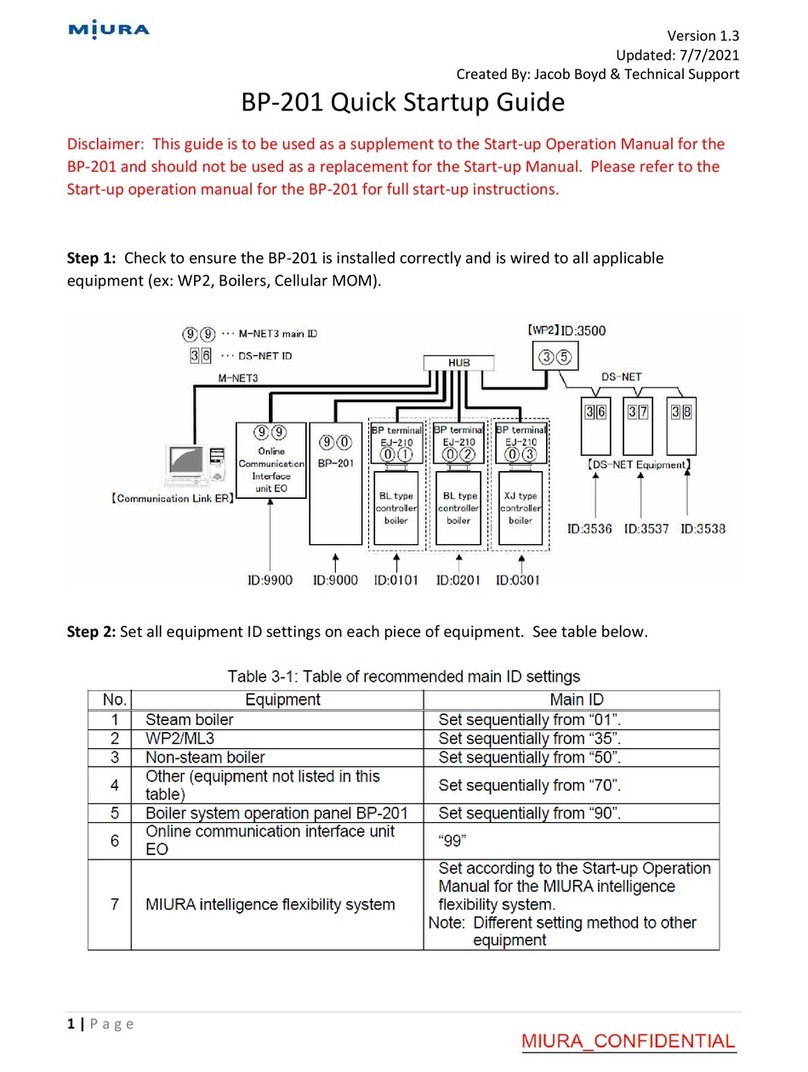
Miura WP2-200A User manual

INSTALLATION
MANUAL
WP2-200A
MIURA CO., LTD.
This document was formulated in Japan. Comply with the
regulations and standards of the country of usage.
The specifications of products and components may vary
with country of usage and the site situation.
INFORMATION IN THIS MANUAL MAY BE CHANGED
WITHOUT NOTICE.
Manual Code No. S836-583-8010

アース端子
Applicable to All Water Treatment Equipment (Safety Information)
Document No.: 98-001-04
<Precautions for installation and use> —Safety information
When installing and using a piece of water treatment equipment, you are obligated as an operator to submit official
notification, and to install, construct and utilize your equipment strictly in compliance with applicable laws and regulations.
In order that your MIURA water treatment equipment can be put to safe and reliable use, it is crucial that in addition to
fulfilling these legal obligations, you also establish and implement a safety management system.
This section highlights situations where failure to follow MIURA guidelines
could lead to serious injury or death.
(1) Relocation & Resale
If you intend to relocate or sell your MIURA water treatment equipment, contact your dealer
or MIURA sales office in order that installation work can be carried out correctly and that
the peripheral equipment may be set up. In addition, ensure that Operation Manual and the
like are kept in order that they may also be provided to the new owner in the event of
resale.
(2) Prohibition of Modification without Permission
Customization or modification not recommended by MIURA may present safety problems
and is therefore prohibited. If you wish to modify your water treatment equipment, contact
your dealer or MIURA sales office in advance. It should be noted that MIURA will accept no
responsibility for the outcome of unapproved customization.
(3) Drain Piping
Ensure that drain piping is fixed securely in place to prevent it from moving in reaction to
drain discharge and that the end of the piping opens in a safe location such as a pit.
Failure to observe this precaution may lead to electric shock or other problems due to
splashing of water. Do not touch the drain piping as the discharged water may be high
temperature in some cases depending on the product used. Touching the drain pipe may
result in burns or other injury.
High concentration water may be discharged from the water treatment equipment
temporarily in some cases. Additional water treatment may be necessary to prevent lakes
and other bodies of water from being adversely affected depending on the volume of drain
and the water quality.
(4) Electrical Work
When connecting a power supply to the water treatment equipment, use wire of the
specified rating and ensure that the equipment are correctly grounded (Japanese D-type
grounding work or better). Furthermore, a dedicated power supply should be used, and an
earth leakage circuit breaker (with overcurrent protection) should be installed. If this
precaution is not observed, serious accidents such as electric shock and the outbreak of
fire may result.
NOTE
(1) Exporting from Japan
Under the Foreign Exchange and Foreign Trade Act, permission must be granted in advance by the Government of
Japan for products under export control to be shipped overseas. In addition, many countries have enacted regulations
and the like covering the import and usage of products from Japan—in certain cases, import and use of these products is
prohibited. Therefore, if you wish to export your water treatment equipment from Japan, contact your dealer or MIURA
sales office in advance.
(2) Water Treatment Equipment Installation
Ensure that the installation work for the water treatment equipment is carried out correctly as set forth in the applicable
MIURA Installation Manual. Furthermore, anybody who will work with the water treatment equipment should carefully
study the content of the Operation Manual in advance and ensure that it is fully understood.
(3) Water Leakage Countermeasures
Factors such as loose connectors and aging of pipe materials can lead to water leakage. It
is important that drain ditches be setup for the water treatment equipment and all peripheral
equipment. (In order to prevent water from leaking outside the room or downstairs, set up a
drain ditch that completely encloses the whole equipment, ensure that the floor itself is
waterproof, make the floor slope downward to the drain port, and take any other necessary
steps.)
ブロー配管
ピット
Drain piping
Pit
Drain ditch
WARNING
Ground
terminal

Applicable to All Water Treatment Equipment (Related Laws and Regulations)
Document No.: 98-002-03
<Precautions for installation and use> —Related laws and regulations
1) The table below shows part of the laws and regulations on equipment installation and use. Refer to the separate
document for more information on other relevant laws and regulations.
(There are also prefectural and municipal ordinances; therefore, contact the supervisory authority or competent
authority for more information.)
2) The information listed in the table was created based on the laws and regulations in effect when the information was
published.
3) The documents to be submitted and their destination vary depending on your equipment and facilities.
If you have any questions, contact your nearest dealer, MIURA sales office, or the competent supervisory authority.
4) The laws and regulations listed below may not apply to all water treatment equipment. Refer only to those laws and
regulations that apply to your equipment and facilities.
Related laws
and regulations
Form(s) to be
submitted
Destination
Submission
timing
Remarks
Water Quality
Pollution Control
Act, River Act,
Sewerage Service
Act, etc.
Verification required from local towns and cities in which
the water treatment equipment or other equipment is
installed.
(The laws and regulations in some areas may be defined
even more specifically in accordance with regional
regulations.)
Drain water may be produced depending on the type
of water treatment equipment and equipment
operation. Drain water must be treated in other ways
to prevent it from damaging waterways and the like.
In cases where the total amount of drain water
exceeds the legal amount on a per-plant basis or
where the equipment is used at specified facilities,
an application is necessary. However, the conditions
may vary from region to region. Accordingly, you
should contact your local authorities for more
information.
Regional Pollution
Prevention
Ordinance
Notification as
required by the
applicable ordinance
As set forth by
the relevant
regional
authorities
As set forth by
the relevant
regional
authorities
Applicability is defined independently by regional
pollution prevention ordinances based; accordingly,
you should contact your local authorities for more
information. (Certain regional ordinances concerning
air pollution, noise, vibration, drain water, and the
like may supersede the corresponding national
regulations.)
Water Supply Act
None
—
—
(Prohibition of direct waterworks contact)
Water treatment equipment (excluding certified
equipment) cannot be connected directly to
waterworks. Instead, it is necessary to either set up
a feed water tank or to isolate the systems using, for
example, a float valve.
Details may vary from region to region; accordingly,
you should contact your local authorities for more
information.
Design specifications
for dedicated
waterworks,
Notification of the
start of feeding water
As set forth by
the relevant
regional
authorities
—
Business operators are to submit notification to local
governments for drinking water wells for industrial
use in facilities where the volume of water intake
exceeds the allowed quantity as prescribed by law
which require the use of dedicated waterworks
systems regardless of the form of usage. Contact
your local authorities for details.
Act on
Maintenance of
Sanitation in
Buildings
None
—
—
Buildings are to be preserved and maintained
(through cleaning, water quality analysis, and other
activities) in accordance with Hygiene Control
Standards.
Food Sanitation
Act
No notification made
for equipment and
related matters
—
—
Measures are to be implemented to maintain
hygiene and safety and prevent sanitation hazards
in accordance with applicable laws.
Industrial Safety
and Health Act
None
—
—
When using substances specified in applicable laws
(such as specified chemical substances), a qualified
operator must be selected, all such substances are
to be handled and managed in accordance with
applicable laws, and the operator’s healthcare is
necessary.
Poisonous and
Deleterious
Substances
Control Act
None
—
—
All such substances are to be stored and managed
in accordance with applicable laws. Chemical
substances are to be handled properly in
accordance with the guidance and information listed
on the SDS for the relevant material.
Fire Service Act
Notification as set
forth by local fire
departments
The nearest
fire department
Prior to the
start of work
Local fire chiefs or fire department chiefs must be
notified in advance of any plans for any party to use
or store certain substances (chemical substances
and other materials) of a designated quantity as
specified by applicable laws and regulations.

Document No.: S836-583-8010
Introduction
This document is an instruction manual for transport and installation of the water treatment control
board for boiler WP2-200A (hereinafter,”the control board”).
When installing the Unit, read and understand this manual well and install it safely. In this manual,
risk and damage associated with the Unit are classified in the following three levels.
Indicates an imminently dangerous situation which leads to
serious injury or death to the user, if the product is mishandled.
Indicates a situation which might cause serious injury or death to
the user, if the product is mishandled.
Indicates a situation which might cause minor injury to the user or
the occurrence of physical damage only, if the product is
mishandled.
【Explanation of Notation】
The meanings of the symbols used in this manual are as shown below.
Indicates a prohibited action (what you must not do).
Indicates a possibility of injuries when the specified position is touched.
Indicates a possibility of electric shock when the product is handled with
wet hands.
Indicates an action to be taken according to an instruction (what to be
executed).
Indicates an action connecting a grounding wire.
Indicates a caution.
Indicates a possibility of injury due to high temperatures under specific
conditions.
NOTE
Describes the precautions to prevent failures of the control board, points
to perform effective operation, and useful information to know.
DANGER
WARNING
CAUTION

Document No.: S836-583-8010
Table of Contents
1. Preparation for Installation························································································· 1
1.1 Checking the Installation Location·············································································1
1.2 Wearing Protective Equipment ·················································································1
1.3 Checking the Model ·······························································································1
1.4 Checking the Provided Items ···················································································2
2. Carrying the Control Board························································································ 2
2.1 Dimensions and Mass ····························································································2
2.2 Carrying the Control Board······················································································2
3. Installation·············································································································· 3
3.1 Installation Location and Space················································································3
3.2 Installation············································································································3
4. Electrical Wiring ······································································································ 4
4.1 Electrical Wiring Guidelines ·····················································································5
4.2 Bar Terminals and Tools··························································································5
5. List of Alarms·········································································································· 7
5.1 Alarms Evaluated in the Control Board·······································································7
5.2 Alarm Notifications from Monitored Equipment ····························································9
◆Installation Checksheet
◆Installation Diagram
・Main Unit Installation
・Feed Water Tank Installation
◆Wiring Diagram
・External Wiring Diagram
・Wiring①
・Wiring②<Power Supply and Output Terminal Blocks>
・Wiring③<I/O Board Terminal Blocks>
・Wiring④<Chemical Feeder>

Document No.: S836-583-8010
1
1. Preparation for Installation
1.1 Checking the Installation Location
Make the following checks before installing the control board.
NOTE
(Installation location)
•The product is designed for indoor installation only. Avoid locations subject to rain or
direct sunlight.
•The product is not to be used in areas where salt damage occurs.
(Electrical wiring work)
•Provide a power supply that is available 24 hours a day.
•A 120 VAC, single-phase power supply is required.
1.2 Wearing Protective Equipment
Wear protective equipment such as a helmet, protective glasses, protective mask, safety shoes,
and leather gloves as required for the task.
1.3 Checking the Model Table 1-1 Specification Table
Item
—
Water treatment control board for boiler
Model(Note 1)
—
WP2-200A2,A4
Power supply voltage
—
120 VAC, 60 Hz, single-phase
Rated power consumption(Note 3)
W
36
Operating ambient temperature
range
°F
41 to 113
Humidity range
%RH
20 to 90 (no condensation)
Installation method
—
Indoor, wall-mounted
Overall dimensions
in.
24” (W) × 30” (H) × 65/8”(D)
Product mass
lb
60
Casing paint color
—
White
Compatible networks
M-NET3, DS-NET
Note 1: The last number of the model name (2 or 4) indicates the number of built-in earth leakage
circuit breakers (with overcurrent protection) for the chemical feeder power supply.
Note 2 A communication conversion function is provided to connect DS-NET-compatible water
treatment equipment to M-NET3.
Note)The control board cannot be connected to M-NET.
Over the M-NET3 communication line, water treatment equipment information can be
transmitted to the boiler room operation panel (BP-201) and central management system
(Miura Intelligence Flexibility System), and communications with a MIURA office can be
performed.
Note 3 The rated power consumption does not include the power consumption of external
connected devices, such as chemical feeders.
Note 4 This table shows the specifications for the WP2-200A (standalone type).

Document No.: S836-583-8010
2
1.4 Checking the Provided Items
The provided items are listed in the table below.
Table 1-2: Provided items
Part name
Model
WP2-200A
Main unit
1
Operation Manual
1
Note 1:Anchor bolts and wiring materials required for installation and wiring are to be procured
on site.
2. Carrying the Control Board
2.1 Dimensions and Mass
The table below shows the external dimensions and mass of the control board.
Table 2-1 External dimensions and mass of the product
Item
-
Water treatment control board for boiler
Model
-
WP2-200A
Overall dimensions
in.
24” (W) × 30” (H) × 65/8”(D)
Product mass
lb
60
2.2 Carrying the Control Board
The main unit packaging is shown in the figure below.
Figure 2-1: Main unit packaging
NOTE
•Do not place any weights on the equipment. This may deform the casing.
•Do not place the packaging up-side-down and do not stand it vertically.
This may deform the casing.
When carrying the control board, take due care not to drop it.
Failure to observe this precaution may cause injury due to receiving its weight.
WARNING

Document No.: S836-583-8010
3
3. Installation
3.1 Installation Location and Space
1) Ensure that adequate space is available to work with the control box door open for
adjustment or maintenance. Ensure that the space of 300 mm or more is available in
addition to the space to open and close the door.
Figure 3-1: Installation space
Figure 3-2: Installation method
NOTE
•The control board is designed for indoor installation.
•Check that the wall has adequate load-bearing capacity. (Product mass: 60 lb)
•Hole-in anchors and anchor bolts are to be procured separately.
3.2 Installation
When installing the main unit, refer to the diagram “Main Unit Installation” at the end of this
manual.
Do not install on a wooden wall or a wall that may corrode.
Fix the equipment securely using the specified anchor bolts.
If the equipment falls, it may cause injury.
WARNING

Document No.: S836-583-8010
4
4. Electrical Wiring
NOTE
•As the main power supply, install an independent earth leakage circuit breaker with overcurrent
protection (120 VAC rated voltage, 15A rated current, 30 mA rated sensitivity current) within 118”
of a trunk line branch point in the low-voltage indoor wiring.
•Connect a grounding wire at least as large as the power supply wire diameter (AWG14 or larger)
to terminal E on the equipment terminal block and perform the grounding work (D-class
grounding or better).
•Use a AWG14 or larger CV cable (or equivalent) as the power supply wire. Connect the ground
phase to terminal N on the power supply terminal block.
•Connect AWG16 VCTF cable (or equivalent) as the chemical feeder power supply wire.
•Use AWG16 or larger CVV cable (or equivalent) as contact output signal wires and chemical feed
pump drive signal wires. Connect the grounding wire from the chemical feeder to the FG terminal.
•Use AWG16 or larger CVV cable (or equivalent) as water level input wires and contact input
signal wires.
•Use AWG16 or larger shielded wire (AWG16 CVV-S cable is recommended) as flowmeter wires.
•To connect wires to the screw terminal block at the bottom of the equipment, use insulated crimp
terminals suitable for the terminal block width and screw size. Do not bend the terminals before
crimping them.
Do not operate the power switch with wet hands.
Failure to observe this precaution may lead to electric shocks.
During power source installation work, use a specified wire diameter for connection
and ensure that a ground is established.
(Japanese D-class grounding (third-class grounding) or better)
Furthermore, a dedicated power supply should be used and an earth leakage circuit
breaker (with overcurrent protection) should be set up. If this precaution is not
observed, serious accidents such as electric shock and outbreak of fire may result.
Protect wires in conduits.
Failure to observe this precaution may result in an electric shock due to damaged
insulation.
Turn OFF the power to all peripheral devices connected to the control board before
wiring the control board. Failure to observe this precaution may result in an electric
shock.
WARNING

Document No.: S836-583-8010
5
•Use the following crimp terminals for connections to the terminal block for bar terminals on the
circuit board. Crimp the terminals using a suitable crimp tool.
Ferrule terminal: WAGO/216-202 (AWG20)
WAGO/216-203 (AWG18)
WAGO/216-244 (AWG16)
Bar terminal: NICHIFU/TGN TC-1.25-9T (AWG22 to 16)
•For details about the ferrule terminals, refer to “4.2 Bar Terminals and Tools”.
•Protect communication wires (twisted-pair cable), power supply wires, and control wires in
conduits. Use separate conduits and wiring routes for the communication wires, power supply
wires, and control wires, respectively.
4.1 Electrical Wiring Guidelines
For general details about the electrical wiring, refer to the “Wiring” diagrams at the end of this
manual.
4.2 Bar Terminals and Tools
Use the following bar terminals specified by MIURA according to each wire diameter for the
terminal processing of the signal wires connected to a circuit board.
Table 4-1: Bar terminals
Photograph
Part name
Color
Model No.
Applicable wire diameter
Applicable
insulation
diameter
Ferrule
(WAGO)
Gray
216-202
AWG20
φ2.8 mm
Red
216-203
AWG18
φ3.0 mm
Black
216-244
AWG16
φ3.4 mm
Ferrule
(PHOENIX
CONTACT)
Gray
AI 0.75-8 GY
AWG20
φ2.7 mm
Red
AI 1-8RD
AWG18
φ2.9 mm
Black
AI 1.5-8 BK
AWG16
φ3.3 mm
Center-pin
bar terminal
(NICHIFU)
Clear
TGN TC1.25-9T
AWG22 to 16
φ3.6 mm

Document No.: S836-583-8010
6
Use the appropriate crimp tool from the table below.
Table 4-3: Crimp tools for bar terminals
Crimp tool
Manufacturer
Model No.
Applicable
terminal
Crimped wire
range
WAGO
206-204
Ferrule
AWG24 to 12
PHOENIX
CONTACT
CRIMPFOX6
AWG24 to 10
NICHIFU
NH65
(NH11/NH32)
Center-pin
bar terminal
AWG22 to 14
The ferrules (bar terminals) and crimp tools manufactured by WAGO and PHOENIX CONTACT
are interchangeable. However, the NICHIFU crimp tool must be used for NICHIFU bar terminals.

Document No.: S836-583-8010
7
5. List of Alarms
5.1 Alarms Evaluated in the Control Board
Alarm symptom
Alarm
code
Event information
Effect on
operation
Manual reset
Integrated
output*3
User
mode
Maintenance
mode
Feed water
alarm
A200-09
Feed water tank low water level
×
×
○
1
Safety stop
A510-66
Safety-Key not connected 2
○
×
×
1,2
Feed water
error
C200-03
Water level SW input logical error
×
×
○
1
C200-16
Bypass water feeding
○
×
○
1
C200-18
Feed water tank high water level
×
×
○
1
C200-19
Tank feed water flow detected
during feed water stop
×
×
○
1
Control error
C500-01
Memory data error(ROM)
×
×
○
1
C500-02
Memory data error (EEPROM)
×
×
○
1
Communication
error
C590-16
Chemical feed control information
collection not available
○
×
○
1
C590-18
Report delay alarm 2
×
×
○
1
Utility caution
C700-08
Power not detected (Chemical
feeder 1)
×
×
○
1
C700-09
Power not detected (Chemical
feeder 2)
×
×
○
1
C700-10
Power not detected (Chemical
feeder 3)
×
×
○
1
C700-12
Power not detected (Chemical
feeder 4)
×
×
○
1
C810-01
Speficied amount of chemical fed
during chemical refill request
(Chemical feeder 1)
○
×
○
1
C810-02
Speficied amount of chemical fed
during chemical refill request
(Chemical feeder 2)
○
×
○
1
C810-03
Speficied amount of chemical fed
during chemical refill request
(Chemical feeder 3)
○
×
○
1
C810-04
Speficied amount of chemical fed
during chemical refill request
(Chemical feeder 4)
○
×
○
1
C810-05
Chemical not discharged during
chemical feed
(Chemical feeder 1)
×
○
○
1
C810-06
Chemical not discharged during
chemical feed
(Chemical feeder 2)
×
○
○
1
C810-07
Chemical not discharged during
chemical feed
(Chemical feeder 3)
×
○
○
1
C810-08
Chemical not discharged during
chemical feed
(Chemical feeder 4)
×
○
○
1

Document No.: S836-583-8010
8
Alarm
symptom
Alarm
code
Event information
Effect on
operation
Manual reset
Integrated
output*3
User
mode
Maintenance
mode
Drain check
F220-01
Condensate temperature out of
normal range (low)
×
○
○
2
F220-02
Condensate temperature
out of normal range (high)
×
○
○
2
Control check
F500-01
Memory data check (RAM)
×
×
×
No output
Sensor check
F530-20
Detected flow is low (during
water feeding)
×
○
○
2
F530-41
Tank conductivity out of output
range (low)
×
○
○
2
Communicatio
ns check
F590-16
Monitor equipment
communication not available 2
×
○
○
2
Peripheral
management
check
F810-04
Chemical refill input detected
(Chemical feeder 1)
×
○
○
2
F810-05
Chemical refill input detected
(Chemical feeder 2)
×
○
○
2
F810-06
Chemical refill input detected
(Chemical feeder 3)
×
○
○
2
F810-11
Chemical refill input detected
(Chemical feeder 4)
×
○
○
2
External
contact input
A/C/F599
~899-01
External contact input detected
×
*1
*1
*2
A/C/F599
~899-02
External contact input detected
×
*1 In the case of the external contact input # alarms, Alarms and Cautions can be manually reset on the
maintenance monitor screen only, while the Notices can be manually reset on either the maintenance
monitor screen or user monitor screen.
*2 In the case of the external contact input # alarms, Alarms and Cautions are output to “integrated alarm
output 1”, while the Notices are output to “integrated alarm output 2”.
*3 The alarms output to each integrated alarm output can be set as required. The table shows the default
settings. However, alarms not output to either integrated alarm output are not displayed on the LCD
screen.

Document No.: S836-583-8010
9
5.2 Alarm Notifications from Monitored Equipment
Alarms from equipment connected via DS-NET can be notified by the control board. The alarm
is reset when it is confirmed at the equipment where it was evaluated.
Alarm
symptom
Alarm
code
Event information
Effect
on
operatio
n
Manual reset
Integrated
output*3
User
mode
Maintenanc
e mode
Peripheral
management
check
—
CMU-H cartridge replacement
timing
×
×
×
2
—
CMU-G cartridge replacement
timing
×
×
×
2
—
CMU-CL cartridge replacement
timing
×
×
×
2
Peripheral
equipment
check
—
CMU-H unconfirmed alarm
detected
×
×
×
2
—
CMU-G unconfirmed alarm
detected
×
×
×
2
—
CMU-CL unconfirmed alarm
detected
×
×
×
2
—
MW unconfirmed alarm
detected
×
×
×
2

WP2-200A Installation Checksheet
WARNING
When installing the WP2-200A, use this checksheet to ensure correct
installation. Incorrect installation may result in a serious accident.
(For details about other installation precautions that are not listed in this
checksheet, read the Installation Manual.)
CUSTOMER
NAME
DATE
PERSON IN
CHARGE
INSTLLATION
CONTRACTOR
NAME
LOT No.
COMMENT
<Fixing the main unit>
・Securely fix the main unit
using bolts at 4 points.
Check
Installation check items
Item
Check
Ensure that the operation environment (temperature and humidity) is appropriate.
Ensure that the control board is installed indoors, away from rain.
Ensure that main power supply is 120 VAC, single-phase.
Ensure that main power supply is dedicated for the control board and equipped
with an earth leakage circuit breaker (with overcurrent protection).
Ensure that D- class grounding or better is performed for the ground terminal.
Ensure that main unit is securely fixed with 4 bolts.
<Electrical Work・Main power side>
・Use an earth leakage
circuit breaker (with
overcurrent protection).
・Provide a dedicated
power supply.
Check
Check
<Electrical Work・WP2-200 side>
・Firmly connect the specified power supply wire
(AWG14 or larger CV cable (or equivalent)).
・Ensure that a ground is established.
(D-class grounding or better)
Check
Check


Other manuals for WP2-200A
1
Table of contents
Other Miura Boiler Supplies manuals

Miura
Miura EJ-210 User manual

Miura
Miura STEAM EO-010A User manual

Miura
Miura Comm-Link User manual

Miura
Miura BP-201 User manual

Miura
Miura BP-201 Troubleshooting guide

Miura
Miura CONNECT User manual

Miura
Miura WP2-200A User manual

Miura
Miura CMU-324HE User manual

Miura
Miura MP1-200 User manual

Miura
Miura CMU-324HE User manual