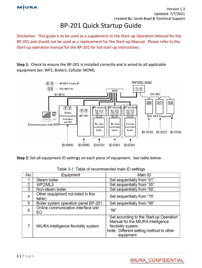
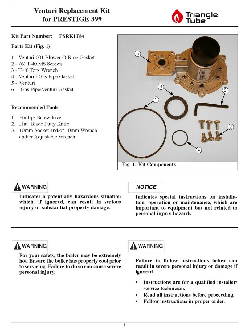
Miura CMU-324HE User manual

INSTALLATION
AND
START-UP OPERATION MANUAL
Colormetry
CMU-324HE
Water Hardness Leakage
(For outside Japan)
MIURA CO.,LTD.
This document was formulated in Japan. Comply with
the regulations and standards of the country of use
regarding installation and usage.
The specifications of products and components may
vary with country of use and the site situation.
INFORMATION IN THIS MANUAL MAY BE
CHANGED WITHOUT NOTICE.
Manual Code No. S855-080-8911

アース端子
Applicable to All Water Treatment Equipment (Safety Information)
Document No.: 98-001-06
<Precautions for installation and use> — Safety information
When installing and using a piece of water treatment equipment, you are obligated as an operator to submit official
notification, and to install, construct and utilize your equipment strictly in compliance with applicable laws and regulations.
In order that your MIURA water treatment equipment can be put to safe and reliable use, it is crucial that in addition to
fulfilling these legal obligations, you also establish and implement a safety management system.
This section highlights situations where failure to follow MIURA guidelines
could lead to serious injury or death.
(1) Relocation & Resale
If you intend to relocate or sell your MIURA water treatment equipment, contact your dealer or
MIURA sales office in order that installation work can be carried out correctly and that the
peripheral equipment may be set up. In addition, ensure that Operation Manual and the like are
kept in order that they may also be provided to the new owner in the event of resale.
(2) Prohibition of Modification without Permission
Customization or modification not recommended by MIURA may present safety problems and
is therefore prohibited. If you wish to modify your water treatment equipment, contact your
dealer or MIURA sales office in advance. It should be noted that MIURA will accept no
responsibility for the outcome of unapproved customization.
(3) Drain Piping
Ensure that drain piping is fixed securely in place to prevent it from moving in reaction to drain
discharge and that the end of the piping opens in a safe location such as a pit. Failure to
observe this precaution may lead to electric shock or other problems due to splashing of water.
Do not touch the drain piping as the discharged water may be high temperature in some cases
depending on the product used. Touching the drain pipe may result in burns or other injury.
High concentration water or non-standard pH water may be discharged from the water
treatment equipment temporarily in some cases. Additional water treatment may be necessary
to prevent lakes and other bodies of water from being adversely affected depending on the
volume of drain and the water quality.
(4) Electrical Work
When connecting a power supply to the water treatment equipment, use wire of the specified
rating and ensure that the equipment are correctly grounded (Japanese D-type grounding work
or better). Furthermore, a dedicated power supply should be used, and an earth
leakage circuit breaker (with overcurrent protection) should be installed. If this precaution is not
observed, serious accidents such as electric shock and the outbreak of fire may result.
(5) Installation of Main Unit
Do not put any combustible material inside the control box.
If anchor installation is instructed for the equipment, do not install the equipment on a wood
or combustible floor. Install the anchor bolts securely.
NOTE
(1) Exporting from Japan
Under the Foreign Exchange and Foreign Trade Act, permission must be granted in advance by the Government of Japan
for products under export control to be shipped overseas. In addition, many countries have enacted regulations and the
like covering the import and usage of products from Japan—in certain cases, import and use of these products is
prohibited. This product conforms to laws and regulations in Japan. It may not be used in the export destination country
due to the laws and regulations there. Therefore, if you wish to export your water treatment equipment from Japan,
contact your dealer or MIURA sales office in advance.
(2) Water Treatment Equipment Installation
Ensure that the installation work for the water treatment equipment is carried out correctly as set forth in the applicable
MIURA Installation Manual. Furthermore, anybody who will work with the water treatment equipment should carefully
study the content of the Operation Manual in advance and ensure that it is fully understood.
(3) Dew Condensation and Water Leakage Countermeasures
Dew drops may occur depending on environment conditions including the raw water temperature
and the atmosphere in the installation location. If necessary, take measures to prevent dew
condensation, such as installing heat insulation.
Moreover, factors such as loose connectors and aging of pipe materials can lead to water leakage.
It is important that drain ditches be setup for the water treatment equipment and all peripheral equipment. (In order to
prevent water from leaking outside the room or downstairs, set up a drain ditch that completely encloses the whole
equipment, ensure that the floor itself is waterproof, make the floor slope downward to the drain ditch, and take any other
necessary steps.)
ブロー配管
ピット
WARNING
Drain piping
Pit
Drain ditch
Ground
terminal
Combustible or
corrosive floor

Applicable to All Water Treatment Equipment (Related Laws and Regulations)
Document No.: 98-002-04-01
<Precautions for equipment installation and use> — Related laws and regulations
1) The table below shows part of the laws and regulations on the installation and use of water treatment equipment.
Refer to the separate document for more information on other relevant laws and regulations.
(There are also prefectural and municipal ordinances; therefore, contact the supervisory authority or competent
authority for more information.)
2) The information listed in the table was created based on the laws and regulations in effect when the information was
published.
3) The documents to be submitted and their destination vary depending on your equipment and facilities.
If you have any questions, contact your nearest dealer, MIURA sales office, or the competent supervisory authority.
4) The laws and regulations listed below may not apply to all water treatment equipment. Refer only to those laws and
regulations that apply to your equipment and facilities.
Related laws
and regulations
Form(s) to be
submitted
Destination
Submission
timing
Remarks
Water Quality
Pollution Control
Act, River Act,
Sewerage Service
Act, etc.
Verification required from local towns and cities in which
the water treatment equipment or other equipment is
installed.
(The laws and regulations in some areas may be defined
even more specifically in accordance with regional
regulations.)
Drain water may be produced depending on the type
of water treatment equipment and equipment
operation. Drain water must be treated in other ways
to prevent it from damaging waterways and the like.
In cases where the total amount of drain water
exceeds the legal amount on a per-plant basis or
where the equipment is used at specified facilities,
an application is necessary. However, the conditions
may vary from region to region. Accordingly, you
should contact your local authorities for more
information.
Regional Pollution
Prevention
Ordinance
Notification as
required by the
applicable ordinance
As set forth by
the relevant
regional
authorities
As set forth by
the relevant
regional
authorities
Applicability is defined independently by regional
pollution prevention ordinances based; accordingly,
you should contact your local authorities for more
information. (Certain regional ordinances concerning
air pollution, noise, vibration, drain water, and the
like may supersede the corresponding national
regulations.)
Water Supply Act
None
—
—
(Prohibition of direct waterworks contact)
Water treatment equipment (excluding certified
equipment) cannot be connected directly to
waterworks. Instead, it is necessary to either set up
a feed water tank or to isolate the systems using, for
example, a float valve.
Details may vary from region to region; accordingly,
you should contact your local authorities for more
information.
Design specifications
for dedicated
waterworks,
Notification of the
start of feeding water
As set forth by
the relevant
regional
authorities
—
Business operators are to submit notification to local
governments for drinking water wells for industrial
use in facilities where the volume of water intake
exceeds the allowed quantity as prescribed by law
which require the use of dedicated waterworks
systems regardless of the form of usage. Contact
your local authorities for details.
Act on
Maintenance of
Sanitation in
Buildings
None
—
—
Buildings are to be preserved and maintained
(through cleaning, water quality analysis, and other
activities) in accordance with Hygiene Control
Standards.
Food Sanitation
Act
No notification made
for equipment and
related matters
—
—
Measures are to be implemented to maintain
hygiene and safety and prevent sanitation hazards in
accordance with applicable laws.
Industrial Safety
and Health Act
None
—
—
When using substances specified in applicable laws
(such as specified chemical substances), a qualified
operator must be selected, all such substances are
to be handled and managed in accordance with
applicable laws, and the operator’s healthcare is
necessary.
Poisonous and
Deleterious
Substances
Control Act
None
—
—
All such substances are to be stored and managed
in accordance with applicable laws. Chemical
substances are to be handled properly in
accordance with the guidance and information listed
on the SDS for the relevant material.
Fire Service Act
Notification as set
forth by local fire
departments
The nearest fire
department
Prior to the
start of work
Local fire chiefs or fire department chiefs must be
notified in advance of any plans for any party to use
or store certain substances (chemical substances
and other materials) of a designated quantity as
specified by applicable laws and regulations.
Applicable to All Water Treatment Equipment (Related Laws and Regulations)
Document No.: 98-002-04-02
<Precautions for chemical management and handling> — Related laws and regulations
1) The table below shows part of the laws and regulations on chemical management and handling. There are also
prefectural and municipal ordinances; therefore, contact the competent administrative authority for more information.
2) This table shows the laws and regulations as of the end of September 2017. For the most up-to-date information,
contact the competent administrative authority.
3) The management and handling differ depending on the chemicals you handle. If you have any questions, contact your
nearest dealer, MIURA sales office, or the competent administrative authority.
Related laws and regulations
Destination
Submission
timing
Remarks
Common
precautions for
management and
handling
Poisonous and Deleterious
Substances Control Act
—
—
If the chemical product is a
deleterious substance, it is
necessary to perform appropriate
storage management, etc. as a
person handling it in businesses.
The laws and
regulations
applicable to each
chemical product
are described in
the SDS (Safety
Data Sheet).
Manage the
chemical products
in accordance
with the laws and
regulations. Refer
to the SDS for
details about
proper handling of
each chemical
product.
Act on Confirmation, etc. of
Release Amounts of Specific
Chemical Substances in the
Environment and Promotion
of Improvements to the
Management Thereof (Law
concerning Pollutant
Release and Transfer
Register (PRTR))
Authority in the
prefecture to
which the
location of
each office
belongs
Yearly
(April to
June)
When handling one ton or more of a
Class I designated chemical
substance (0.5 ton or more of a
specific Class I designated
substance), as mentioned in the act,
it is necessary to submit a
notification depending on the target
industry type and the number of
permanent employees.
Industrial Safety and Health
Act
—
—
According to the act, if a chemical
product containing chemical
substances that require risk
assessment in an amount equal to
or more than the cut-off value is
newly adopted, or the work
procedures to handle it are changed,
the business operator is required to
perform risk assessment.
*The risk assessment refers to the
identification of the dangers and
hazards of a chemical substance
or its manufacture, estimation of
the extent of possible harm or
health hazard to the worker, and
examination of the risk reduction
measures.

Introduction
This document describes the methods of installing the Colormetry CMU-324HE (for hardness)
(hereinafter called “the device”) to ensure its proper use.
Before installing the device, ensure that this document is read and fully understood; furthermore, the
instructions given herein should be strictly observed during installation and start-up operation.
Safety-related warnings are classified according to the following three levels, and notification of these
warnings is provided within this manual.
Indicates an imminently dangerous situation which leads to serious injury
or death to the user, if the product is mishandled.
Indicates a situation which might cause serious injury or death to the user,
if the product is mishandled.
Indicates a situation which might cause minor injury to the user or the
occurrence of physical damage only, if the product is mishandled.
[Explanation of Notation]
The meanings of the symbols used in this manual are as shown below.
Indicates a prohibited action (what you must not do).
Indicates a possibility of injury when a specific location of the product is
touched.
Indicates a possibility of electric shock when the product is handled with wet
hands.
Indicates an action to be taken according to an instruction (what to be
executed).
Indicates an action connecting a grounding wire.
Indicates a warning or caution
Indicates a possibility of injury due to high temperatures under specific
conditions.
NOTE
Used to highlight important information to prevent device malfunction as well
as tips for efficient work and other useful information.
DANGER
WARNING
CAUTION

Document No.: S855-080-8911
Table of Contents
1. Installation··················································································································· 1
1.1 Pre-installation Checklist·························································································· 1
1.2 How to Install the Main Unit ······················································································ 2
1.3 Piping··················································································································· 4
1.3.1 Drain Piping (Refer to Figure 3) ·········································································· 4
1.3.2 Feed Water Piping (Refer to Figure 4)·································································· 5
1.4 How to Connect Wiring ···························································································· 8
1.4.1 Routing the Wires (Refer to Figure 6)··································································· 8
1.4.2 Remote Signal Input ························································································11
1.4.3 Remote Alarm Output ······················································································11
1.4.4 Connecting the Reagent Cartridge Replacement Output Wiring ·······························13
1.4.5 Water Passing Output······················································································14
1.4.6 DS-NET Communication ··················································································15
1.4.7 Concentration Alarm Output ··············································································16
1.4.8 Concentration Analog Output ············································································16
1.5 Installing the Reagent Cartridge (Refer to Figure 20) ····················································17
1.6 Final Checking of Installation and Wiring before Start-up Operation·································19
2. Setting and Start-up Operation ·······················································································21
2.1 Setting the Device before Starting It ··········································································21
2.2 Checking the Device Operation and Settings Immediately after Turning on the Power·········23
2.2.1 Turning the Power on ······················································································23
2.2.2 Status Verification Test Mode ············································································25
2.3 About Items to Be Set in Setting Mode·······································································26
2.4 Verifying Monitoring Operation ·················································································30
2.5 Verifying Alarm Function ·························································································31

Document No.: S855-080-8911
1
1. Installation
We recommend to read this section before installation of the Colormetry for safety operation.
1.1 Pre-installation Checklist
(1) The raw water pressure range (both static and dynamic) must always be 0.05 to 0.49 MPa (7.2
to 71 psi). If the pressure is outside this range, a pressurizing unit or pressure reducing valve is
required.
(2) Use the device with raw water in the 5 to 40C (41 to 104F) range. Using water outside this
range may damage the internal components.
(3) Use the device in an ambient temperature range of 5 to 50C (41 to 122F). Temperatures
outside this range may cause device failure or deterioration of the reagent.
(4) The device is designed to be mounted on a wall. Install it indoors, away from rain.
(5) Avoid a location subject to direct sunlight.
(6) Install the device in such a way that the length of feed water line between the water softener
and the device is within 5 m (16.4 ft).
(7) The power supply is specified at 24 VDC, 15 W. A source is required near the device. Perform
electric work in a way that the AC adapter can be unplugged immediately if the device becomes
abnormal.
(8) The polyethylene drain pipe included in the device is 3 m (9.8 ft) long, requiring a nearby drain
ditch.
(9) Provide sufficient work space around the installed device for maintenance and operation.

Document No.: S855-080-8911
2
1.2 How to Install the Main Unit
NOTE
The reagent cartridge’s receptacle is plugged when the device is delivered. Never remove the plug
until installation is complete. (Refer to Figure 1.)
*If the plug is removed, the stirrer inside may roll and get lost. An extra stirrer is attached to the
back of the maintenance cover in case one is lost.
Figure 1: Precautions before installation
Installing the main unit (Refer to Figure 2.)
(1) Screw the provided mounting bracket to where the device is to be installed. The device should
be installed at a height to allow easy reading of the LCD display.
NOTE
Mount the bracket with its rounded side up.
(2) Hook the device on the bracket mounted on the wall and screw down the bottom end of the
device.
Plug
Reagent cartridge receptacle
Top view of device

Document No.: S855-080-8911
3
Mounting
bracket
Mounting
screw
Fixing screw hole
φ5.5 mm dia.
~
~
Rounded
corner
Mounting screw
Mounting
bracket
Fixing screw
hole
φ5.5 mm dia.
Bottom
plate
Wall surface
Figure 2: Main unit installation space
Figure 3: Drain piping installation
Back view of device Side view of device
Mounting
screw interval
225 mm
(8 3/4 in.)
Drill holes
φ4.3 mm dia.
Depth 35 mm
(1 1/2 in.)
Maintenance space
600mm (23 1/2 in.) or more
Bottom view of device Side view of device
Cylindrical part
Cylindrical
part
Drain hole
Make sure the receptacle area is
free of deformation and burrs.
Drain ditch
Filter casing assembly installation
Fixing screws for maintenance cover
Drain tube, φ8 mm dia.

Document No.: S855-080-8911
4
1.3 Piping
1.3.1 Drain Piping (Refer to Figure 3)
(1) Cut the provided drain tube, φ8 mm dia., to the length required for drainage.
(2) Insert one end of the drain tube into the cylindrical part at the bottom of the device. Run the
other end into the drain ditch.
NOTE
The insertion of the drain tube into the cylindrical part at the bottom requires some force.
Check the connection for excessive deformation or burrs before inserting the tube.
•Do not connect the drain piping to other piping.
•Be sure to drain water to the open air.
•Exercise care in keeping the drain piping free of kinks. Obstructed drain piping
may cause water leakage and misjudgment.
•In case the drain piping is clogged and the internal pressure builds up, the device
relieves the pressure through either of the methods (1) and (2) shown below.
These methods cause drain water to leak down through the bottom of the device.
Be sure not to leave anything underneath the device.
(1) Water leaks out of the tube connection at the bottom.
(2) Water leaks out of the internal piping.
Water drains out of the drain hole in the bottom of the device.
CAUTION

Document No.: S855-080-8911
5
1.3.2 Feed Water Piping (Refer to Figure 4)
(1) Connect the feed water piping to the outlet side of the water softener. (The feed water piping
connection may be made to the water softener’s water sampling valve.)
(2) Precut the included the feed water tube, φ6 mm dia., to the length required for the
installation, and firmly inserts the end into the tube joint.
(3) Assemble the filter according to the following procedure. (Refer to Figure 5.)
[1] Take the filter casing assembly out of the bag.
Don’t fit the constant flow valve yet.
[2] The filter casing comes apart into two sections. To take them apart, rotate the top and
bottom sections in the direction of arrow.
[3] Remove the filter cartridge from the box (bag). Align the outlet end of the cartridge in the
center of the top casing. Insert the cartridge all the way, then firmly tighten the bottom
casing.
(4) Insert the feed water tube firmly into the joint on the bottom casing.
(5) Assemble the filter according to the following procedure. (Refer to Figure 5.)
[1] Slowly open the sample water collecting ball valve to bleed air from inside the filter
casing assembly.
[2] Close the sample water collecting ball valve about 10 seconds after opening the valve.
(6) Fit a constant flow valve that is attached to the bag in the end of casing. (Refer to Figure 6.)
NOTE
Be careful not lose the valve during installation.
A spare constant flow valve is attached to the filter cartridge box.
The spare may be used to replace a lost valve.
(7) Screw the filter casing into the bottom plate on the device with hand. Do not use a tool. There
is no need for concern about tightening it hard, since the O-ring at the end of filter casing
provides a good seal.
(8) Use the provided cable ties to bundle the φ6 mm dia. feed water tube to the φ8 mm dia.
drain tube. (Doing so prevents the φ8 mm drain tube form dropping out of the device if
external force is exerted upon it.)
Bundle them together about 150 to 200 mm (6 to 8 in. ) away from the bottom of the filter
casing. If it is tied too close to the filter casing, undue prying force may be exerted on the joint
and cause leakage.
When bleeding air from the filter casing assembly, water is vigorously discharged
from the end of the filter casing assembly. Perform work so that the water is not
splashed.
CAUTION

Document No.: S855-080-8911
6
Figure 4: Feed water piping installation
NOTE
Where zinc or copper pipes are used, zinc or copper ions would dissolve and stagnate in the
water. The reagent in the device reacts with zinc and copper ions. Take the sample water as
close to the water softener as possible to avoid the effects of ions dissolving out of the tubes.
Filter casing assembly Fiber filter
Tube joint
Filter casing (bottom)
Filter casing (top)
φ6 mm dia.
Feed water tube
Figure 5: Filter casing assembly
Exercise care in keeping the feed water piping free of kinks.
Water softener
Ball valve
Tube joint
(provided)
φ6 mm dia.
Feed water tube
φ8 mm dia.Drain tube
Cable tie
Existing water-
sampling valve
Filter casing assembly
Tube joint
CAUTION

Document No.: S855-080-8911
7
Screw the filter casing assembly into the
bottom and insert firmly the φ6 mm feed
water tube into the tube joint.
* If the filter casing assembly is
screwed with the tube, the tube or the
tube joint may turn around and
damage itself, then the connection
becomes loose.
Before screwing in the filter,
be sure that the constant
flow valve is fitted.
Bundle the tubes together with a
cable tie.
Be sure that no undue force is
exerted on the tubes.
* If a tube is fastened tightly
until it changes its shape, a crack
may occur, leading to leakage.
Attach the warning label “Don’t apply
grease or lubricant” to the filter casing
assembly, after that, place it to be seen
from the front.
Insert the φ8 mm drain tube
properly into the cylindrical part.
Figure 6: Filter casing installation
*When you replace the fiber filter, loosen a filter casing assembly after closing the main feed water
valve of the Colormetry.
•When assembling the filter casing assembly and installing the filter casing
assembly on the Colormetry main unit, do not apply grease, lubricant, etc. This
could have a negative effect on the material of the main unit.
•If the filter casing assembly is forcibly tightened with tools, etc. when installing it on
the Colormetry main unit, the bottom plate of the main unit may crack.
As the side surface is sealed with the O-ring at the tip of the filter casing assembly,
manually tighten the filter casing assembly during installation. Exercise care in
keeping the feed water piping free of kinks and flattening.
CAUTION

Document No.: S855-080-8911
8
1.4 How to Connect Wiring
1.4.1 Routing the Wires (Refer to Figure 7)
(1) Loosen the screws at the bottom of the device, and then remove the maintenance cover.
(2) Pass the wires through the wire holder and wire hole in the bottom plate. Gather and connect
the wires to the terminal block on the circuit board.
(3) Provide a drooping slack in the wires, and clamp them down.
•Use a dedicated power supply with the specified capacity. Insufficient capacity
may cause a fire.
*When using the device in North America, be sure to use the provided AC
adapter.
Manufacturer: GlobTek, Inc.
Model: GTM96300-3024-R3A
•Install an earth leakage circuit breaker (with overcurrent protection).
Failure to observe this precaution may cause an electric shock.
•Clamp the wires down, or undue force exerted on them may damage the device.
•Provide a drooping slack for the wires to prevent leaked water from running down
the wires and causing a short circuit.
Do not operate the power switch with wet hands.
Failure to observe this precaution may result in an electric shock, etc.
Perform grounding work on the ground terminal.
WARNING
WARNING

Document No.: S855-080-8911
9
電源入力DCジャック
メンテナンスカバー固定ねじ
通信配線穴
配線ホルダ 固定を行ってください。
一回たるませてください。
入出力信号端子台
配線ホルダ
Figure 7: Wiring connection
NOTE
The device starts operating as soon as the power is turned on (system is plugged in). Activate it
only when it is ready for the start-up operation.
Output/Input signal
terminal block
Power input DC jack
Wire holder
Maintenance cover
fixing screw
Wire holder
Clamp the wires.
Provide a drooping
slack for the wires.
Communication
line wiring hole

Document No.: S855-080-8911
10
CN9
D2 D1
+ -
+ - + -
+ - + -
Remote alarm output
Remote signal input
Reagent cartridge
replacement output Concentration
analog output
Concentration alarm
output
Water passing output
DS-NET communication
*Used when connecting
to MIURA’s dedicated
network.
FG
Power input DC jack
24 VDC
Figure 8: Layout of terminal blocks on the main unit circuit board
Figure 9: Notation of functional grounding on the main unit circuit board
The caution symbol on
the DC jack CN9
indicates that the FG
terminal is functionally
grounded.

Document No.: S855-080-8911
11
1.4.2 Remote Signal Input
The remote signal input is an input for preventing monitoring while the feed water is stopped
(erroneous monitoring).
Connecting a non-voltage contact enables the device to remotely control the starting and stopping
of monitoring.
In addition, a remote signal may be utilized in either the on state or off state to start or stop
monitoring. (Either the normally-open contact (a-contact) or normally-closed contact (b-contact)
may be used.)
See Figure 10 to connect the remote signal input wiring as required.
Remote signal Connect the remote signal
wiring to a non-voltage contact.
TB2-2
M+ M- 3456
Figure 10: Remote signal input wiring connection
NOTE
•If a contact representing the feeding of water is available, connect this on a highest propriety. If
not, set up the start and stop time on the LCD display to avoid monitoring during water
stoppage and softener regeneration, or a device error may occur.
•If a remote signal is input via communications, do not connect this wiring.
1.4.3 Remote Alarm Output
•The remote alarm output is an open collector output. The maximum rating is 24 VDC, 70 mA.
•By connecting a 24 VDC power supply and 24 VDC relay, the signal can be output as contact
output when a concentration alarm or device alarm occurs in the device.
See Figure 11 to connect the remote alarm output wiring as required.
Remote alarm output
+ -
Connect the coil of
the relay with a
diode.
+ - Prepare a separate 24 VDC
power supply.
-
+
Note:Take note of
the polarity.
M+ M- 3456
Figure 11: Remote alarm output wiring connection
NOTE
When using this function, procure the following parts on-site.
Relay: 24 VDC (with coil surge suppression diode)
Power supply: 24 VDC, 10 W or above
Take proper care of the polarity when connecting the relay and power supply.

Document No.: S855-080-8911
12
•For boilers equipped with a boiler controller, by connecting the remote alarm output signal of
Colormetry to the water softener alarm terminal of the controller, a “water softener error” notice
can be output on the boiler display in case of a concentration alarm or device alarm.
NOTE
•See Figure 12 when the device is connected to a boiler equipped with a BG1/BJ1/BL11/BM11-
type controller.
•See Figure 13 when the device is connected to a boiler equipped with an XJ1-type controller.
•See Figure 14 when the device is connected to a boiler equipped with a BK-type controller.
•Note that in case of power failure of the Colormetry, the same “water softener error” notice
appears on the boiler display as the case of a concentration alarm or device alarm.
M+
M-
3
4
94
90
Colormetry terminal block
Water softener error
Remove the jumper.
Boiler terminal block
M+
M-
3
4
83
80
Colormetry terminal block
Water softener error
Remove the jumper.
Boiler terminal block
Figure 12: Connecting wiring to BG1/BJ1/BL11/BM11 Figure 13: Connecting wiring to XJ1
M+
M-
3
4
93
90
Colormetry terminal block
Water softener error
Remove the jumper.
Boiler terminal block
Figure 14: Connecting wiring to BK

Document No.: S855-080-8911
13
1.4.4 Connecting the Reagent Cartridge Replacement Output Wiring
•Reagent cartridge replacement output is an open collector output. Maximum rating is 24 VDC, 70
mA.
•By connecting a 24 VDC power supply and 24 VDC relay to the reagent cartridge replacement
output, the signal can be output as contact output when a reagent cartridge replacement notice
occurs in the device.
See Figure 15 to connect the reagent cartridge replacement output wiring as required.
試薬カートリッジ交換時期出力
+ -
7 8
+ - DC24V電源を別途
準備してください。
-
+
ダイオード付リレー
のコイルを接続して
ください。
(注)極性に注意
9 1110 12
Figure 15: Reagent cartridge replacement output wiring connection
NOTE
When using this function, procure the following parts on-site.
Relay: 24 VDC (with coil surge suppression diode)
Power supply: 24 VDC, 10 W or above
Take proper care of the polarity when connecting the relay and power supply.
Connect the coil of the
relay with a diode.
Note: Take note of
the polarity.
Prepare a separate 24
VDC power supply.
Reagent cartridge replacement output
+ -

Document No.: S855-080-8911
14
1.4.5 Water Passing Output
•Water passing output is an open collector output. The maximum rating is 24 VDC, 70 mA.
•By connecting a 24 VDC switching power supply and 24 VDC relay to the water passing output,
the signal can be output as contact output during the washing process of the Colormetry.
See Figure 16 to connect the water passing output wiring as required.
4
6
5
DC relay with built-in diode
Prepare a separate 24
VDC power supply.
Note: Take note of the
polarity.
+
-
+
-
+
-
Figure 16: Water passing output wiring connection
NOTE
When using this function, procure the following parts on-site.
Relay: 24 VDC (with coil surge suppression diode)
Power supply: 24 VDC, 10 W or above
Take proper care of the polarity when connecting the relay and power supply.
Other manuals for CMU-324HE
1
Table of contents
Other Miura Boiler Supplies manuals

Miura
Miura WP2-200A User manual

Miura
Miura STEAM EO-010A User manual

Miura
Miura BP-201 Troubleshooting guide

Miura
Miura EJ-210 User manual

Miura
Miura CONNECT User manual

Miura
Miura Comm-Link User manual

Miura
Miura CMU-324HE User manual

Miura
Miura WP2-200A User manual

Miura
Miura BP-201 User manual

Miura
Miura MP1-200 User manual