manuals.online logo
Brands
  1. Home
  2. •
  3. Brands
  4. •
  5. Monacor
  6. •
  7. Power Supply
  8. •
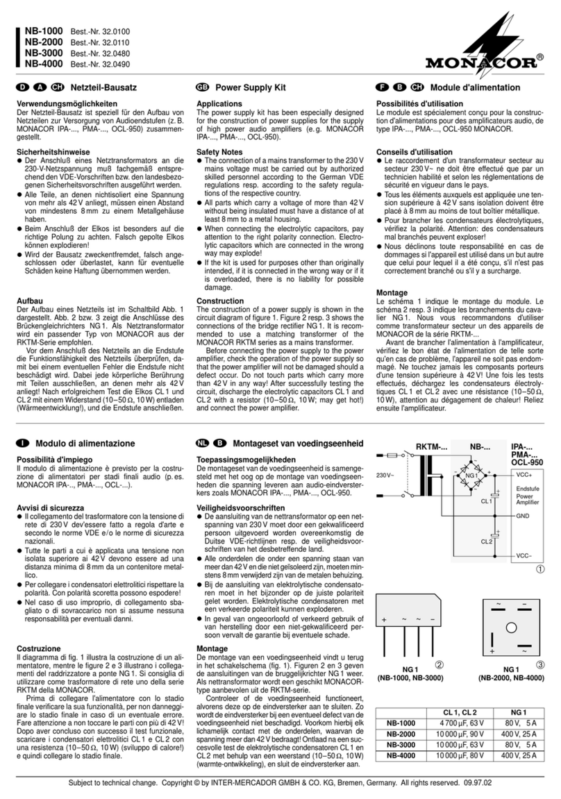
  9. Monacor AXOC-404PS User manual

Monacor AXOC-404PS User manual

ELECTRONICS FOR SPECIALISTS ELECTRONICS FOR SPECIALISTS ELECTRONICS FOR SPECIALISTS ELECTRONICS FOR SPECIALISTS ELECTRONICS FOR SPECIALISTS ELECTRONICS
AXOC-404 PS
Bestellnummer • Order Number 18.0141
MONACOR INTERNATIONAL GmbH & Co. KG • Zum Falsch 36 • 28307 Bremen • Germany
Copyright©by MONACOR INTERNATIONAL. All rights reserved. A-1998.99.01.06.2019
1
2
3
C1
V1A V1B
C 2
V2A V2B
C 3
V3A V3B
C 4
V4A V4B
4
5
6
7
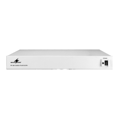
4-Channel Power Supply Unit
for AHD Cameras AXOC-4312BV
These instructions are intended for installers
of video surveillance systems with the corre-
sponding technical knowledge. Please read
the instructions carefully prior to installation
and keep them for later reference.
1 Applications
The power supply unit AXOC-404PS is designed
for connecting up to four cameras AXOC-4312BV.
A single cable is used for transmitting the video
signal of the surveillance cameras and for supply-
ing the cameras with power. This feature makes
it possible to install cameras even in places where
no power supply is available. If you use a coaxial
cable of the type RG-59, a maximum cable length
of up to 200m will be possible.
2 Safety Notes
The unit corresponds to all relevant directives of
the EU and is therefore marked with .
WARNING The unit uses dangerous mains
voltage. Leave servicing to skilled
personnel only and do not insert
anything into the air vents.
Inexpert handling may result in
electric shock.
• The unit is suitable for indoor use only. Protect
it against dripping water, splash water and high
air humidity. The admissible ambient tempera-
ture range is −10 °C to +50 °C.
• Do not place any vessel filled with liquid on the
unit, e.g. a drinking glass.
• The heat produced inside the unit must be dissi-
pated by air circulation; never cover the air vents
of the housing.
• Do not operate the unit and immediately dis-
connect the mains plug from the socket
1. if the unit or the mains cable is visibly dam-
aged,
2. if a defect might have occurred after the unit
was dropped or suffered a similar accident,
3. if malfunctions occur.
In any case, the unit must be repaired by skilled
personnel.
• Never pull the mains cable to disconnect the
mains plug from the socket, always seize the
plug.
• For cleaning only use a dry, soft cloth; never use
water or chemicals.
• No guarantee claims for the unit and no liability
for any resulting personal damage or material
damage will be accepted if the unit is used for
other purposes than originally intended, if it is
4-Kanal-Stromversorgung für
die AHD-Kameras AXOC-4312BV
Diese Anleitung richtet sich an Installateure
von Videoüberwachungsanlagen mit ent-
sprechenden Fachkenntnissen. Bitte lesen
Sie die Anleitung vor dem Betrieb gründlich
durch und heben Sie sie für ein späteres
Nachlesen auf.
1 Verwendungsmöglichkeiten
An die Stromversorgung AXOC-404PS können
bis zu vier Kameras vom Typ AXOC-4312BV an-
geschlossen werden. Das Videosignal der Über-
wachungskameras und ihre Versorgungsspan-
nung wird dabei über ein einziges Koaxialkabel
übertragen. Die Kameras können daher auch an
Orten installiert werden, an denen keine Strom-
versorgung verfügbar ist. Bei Verwendung eines
Koaxialkabels vom Typ RG-59 ist eine Leitungs-
länge bis 200m möglich.
2 Sicherheitshinweise
Das Gerät entspricht allen relevanten Richtlinien
der EU und ist deshalb mit gekennzeichnet.
WARNUNG Das Gerät wird mit lebensgefähr-
licher Netzspannung versorgt.
Nehmen Sie deshalb niemals
selbst Eingriffe am Gerät vor und
stecken Sie nichts in die Lüftungs-
öffnungen. Es besteht die Ge-
fahr eines elektrischen Schlages.
• Verwenden Sie das Gerät nur im Innenbereich.
Schützen Sie es vor Tropf- und Spritzwasser sowie
vor hoher Luftfeuchtigkeit. Der zulässige Ein-
satztemperaturbereich beträgt −10 bis +50°C.
• Stellen Sie keine mit Flüssigkeit gefüllten Ge-
fäße z.B. Trinkgläser, auf das Gerät.
• Die im Gerät entstehende Wärme muss durch
Luftzirkulation abgegeben werden. Decken Sie
darum die Lüftungsöffnungen nicht ab.
• Nehmen Sie das Gerät nicht in Betrieb und zie-
hen Sie sofort den Netzstecker aus der Steck-
dose,
1. wenn sichtbare Schäden am Gerät oder am
Netzkabel vorhanden sind,
2. wenn nach einem Sturz oder Ähnlichem der
Verdacht auf einen Defekt besteht,
3. wenn Funktionsstörungen auftreten.
Geben Sie das Gerät in jedem Fall zur Reparatur
in eine Fachwerkstatt.
• Ziehen Sie den Netzstecker nie am Kabel aus
der Steckdose, fassen Sie immer am Stecker an.
• Verwenden Sie zum Reinigen nur ein trockenes,
weiches Tuch, nie Wasser oder Chemikalien.
• Wird das Gerät zweckentfremdet, nicht richtig
angeschlossen, falsch bedient oder nicht fach-
gerecht repariert, kann keine Haftung für dar-
aus resultierende Sach- oder Personenschäden
und keine Garantie für das Gerät übernommen
werden.
Soll das Gerät endgültig aus dem Be-
trieb genommen werden, übergeben
Sie es zur umweltgerechten Entsorgung
einem örtlichen Recyclingbetrieb.
3 Anschluss
1) Die Kameras über ein 75-Ω-Koaxialkabel (z.B.
VCC-…) an die Buchsen C1–C4 (4) anschlie-
ßen.
VORSICHT An die Buchsen C1–C4 (4) nur
Kameras anschließen, die ausdrücklich für
die Verwendung mit dieser Stromversorgung
bestimmt sind. Andere Kameras könnten be-
schädigt werden.
2) Den jeweiligen Videosignalausgang V1A–V4A
(5) mit dem (AHD-)Eingang eines Videorekor-
ders oder Monitors verbinden.
3) Das beiliegende Netzkabel mit der Netz-
buchse (6) verbinden und an eine Steckdose
(230V/50Hz) anschließen.
4 Bedienung
Die Stromversorgung mit dem Schalter POWER
(1) einschalten und nach dem Betrieb wieder aus-
schalten. Die LEDs „Normal“ (2) zeigen an, dass
die Versorgungsspannung für die Kameras zur
Verfügung steht.
Leuchtet eine LED in der Reihe „Overload“ (3),
wird der maximal zulässige Versorgungsstrom
überschritten. In diesem Fall überprüfen, ob bei
der entsprechenden Kamera ein Defekt vorliegt
oder ein Kurzschluss bei der Verkabelung.
Im Fall einer geschmolzenen Netzsicherung (7)
diese nur durch eine gleichen Typs ersetzen!
5 Technische Daten
Ausgangsspannung: . . . . . ⎓ 36V
Ausgangsleistung:. . . . . . . max. 10W/Kamera
Anschlüsse:. . . . . . . . . . . . BNC
Stromversorgung: . . . . . . . 230V/50 Hz
Leistungsaufnahme: . . . . . max. 40VA
Einsatztemperatur: . . . . . . −10 bis +50°C
Abmessungen (B × H × T): 218 × 45 × 235mm
Gewicht:. . . . . . . . . . . . . . 1,6 kg
Änderungen vorbehalten.
Deutsch
English
ELECTRONICS FOR SPECIALISTS ELECTRONICS FOR SPECIALISTS ELECTRONICS FOR SPECIALISTS ELECTRONICS FOR SPECIALISTS ELECTRONICS FOR SPECIALISTS ELECTRONICS
MONACOR INTERNATIONAL GmbH & Co. KG • Zum Falsch 36 • 28307 Bremen • Germany
Copyright©by MONACOR INTERNATIONAL. All rights reserved. A-1998.99.01.06.2019
1
2
3
C1
V1A V1B
C 2
V2A V2B
C 3
V3A V3B
C 4
V4A V4B
4
5
6
7
AXOC-404 PS
Order Number • Référence num. 18.0141
not correctly connected or operated, or if it is
not repaired in an expert way.
If the unit is to be put out of operation
definitively, take it to a local recycling
plant for a disposal which is not harmful
to the environment.
3 Connection
1) Use a 75Ω coaxial cable (e.g. VCC-…) to con-
nect the cameras to the jacks C1–C4 (4).
CAUTION Only use the jacks C1–C4 (4) to
connect cameras specifically suited for this
type of power supply; other cameras may be
damaged.
2) Connect the corresponding video signal output
V1A–V4A (5) to the (AHD) input of a video
recorder or monitor.
3) Connect the mains cable provided to the mains
jack (6) and to a mains socket (230V/50Hz).
4 Operation
Switch on the power supply unit with the switch
POWER (1). Switch it off after operation. The LEDs
“Normal” (2) will light up to indicate that power
supply for the cameras is available.
If an LED lights up in the row “Overload” (3), the
supply current has exceeded the maximum admis-
sible level: Please check the corresponding camera
for a fault or the cabling for a short circuit.
If a mains fuse (7) has blown, always replace the
fuse by one of the same type!
5 Specifications
Output voltage: . . . . . . . . ⎓ 36V
Output power: . . . . . . . . . 10W max./camera
Connections: . . . . . . . . . . BNC
Power supply: . . . . . . . . . . 230V/50Hz
Power consumption:. . . . . 40 VA max.
Ambient temperature: . . . −10 to +50°C
Dimensions (W × H × D): . 218 × 45 × 235 mm
Weight: . . . . . . . . . . . . . . 1.6kg
Subject to technical modification.
Alimentation 4 canaux pour les
caméras AHD AXOC-4312BV
Cette notice s’adresse aux installateurs de
systèmes de surveillance vidéo avec des
connaissances techniques correspondantes.
Veuillez lire la présente notice avant l’instal-
lation et conservez-la pour pouvoir vous y
reporter ultérieurement.
1 Possibilités d’utilisation
Il est possible de relier jusqu’à 4 caméras de type
AXOC-4312BV à l’alimentation AXOC-404PS.
Le signal vidéo des caméras de surveillance et
leur tension d’alimentation sont transmis via un
unique câble coaxial. Les caméras peuvent ainsi
être installées dans des endroits où aucune ali-
mentation n’est disponible. Si vous utilisez un
câble coaxial de type RG-59, la longueur de câble
possible est de 200m maximum.
2 Conseils de sécurité
L’appareil répond à toutes les directives néces-
saires de l’Union européenne et porte donc le
symbole .
AVERTISSEMENT L’appareil est alimenté par une
tension dangereuse. Ne tou-
chez jamais l’intérieur de l’ap-
pareil et n’insérez rien dans les
ouïes de ventilation. Risque de
décharge électrique !
• L’appareil n’est conçu que pour une utilisation
en intérieur. Protégez-le de tout type de projec-
tions d’eau, des éclaboussures et d’une humi-
dité élevée de l’air. La plage de température de
fonctionnement autorisée est de −10 à +50 °C.
• En aucun cas, vous ne devez poser d’objet
contenant du liquide ou un verre sur l’appareil.
• La chaleur dégagée dans l’appareil doit être
évacuée par une circulation correcte de l’air. En
aucun cas, les ouïes de ventilation ne doivent
être obturées.
• Ne faites pas fonctionner l’appareil et débran-
chez immédiatement l’appareil du secteur
lorsque :
1. des dommages visibles apparaissent sur l’ap-
pareil ou le cordon secteur,
2. après une chute ou un cas similaire, vous avez
un doute sur l’état de l’appareil,
3. des dysfonctionnements apparaissent.
Dans tous les cas, les dommages doivent être
réparés par un technicien spécialisé.
• Ne débranchez jamais l’appareil en tirant sur
le cordon secteur, retirez le cordon secteur en
tirant la fiche.
• Pour le nettoyage, utilisez uniquement un
chiffon sec et doux, en aucun cas de produits
chimiques ou d’eau.
• Nous déclinons toute responsabilité en cas de
dommages matériels ou corporels résultants si
l’appareil est utilisé dans un but autre que celui
pour lequel il a été conçu, s’il n’est pas correcte-
ment branché ou utilisé ou s’il n’est pas réparé
par un technicien habilité ; en outre, la garantie
deviendrait caduque.
Lorsque l’appareil est définitivement retiré
du service, vous devez le déposer dans une
usine de recyclage adaptée pour contri-
buer à son élimination non polluante.
CARTONS ET EMBALLAGE
PAPIER À TRIER
3 Branchement
1) Reliez les caméras via un câble coaxial 75 Ω (par
exemple VCC-…) aux prises C1–C4 (4).
ATTENTION Ne branchez aux prises C1 – C4
(4) que les caméras exclusivement prévues
pour une utilisation avec cette alimentation.
Les autres caméras pourraient être endom-
magées.
2) Reliez la sortie de signal vidéo respective
V1A–V4A (5) à l’entrée (AHD) d’un enregis-
treur vidéo ou d’un moniteur.
3) Reliez le cordon secteur livré à la prise (6) et à
une prise secteur 230V/50Hz.
4 Utilisation
Allumez l’alimentation avec l’interrupteur POWER
(1) et éteignez-la après l’utilisation. Les LEDs “Nor-
mal“ (2) indiquent que la tension d’alimentation
est disponible pour les caméras.
Si une LED de la rangée «Overload» (3) brille,
le courant d’alimentation maximal autorisé est
dépassé. Dans ce cas, vérifiez si la caméra cor-
respondante présente un défaut ou s’il existe un
court-circuit dans le câblage.
Si un fusible secteur (7) a fondu, remplacez-le uni-
quement par un fusible de même type !
5 Caractéristiques techniques
Tension de sortie :. . . . . . . ⎓ 36V
Puissance de sortie : . . . . . 10W max./caméra
Connexions :. . . . . . . . . . . BNC
Alimentation : . . . . . . . . . 230V/50Hz
Consommation :. . . . . . . . 40 VA max.
Température fonc. :. . . . . . −10 à +50°C
Dimensions (l × h × p) :. . . 218 × 45 × 235mm
Poids :. . . . . . . . . . . . . . . . 1,6kg
Tout droit de modification réservé.
Français

This manual suits for next models

2

Other Monacor Power Supply manuals

Monacor PS-168 User manual

Monacor

Monacor PS-168 User manual

Monacor PSS-510DC User manual

Monacor

Monacor PSS-510DC User manual

Monacor NB-1000 User manual

Monacor

Monacor NB-1000 User manual

Monacor PSS-5000 User manual

Monacor

Monacor PSS-5000 User manual

Monacor PS-300XC User manual

Monacor

Monacor PS-300XC User manual

Monacor PSS-1000USB User manual

Monacor

Monacor PSS-1000USB User manual

Monacor IMG STAGELINE EMA-3 User manual

Monacor

Monacor IMG STAGELINE EMA-3 User manual

Monacor PSS-1206 User manual

Monacor

Monacor PSS-1206 User manual

Monacor PS-1540AC User manual

Monacor

Monacor PS-1540AC User manual

Monacor PS-362 ST User manual

Monacor

Monacor PS-362 ST User manual

Monacor IMG STAGELINE EMA-2 User manual

Monacor

Monacor IMG STAGELINE EMA-2 User manual

Monacor PSS-600E User manual

Monacor

Monacor PSS-600E User manual

Monacor PS-75GS User manual

Monacor

Monacor PS-75GS User manual

Monacor PSS-600E User manual

Monacor

Monacor PSS-600E User manual

Monacor PSS-90NUSB User manual

Monacor

Monacor PSS-90NUSB User manual

Monacor PS-120WP User manual

Monacor

Monacor PS-120WP User manual

Monacor PS-128A User manual

Monacor

Monacor PS-128A User manual

Monacor PSS-3000E User manual

Monacor

Monacor PSS-3000E User manual

Monacor PSS-2500SV User manual

Monacor

Monacor PSS-2500SV User manual

Monacor PS-12CCD User manual

Monacor

Monacor PS-12CCD User manual

Monacor PSS-3000E User manual

Monacor

Monacor PSS-3000E User manual

Monacor PSS-1005USB User manual

Monacor

Monacor PSS-1005USB User manual

Monacor PA-24ESP User manual

Monacor

Monacor PA-24ESP User manual

Monacor PSS-3000E User manual

Monacor

Monacor PSS-3000E User manual

Popular Power Supply manuals by other brands

Rockwell Automation 1606-XLP15 instruction manual

Rockwell Automation

Rockwell Automation 1606-XLP15 instruction manual

Lambda LJS-13A Series instruction manual

Lambda

Lambda LJS-13A Series instruction manual

Simplex 4100-5101 installation instructions

Simplex

Simplex 4100-5101 installation instructions

Goobay 64570 user manual

Goobay

Goobay 64570 user manual

Riello UPS MASTER HE user manual

Riello UPS

Riello UPS MASTER HE user manual

Xantrex Freedom e-GEN System installation guide

Xantrex

Xantrex Freedom e-GEN System installation guide

Matsusada EJ Series instruction manual

Matsusada

Matsusada EJ Series instruction manual

ICT COMM SERIES instruction manual

ICT

ICT COMM SERIES instruction manual

Ultra Products X-Connect ULT31851 Brochure & specs

Ultra Products

Ultra Products X-Connect ULT31851 Brochure & specs

Horizont Hotline Falcon installation guide

Horizont

Horizont Hotline Falcon installation guide

Pulsar PSCU 08348SEP manual

Pulsar

Pulsar PSCU 08348SEP manual

Pulsar MSRD-13,8V/2,5A quick start guide

Pulsar

Pulsar MSRD-13,8V/2,5A quick start guide

Linear LTM2987 manual

Linear

Linear LTM2987 manual

TGW IntelliROL Power Supply 1166694PULS Application Control Guidelines

TGW

TGW IntelliROL Power Supply 1166694PULS Application Control Guidelines

Pulsar GREEN POWER CCTV POE084824B manual

Pulsar

Pulsar GREEN POWER CCTV POE084824B manual

Whelen Engineering Company ISP18824 installation guide

Whelen Engineering Company

Whelen Engineering Company ISP18824 installation guide

SOMFY animeo 1860093 installation guide

SOMFY

SOMFY animeo 1860093 installation guide

National Instruments RMX-410 Series user manual

National Instruments

National Instruments RMX-410 Series user manual

manuals.online logo
manuals.online logoBrands
  • About & Mission
  • Contact us
  • Privacy Policy
  • Terms and Conditions

Copyright 2025 Manuals.Online. All Rights Reserved.