Monacor DMR-408A User manual

BEDIENUNGSANLEITUNG
INSTRUCTION MANUAL
MODE D’EMPLOI
ISTRUZIONI PER L’USO
VEILIGHEIDSVOORSCHRIFTEN
CONSEJOS DE SEGURIDAD
SIKKERHEDSOPLYSNINGER
SÄKERHETSFÖRESKRIFTER
TURVALLISUUDESTA
4-KANAL-DIGITAL-MULTIPLEXRECORDER
4 CHANNEL DIGITAL MULTIPLEXRECORDER
DMR-408A
Best.-Nr. 19.9400
®

2
Bevor Sie einschalten ...
Wir wünschen Ihnen viel Spaß mit Ihrem neuen Gerät
von MONACOR. Dabei soll Ihnen diese Bedienungsan-
leitung helfen alle Funktionsmöglichkeiten kennen zu
lernen. Die Beachtung der Anleitung vermeidet außer-
dem Fehlbedienungen und schützt Sie und Ihr Gerät vor
eventuellen Schäden durch unsachgemäßen Gebrauch.
Den deutschen Text finden Sie auf den Seiten 4–22.
Before you switch on ... ...
We wish you much pleasure with your new unit by
MONACOR. With these operating instructions you will
be able to get to know all functions of the unit. By follow-
ing these instructions false operations will be avoided,
and possible damage to you and your unit due to improp-
er use will be prevented.
You will find the English text on the pages 4–22.
D
A
CH
GB
Avant toute mise en service ...
Nous vous remercions d’avoir choisi un appareil
MONACOR et vous souhaitons beaucoup de plaisir à
l’utiliser. Cette notice a pour objectif de vous aider à
mieux connaître les multiples facettes de l’appareil et à
vous éviter toute mauvaise manipulation.
La version française se trouve pages 24–42.
Prima di accendere ...
Vi auguriamo buon divertimento con il Vostro nuovo ap-
parecchio MONACOR. Le istruzioni per l’uso Vi possono
aiutare a conoscere tutte le possibili funzioni. E
rispettando quanto spiegato nelle istruzioni, evitate di
commettere degli errori, e così proteggete Voi stessi, ma
anche l’apparecchio, da eventuali rischi per uso improprio.
Il testo italiano lo potete trovare alle pagine 24–42.
F
B
CH
I
Voordat u inschakelt ...
Wij wensen u veel plezier met uw nieuw toestel van
MONACOR. Lees de veiligheidsvoorschriften, alvorens
het toestel in gebruik te nemen. Door de veiligheidsvoor-
schriften op te volgen zal een slechte werking vermeden
worden, en zal een eventueel letsel aan uzelf en schade
aan uw toestel tengevolge van onzorgvuldig gebruik
worden voorkomen.
U vindt de veiligheidsvoorschriften op pagina 44.
Antes de cualquier instalación ...
Tenemos de agradecerle el haber adquirido un aparato
MONACOR y le deseamos un agradable uso. Por favor
lee las instrucciones de seguridad antes del uso. La
observación de las instrucciones de seguridad evita ope-
raciones erróneas y protege Vd. y vuestro aparato con-
tra todo daño posible por cualquier uso inadecuado.
Las instrucciones de seguridad se encuentran en la
página 44.
NL
B
E
Inden De tænder for apparatet ...
Vi ønsker Dem god fornøjelse med Deres nye MONACOR
apparat. Læs oplysningerne for en sikker brug af appara-
tet før ibrugtagning. Følg sikkerhedsoplysningerne for at
undgå forkert betjening og for at beskytte Dem og Deres
apparat mod skade på grund af forkert brug.
Sikkerhedsoplysningerne finder De på side 44.
Förskrift
Vi önskar dig mycket nöje med din nya enhet från
MONACOR. Läs gärna säkerhetsinstruktionerna innan
du använder enheten. Genom att följa säkerhetsinstruk-
tionerna kan många problem undvikas, vilket annars kan
skada enheten.
Du finner säkerhetsinstruktionerna på sidan 45.
DK S
Ennen virran kytkemistä…
Toivomme, että uusi MONACOR-laitteesi tuo sinulle pal-
jon iloa ja hyötyä. Ole hyvä ja lue käyttöohjeet ennen lait-
teen käyttöönottoa. Luettuasi käyttöohjeet voit käyttää
laitetta turvallisesti ja vältyt laitteen väärinkäytöltä.
Käyttöohjeet löydät sivulta 45.
FIN

AUDIO
IN OUT
1
2
3
4
R
L
POWER
1
INPUT
LOOP
2 3 4 MAIN
CALL
EXTERNAL I/O 75Ω
HI
1
ON234
Monitor
Call Monitor
Camera 1
Monitor Monitor Monitor
VIDEO
Main Monitor
AUDIO
Computer
Alarm Device Alarm
Sensor 1 Alarm
Sensor 2 Alarm
Sensor 3 Alarm
Sensor 4
REMOTE
CONTROL
4 x ALARM IN
ALARM OUT
VIDEO
Camera 2
CCDCAMERA Camera 3
CCDCAMERA Camera 4
CCDCAMERA
CCDCAMERA
AUDIO
POWER
H-HOLD V-HOLD BRIGHT CONTRAST
Camera 1
POWER
H-HOLD V-HOLD BRIGHT CONTRAST
Camera 2
POWER
H-HOLD V-HOLD BRIGHT CONTRAST
Camera 3
POWER
H-HOLD V-HOLD BRIGHT CONTRAST
Camera 4
®
POWER
O
I
H-HOLD V-HOLD BRIGHT CONTRAST
Camera 1
Camera 2
Camera 3
Camera 4
POWER
H-HOLD V-HOLD BRIGHT CONTRAST
AUDIO
IN OUT
1
2
3
4
R
L
POWER
1
INPUT
LOOP
234MAIN
CALL
EXTERNAL I/O 75Ω
HI
1
ON234
3
Digital Video Recorder
ALARM
TIMER
PLAY
HDD
Full
POWER
PAUSE /U
STOP / Down
FF
Right
REW
Left
REC
®
MENU ENTER SEARCH ZOOM
SLOW REC1234
12345
1
2
3
6 7 8 9 10 11 12 13 14 15 16 17 18 19
20 21 22 23 24 25 26 27 28

1 Übersicht der Bedienelemente und
Anschlüsse . . . . . . . . . . . . . . . . . . . . . . . . . 5
1.1 Frontseite . . . . . . . . . . . . . . . . . . . . . . . . . . . 5
1.2 Rückseite . . . . . . . . . . . . . . . . . . . . . . . . . . . 5
2 Hinweise für den sicheren Gebrauch . . . . 6
3 Anwendungsmöglichkeiten . . . . . . . . . . . . 6
4 Geräte anschließen . . . . . . . . . . . . . . . . . . 7
4.1 Video- undAudioeingänge . . . . . . . . . . . . . . 7
4.2 Video- undAudioausgänge . . . . . . . . . . . . . 7
4.3 Alarm- und Steueranschlüsse . . . . . . . . . . . 7
4.3.1 Alarmeingänge . . . . . . . . . . . . . . . . . . . . . . 7
4.3.2 Alarmausgang . . . . . . . . . . . . . . . . . . . . . . 7
4.3.3 Anschluss eines Computers/Terminals . . . 7
5 Inbetriebnahme . . . . . . . . . . . . . . . . . . . . . . 8
5.1 Bedientasten sperren . . . . . . . . . . . . . . . . . . 8
6 Live-Überwachung . . . . . . . . . . . . . . . . . . . 8
6.1 Anzeigeformate wählen . . . . . . . . . . . . . . . . 8
6.1.1 Vollbild-Format . . . . . . . . . . . . . . . . . . . . . . 8
6.1.2 Mehrfachbild-Formate . . . . . . . . . . . . . . . . 8
6.1.3 Vergrößerung eines Bildausschnittes
(Zoom-Funktion) . . . . . . . . . . . . . . . . . . . . . 9
7 Aufnahme . . . . . . . . . . . . . . . . . . . . . . . . . . 9
7.1 Manuelle Aufnahme . . . . . . . . . . . . . . . . . . . 9
7.2 Timergesteuerte Aufnahme . . . . . . . . . . . . . 9
7.3 Alarmaufnahme . . . . . . . . . . . . . . . . . . . . . . 9
7.4 Aufnahmestart durch den Bewegungs-
detektor . . . . . . . . . . . . . . . . . . . . . . . . . . . 10
8 Wiedergabe . . . . . . . . . . . . . . . . . . . . . . . . 10
8.1 Schneller Vor-/Rücklauf . . . . . . . . . . . . . . . 10
8.2 Langsamer Vor-/Rücklauf . . . . . . . . . . . . . 10
8.3 Schrittweise Wiedergabe von
Einzelbildern im Pausenmodus . . . . . . . . . 10
8.4 Bestimmte Aufnahme suchen
und abspielen . . . . . . . . . . . . . . . . . . . . . . . 11
8.4.1 LAST RECORD
Wiedergabe der letzten Aufnahme . . . . . . 11
8.4.2 FULL LIST
Gesamtliste aller Aufnahmen . . . . . . . . . . 11
8.4.3 ALARM LIST
Liste aller Alarmaufnahmen . . . . . . . . . . . 11
8.4.4 MOTION LIST
Liste der detektorgestarteten
Aufnahmen . . . . . . . . . . . . . . . . . . . . . . . . 11
8.4.5 TIME SEARCH
Aufnahmesuche über Zeit-/
Datumsangabe . . . . . . . . . . . . . . . . . . . . . 12
9 Änderung der Betriebsparameter
über das Bildschirm-Menü . . . . . . . . . . . 12
9.1 Hauptmenü . . . . . . . . . . . . . . . . . . . . . . . . . 12
9.2 Menü TIMER . . . . . . . . . . . . . . . . . . . . . . . 13
9.3 Menü RECORD . . . . . . . . . . . . . . . . . . . . . 14
9.4 Menü CAMERA . . . . . . . . . . . . . . . . . . . . . 14
9.4.1 Untermenü für den Bewegungsdetektor . . 15
9.5 Menü SYSTEM . . . . . . . . . . . . . . . . . . . . . 16
9.6 Menü EVENT . . . . . . . . . . . . . . . . . . . . . . . 18
10 Alarmfunktionen . . . . . . . . . . . . . . . . . . . . 19
10.1 Externer Alarm . . . . . . . . . . . . . . . . . . . . . . 19
10.2 Alarm bei Videosignalunterbrechung . . . . . 19
10.3 Alarm vom internen Bewegungsdetektor . 19
10.4 Alarm vorzeitig ausschalten . . . . . . . . . . . . 19
11 Befehlsübersicht für die
Computer-Schnittstelle . . . . . . . . . . . . . . 20
12 Festplatte auswechseln . . . . . . . . . . . . . . 21
12.1 Festplatteneinschub herausnehmen . . . . . 21
12.2 Neue Festplatte einsetzen . . . . . . . . . . . . . 21
13 Technische Daten . . . . . . . . . . . . . . . . . . . 22
13.1 Aufnahmekapazität . . . . . . . . . . . . . . . . . . 22
13.2 Kompatible Festplatten . . . . . . . . . . . . . . . 22
Contents
1 Operating Elements and Connections . . . 5
1.1 Front panel . . . . . . . . . . . . . . . . . . . . . . . . . . 5
1.2 Rear panel . . . . . . . . . . . . . . . . . . . . . . . . . . 5
2 Safety Notes . . . . . . . . . . . . . . . . . . . . . . . . 6
3 Applications . . . . . . . . . . . . . . . . . . . . . . . . 6
4 Connecting the Units . . . . . . . . . . . . . . . . . 7
4.1 Video inputs and audio inputs . . . . . . . . . . . 7
4.2 Video outputs and audio outputs . . . . . . . . . 7
4.3 Alarm and control connections . . . . . . . . . . . 7
4.3.1 Alarm inputs . . . . . . . . . . . . . . . . . . . . . . . . 7
4.3.2 Alarm output . . . . . . . . . . . . . . . . . . . . . . . . 7
4.3.3 Connection of a computer/terminal . . . . . . 7
5 Setting into Operation . . . . . . . . . . . . . . . . 8
5.1 Locking of operational keys . . . . . . . . . . . . . 8
6 Live Surveillance . . . . . . . . . . . . . . . . . . . . 8
6.1 Selecting display formats . . . . . . . . . . . . . . 8
6.1.1 Full screen format . . . . . . . . . . . . . . . . . . . . 8
6.1.2 Multiple picture formats . . . . . . . . . . . . . . . 8
6.1.3 Enlargement of a picture cutout
(zoom function) . . . . . . . . . . . . . . . . . . . . . . 9
7 Recording . . . . . . . . . . . . . . . . . . . . . . . . . . 9
7.1 Manual recording . . . . . . . . . . . . . . . . . . . . . 9
7.2 Timer-controlled recording . . . . . . . . . . . . . . 9
7.3 Alarm recording . . . . . . . . . . . . . . . . . . . . . . 9
7.4 Recording start by the motion detector . . . 10
8 Replay . . . . . . . . . . . . . . . . . . . . . . . . . . . . 10
8.1 Fast forward/rewind . . . . . . . . . . . . . . . . . . 10
8.2 Slow forward/rewind . . . . . . . . . . . . . . . . . 10
8.3 Stepwise replay of individual pictures
in the pause mode . . . . . . . . . . . . . . . . . . . 10
8.4 Searching and replaying
a certain recording . . . . . . . . . . . . . . . . . . . 11
8.4.1 LAST RECORD
Replay of the last recording . . . . . . . . . . . 11
8.4.2 FULL LIST
Total list of all recordings . . . . . . . . . . . . . 11
8.4.3 ALARM LIST
List of all alarm recordings . . . . . . . . . . . . 11
8.4.4 MOTION LIST
List of the recordings triggered
by the detector . . . . . . . . . . . . . . . . . . . . . 11
8.4.5 TIME SEARCH
Search for a recording via
the time/date indication . . . . . . . . . . . . . . 12
9 Changing the Operating Parameters
via the On-screen Menu . . . . . . . . . . . . . . 12
9.1 Main menu . . . . . . . . . . . . . . . . . . . . . . . . . 12
9.2 Menu TIMER . . . . . . . . . . . . . . . . . . . . . . . 13
9.3 Menu RECORD . . . . . . . . . . . . . . . . . . . . . 14
9.4 Menu CAMERA . . . . . . . . . . . . . . . . . . . . . 14
9.4.1 Submenu for the motion detector . . . . . . . 15
9.5 Menu SYSTEM . . . . . . . . . . . . . . . . . . . . . 16
9.6 Menu EVENT . . . . . . . . . . . . . . . . . . . . . . . 18
10 Alarm Functions . . . . . . . . . . . . . . . . . . . . 19
10.1 External alarm . . . . . . . . . . . . . . . . . . . . . . 19
10.2 Alarm in case of video signal interruption . . 19
10.3 Alarm by the internal motion detector . . . . . 19
10.4 Switching off the alarm at any time . . . . . . 19
11 List of Commands for
the Computer Interface . . . . . . . . . . . . . . 20
12 Replacing the Hard Disk . . . . . . . . . . . . . . . 21
12.1 Removing the hard disk insertion . . . . . . . . 21
12.2 Inserting a new hard disk . . . . . . . . . . . . . . 21
13 Specifications . . . . . . . . . . . . . . . . . . . . . . 22
13.1 Recording capacity . . . . . . . . . . . . . . . . . . . 22
13.2 Compatible hard disks . . . . . . . . . . . . . . . . 22
4
GB
D
A
CH
Inhalt

Bitte klappen Sie die Seite 3 heraus. Sie sehen
dann immer die beschriebenen Bedienelemente
und Anschlüsse.
1 Übersicht der Bedienelemente und
Anschlüsse
1.1 Frontseite (Abb. 1)
1Zifferntasten „1“ bis „4“ zur Wahl eines Kamera-
kanals für die Ansicht im Vollbild-Format
2Taste SLOW zum Reduzieren der Wiedergabe-
geschwindigkeit
3Taste REC zum manuellen Starten einer Auf-
nahme
4Taste REW/Left: dient
afür den schnellen und langsamen Bild-Rück-
lauf im Wiedergabebetrieb
bals Cursor-Taste „Links“ für Einstellungen im
Bildschirm-Menü
5Taste PAUSE/Up: dient
aals Pausentaste im Wiedergabebetrieb
bals Cursor-Taste „Aufwärts“ für Einstellungen
im Bildschirm-Menü
6auswechselbarer Festplatteneinschub
ZumHerausnehmen des Einschubs muss dieser
über das Schloss (8) entriegelt werden (siehe
Abb. 7 in Kapitel 12.1).
7Kontroll-Anzeigen für den Festplatteneinschub:
grüne LED: Betriebsanzeige; leuchtet bei Strom-
versorgung der Festplatte
gelbe LED: leuchtet bei Zugriff auf die Festplatte
8Schloss zum Verriegeln/Entriegeln des Festpla-
teneinschubs (6) mit den zwei beiliegenden
Schlüsseln, siehe auch Abb. 7 in Kapitel 12.1
9LED-Statusanzeigen
HDDFull: leuchtet, wenn die Speicherkapazität
der Festplatte erschöpft ist
ALARM: leuchtet, wenn die Funktion „externer
Alarm“für einen oder mehrere Kamera-
kanäle aktiviert ist (siehe Kap. 9.4, Ein-
stellungALARM im Menü CAMERA)
TIMER: leuchtet bei eingeschalteter Timer-
Funktion (siehe Kap. 9.2, Einstellung
TIMER ENABLE im Menü TIMER)
PLAY: leuchtet während der Wiedergabe
REC: leuchtet während der Aufnahme
10 Taste MENU zum Aufrufen des Bildschirm-
Menüs; nach dem Drücken der Taste wird das
4-stellige Passwort abgefragt:
Wurde das ab Werk voreingestellte Passwort
„0000“ beibehalten, zur Bestätigung die Taste
ENTER (11) drücken.
Wurde ein neues Passwort eingestellt (siehe
Kap. 9.5), mit der Cursor-Taste Left (4)
oder Right (18) die vier Stellen anwählen
und mit der Cursor-Taste Up (5) oder Down
(17) die jeweiligen Zahlen einstellen. Die Ein-
gabe mit der Taste ENTER (11) bestätigen.
Im Bildschirm-Menü dient diese Taste zum Be-
stätigen der Einstellungen undAusblenden eines
Menüs.
11 Taste ENTER zum Aktivieren einer angewählten
Menüzeile
12 Taste SEARCH zum Aufrufen des Suchmenüs
für die gezielte Suche einer Aufnahme
13 Taste ZOOM zum Aufrufen der Zoom-Funktion
Bei aufgerufener Zoom-Funktion kann durch
Drücken der Taste ZOOM zwischen verschiede-
nen Bildausschnitten gewechselt werden.
14 Taste zum Aufrufen des Bild-im-Bild-Formats
(Einblendung eines kleinen Bildes in ein Vollbild)
15 Taste zumAufrufen des Vierfachbild-Formats
16 Taste zum Starten der Wiedergabe
17 Taste STOP/Down: dient
aals Stopptaste während der Aufnahme und
der Wiedergabe
bals Cursor-Taste „Abwärts“ für Einstellungen
im Bildschirm-Menü
cnach einer Alarmauslösung zum Ausschalten
des Alarms und Stoppen der Alarmaufnahme
18 Taste FF/Right: dient
afür den schnellen und langsamen Bild-Vorlauf
im Wiedergabebetrieb
bals Cursor-Taste „Rechts“ für Einstellungen im
Bildschirm-Menü
19 Ein-/Ausschalter POWER; mit Kontroll-LED zur
Anzeige des Betriebszustands:
rot: Standby-Betrieb; der Recorder ist an die
Stromversorgung angeschlossen, aber
noch ausgeschaltet
grün: der Recorder ist eingeschaltet und be-
triebsbereit
1.2 Rückseite (Abb. 2)
20 Stromversorgungsbuchse POWER für den An-
schluss des beiliegenden Netzgerätes
21 25-polige Sub-D-Buchse EXTERNAL I/O für
verschiedene Alarm- und Steuerverbindungen;
Details siehe Kap. 4.3
➃Sub-D-Buchse (Ansicht der Buchsenseite)
Pin 1: Masse
Pin 2+3: nicht belegt
Pin 4: Alarm-Eingang 4
Pin 5: Alarm-Eingang 2
Pin 6–10: nicht belegt
Pin 11: RS-232-Schnittstelle: TX
Pin 12: RS-485-Schnittstelle: A
Pin 13: Alarmausgang: NO-Kontakt („nor-
mally open“) des Relais
Pin 14–16: nicht belegt
Pin 17: Alarm-Eingang 3
Pin 18: Alarm-Eingang 1
Pin 19–22: nicht belegt
113
25 14
Please unfold page 3. Then you can always see
the operating elements and connections de-
scribed.
1 Operating Elements and Connections
1.1 Front panel (fig. 1)
1Numerical keys “1” to “4” for selection of a
camera channel for display in full screen format
2Key SLOW to reduce the replay speed
3Key REC for manual start of a recording
4Key REW/Left: serves
afor the fast and slow rewind of pictures in the
replay mode
bas a cursor key Left for settings in the on-
screen menu
5Key PAUSE/Up: serves
aas a pause key in the replay mode
bas a cursor key Up for settings in the on-
screen menu
6Replaceable hard disk insertion
To remove the insertion, it must be unlocked via
its lock (8) [see fig. 7 in chapter 12.1]
7Indicating LEDs for the hard disk insertion:
green LED: operating indication; lights up in
case of power supply of the hard
disk
yellow LED: lights up during access to the hard
disk
8Lock for locking/unlocking the hard disk insertion
(6) with the two supplied keys, also see fig. 7 in
chapter 12.1
9LED status indications
HDD Full: lights up if the storage capacity of
the hard disk is exhausted
ALARM: lights up if the function “external
alarm” has been activated for one or
several camera channels (see
chapter 9.4, setting ALARM in the
menu CAMERA)
TIMER: lights up with activated timer func-
tion (see chapter 9.2, setting TIMER
ENABLE in the menu TIMER)
PLAY: lights up during the replay
REC: lights up during the recording
10 Key MENU to call the on-screen menu; after
pressing the key, the 4-digit password is re-
quested:
If the factory-set password “0000” has been
maintained, press the key ENTER (11) to con-
firm.
If a new password has been entered (see
chapter 9.5), select the four positions with the
cursor key Left (4) or Right (18) and set
the respective numbers with the cursor key Up
(5) or Down (17). Confirm the entry with the
key ENTER (11).
In the on-screen menu this key serves to confirm
the settings and to extinguish a menu.
11 Key ENTER to activate a selected line of the
menu
12 Key SEARCH to call the search menu for the
purposeful search of a recording
13 Key ZOOM to call the zoom function
With the zoom function called it is possible to
change between different picture cutouts by
pressing the key ZOOM
14 Key to call the picture-in-picture format (inser-
tion of a small picture into a full screen picture)
15 Key to call a quad format
16 Key to start the replay
17 Key STOP/Down: serves
aas a stop button during recording and replay
bas a cursor key Down for settings in the on-
screen menu
cafter triggering an alarm to switch off the alarm
and to stop the alarm recording
18 Key FF/Right: serves
afor the fast and slow forward of the picture in
the replay mode
bas a cursor key Right for settings in the on-
screen menu
19 POWER switch; with indicating LED to display
the operating mode:
red: standby operation; the recorder is con-
nected to the power supply, but still
switched off
green:the recorder is switched on and ready for
operation
1.2 Rear panel (fig. 2)
20 POWER supply jack for connection of the sup-
plied power supply unit
21 25-pole Sub-D jack EXTERNAL I/O for different
alarm and control connections; details see chap-
ter 4.3
➃Sub-D jack (view of the jack side)
pin 1: ground
pins 2+3: not connected
pin 4: alarm input 4
pin 5: alarm input 2
pins 6–10: not connected
pin 11: RS-232 interface: TX
pin 12: RS-485 interface: A
pin 13: alarm output: NO contact (“nor-
mally open”) of the relay
pins 14–16: not connected
pin 17: alarm input 3
pin 18: alarm input 1
pins 19–22: not connected
113
25 14
5
GB
D
A
CH

Pin 23: RS-232-Schnittstelle: RX
Pin 24: RS-485-Schnittstelle: B
Pin 25: Alarmausgang: gemeinsamer An-
schluss (COM) des Relais
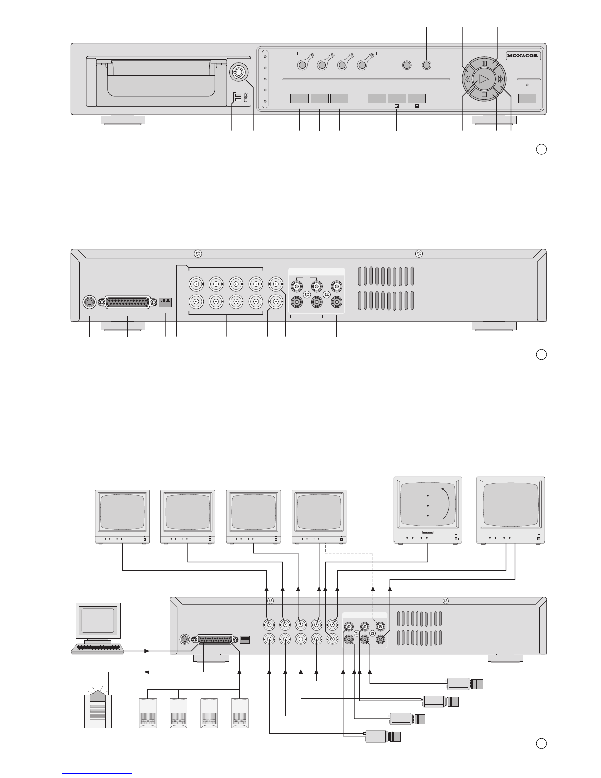
22 Impedanzumschalter für die vier Videoeingänge
INPUT (24)
HI: Der jeweilige Videoeingang ist hoch-
ohmig; erforderlich, wenn ein weiteres
Gerät am darüber liegenden Videoaus-
gang LOOP (23) angeschlossen ist
75Ω: Der jeweilige Videoeingang ist mit 75Ω
abgeschlossen; erforderlich, wenn kein
Gerät am darüber liegenden Videoaus-
gang angeschlossen ist
23 BNC-Ausgangsbuchsen LOOP 1–4 zum Her-
ausführen der durchgeschleiften Signale der Ka-
mera-Eingangsbuchsen (24)
24 BNC-Eingangsbuchsen INPUT 1–4 zum An-
schluss an die Videoausgänge der Kameras
25 BNC-Ausgangsbuchse CALL zum Anschluss an
den Videoeingang eines Nebenmonitors; der
Nebenmonitor zeigt die Kamerabilder im Vollbild-
Format mit automatischer Bildweiterschaltung
26 BNC-Ausgangsbuchse MAIN zum Anschluss an
den Videoeingang des Hauptmonitors; über den
Hauptmonitor können die Kamerabilder im Live-
und im Wiedergabebetrieb in verschiedenen
Bildformaten angezeigt (siehe Kap. 6.1) und das
Bildschirm-Menü eingeblendet werden
27 Audioeingänge 1–4 (Cinch-Buchsen) zum An-
schluss an 4 Audioquellen (z.B. Audioausgänge
der verwendeten Kameras oder Mikrofonvorver-
stärker von separat aufgestellten Mikrofonen)
Hinweis: Es kann nur eine der vier Audioquellen
aufgezeichnet werden; den Audiokanal im Menü
SYSTEM (Kap. 9.5) auswählen.
28 Audioausgänge (Cinch-Buchsen) zumAnschluss
an den Audioeingang eines Monitors oder an
einen Line-Pegel-Eingang einer Audioanlage; an
beiden Ausgängen liegt das Signal des für die
Aufnahme ausgewählten Audiokanals an
2 Hinweise für den sicheren Gebrauch
Der Recorder und sein Netzgerät entsprechen der
EMV-Richtlinie für elektromagnetische Verträglich-
keit 89/336/EWG. Das Netzgerät entspricht zusätz-
lich der Niederspannungsrichtlinie 73/23/EWG.
Beachten Sie auch unbedingt folgende Punkte:
●Der Recorder und das Netzgerät sind nur zur Ver-
wendung im Innenbereich geeignet. Schützen Sie
die Geräte vor Tropf- und Spritzwasser, hoher
Luftfeuchtigkeit und Hitze (zulässiger Einsatztem-
peraturbereich 10–40°C).
●Stellen Sie keine mit Flüssigkeit gefüllten Gefäße,
z.B. Trinkgläser oder Vasen, auf die Geräte.
●Die im Recorder entstehende Wärme muss durch
Luftzirkulation abgegeben werden. Darum dürfen
die Lüftungsschlitze am Gehäuse nicht abgedeckt
werden.
●Stecken Sie nichts durch die Lüftungsschlitze!
Dies kann zu einem Defekt des Gerätes führen.
●Nehmen Sie den Recorder nicht in Betrieb bzw.
ziehen Sie den Netzstecker des Netzgerätes
sofort aus der Steckdose, wenn:
1. sichtbare Schäden am Netzgerät, an dessen
Netzleitung oder am Recorder vorhanden sind,
2. nach einem Sturz oder Ähnlichem der Verdacht
auf einen Defekt besteht,
3. Funktionsstörungen auftreten.
Lassen Sie die Geräte in jedem Fall in einer Fach-
werkstatt reparieren.
●Ziehen Sie den Netzstecker des Netzgerätes nie
an der Zuleitung aus der Steckdose, fassen Sie
immer am Stecker an.
●Verwenden Sie zum Reinigen nur ein trockenes
weiches Tuch, niemals Chemikalien oder Wasser.
●Wird der Recorder oder das Netzgerät zweckent-
fremdet, falsch angeschlossen bzw. bedient oder
nicht fachgerecht repariert, kann keine Haftung für
daraus resultierende Sach- oder Personenschä-
den und keine Garantie für das Gerät übernom-
men werden.
●Sollen der Recorder und das Netzgerät endgültig
aus dem Betrieb genommen werden, übergeben
Sie die Geräte zur umweltfreundlichen Entsor-
gung einem örtlichen Recyclingbetrieb.
3 Anwendungsmöglichkeiten
Der DMR-408A ist ein digitaler 4-Kanal-Multiplex-
recorder und speziell für den Einsatz in Video-Über-
wachungsanlagen konzipiert. Er ist eine Kombina-
tion aus einem Digital-Recorder und einem
4-Kanal-Multiplexer. Die integrierte 80-GB-Fest-
platte reicht für Aufnahmen von bis zu ca. 1350
Stunden. Bei eingeschaltetem Überschreibmodus
ist ein Endlosbetrieb möglich.
Der Recorder bietet u.a. folgende Funktionen:
– Aufzeichnung von 4 Kameras
– 6Aufnahmegeschwindigkeiten: 1–18 Bilder/Sek.
– Audioaufzeichnung für einen Kanal
– 4 Aufnahmequalitäten: Best, High, Normal, Basic
– 4Aufnahmemodi: manuelle, timergesteuerte,
durch ein Alarmsignal oder durch den Bewe-
gungsdetektor ausgelöste Aufzeichnung
– Bewegungsdetektor für jeden Kamerakanal
unterschiedlich aktivierbar
– schnelle Suche einer Aufnahme über Zeitangabe
– Live-Überwachung in verschiedenen Anzeigefor-
maten ohne Beeinflussung einer Aufnahme
– Passwortschutz und Bediensperre
– Ereignisse während einer Aufnahme, wie z.B.
Bildverlust oder Stromunterbrechung, werden in
einer Liste protokolliert
– 4 Alarmeingänge, 1 Alarmausgang
– RS-232- und RS-485-Schnittstelle zur Fernsteue-
rung des Gerätes über Computer oder Terminal
Achtung! Das Netzgerät wird mit lebensgefähr-
licher Netzspannung versorgt. Nehmen Sie des-
halb nie selbst Eingriffe in diesem Gerät vor. Durch
unsachgemäßes Vorgehen besteht die Gefahr
eines elektrischen Schlages. Außerdem erlischt
beim Öffnen des Netzgeräts oder des Recorders
jeglicher Garantieanspruch.
pin 23: RS-232 interface: RX
pin 24: RS-485 interface: B
pin 25: alarm output: common connection
(COM) of the relay
22 Impedance selector switch for the four video
inputs INPUT (24)
HI: the respective video input is of high im-
pedance; required if another unit is con-
nected to the video output LOOP (23)
located above
75Ω: the respective video input is terminated
with 75Ω; required if no unit is connected
to the video output located above
23 BNC output jacks LOOP 1–4 for routing out the
fed-through signals of the camera input jacks
(24)
24 BNC input jacks INPUT 1–4 for connection to
the video outputs of the cameras
25 BNC output jack CALL for connection to the
video input of an auxiliary monitor; the auxiliary
monitor shows the camera pictures in the full
screen format with automatic sequential switch-
ing of pictures
26 BNC output jack MAIN for connection to the
video input of the main monitor; via the main
monitor the camera pictures can be displayed
during the live mode and replay mode in different
picture formats (see chapter 6.1) and the on-
screen menu can be inserted
27 Audio inputs 1–4 (phono jacks) for connection
to 4 audio sources (e.g. audio outputs of the
cameras used or microphone preamplifiers of
microphones placed separately)
Note: Only one of the four audio sources can be
recorded; select the audio channel in the menu
SYSTEM (chapter 9.5).
28 Audio outputs (phono jacks) for connection to the
audio input of a monitor or to a line level input of
an audio system; at both outputs the signal of the
audio channel selected for the recording is pres-
ent.
2 Safety Notes
The recorder and its power supply unit correspond
to the directive 89/336/EEC for electromagnetic
compatibility. The power supply unit additionally cor-
responds to the low voltage directive 73/23/EEC.
It is essential to observe the following items:
●The recorder and the power supply unit are suita-
ble for indoor use only. Protect the units against
dripping water and splash water, high air humidity,
and heat (admissible ambient temperature range
0–40°C).
●Do not place any vessels filled with liquid, e.g. a
drinking glass or a vase, on the units.
●The heat being generated in the recorder has to
be removed via air circulation. Therefore, the air
vents at the housing must not be covered.
●Do not insert or drop anything into the air vents!
This could lead to a defect of the unit.
●Do not set the recorder into operation, and imme-
diately disconnect the mains plug of the power
supply unit from the mains socket if
1. there is visible damage to the power supply
unit, to its mains cable, or to the recorder,
2. a defect might have occurred after a drop or
similar accident,
3. there are malfunctions.
The units must in any case be repaired by skilled
personnel.
●Never pull the mains cable to disconnect the
mains plug of the power supply unit from the
mains socket, always seize the plug!
●For cleaning only use a dry, soft cloth, by no
means chemicals or water.
●If the recorder or the power supply unit is used for
purposes other than originally intended, if it is not
correctly connected or operated, or not repaired in
an expert way, there is no liability for any resulting
personal damage or material damage and no
guarantee claims for the unit will be accepted.
●If the recorder and the power supply unit are to be
put out of operation definitively, take them to a
local recycling plant for disposal which is not
harmful to the environment.
●Important for U.K. Customers!
The wires in the mains lead of the power supply
unit are coloured in accordance with the following
code:
green/yellow = earth
blue = neutral
brown = live
As the colours of the wires in the mains lead of this
appliance may not correspond with the coloured
markings identifying the terminals in your plug,
proceed as follows:
1. The wire which is coloured green and yellow
must be connected to the terminal in the plug
which is marked with the letter Eor by the earth
symbol , or coloured green or green and
yellow.
2. The wire which is coloured blue must be con-
nected to the terminal which is marked with the
letter Nor coloured black.
3. The wire which is coloured brown must be con-
nected to the terminal which is marked with the
letter Lor coloured red.
Warning – This appliance must be earthed.
3 Applications
The DMR-408A is a digital 4-channel multiplex
recorder specially designed for applications in video
surveillance systems. It is a combination of a digital
recorder and a 4-channel multiplexer. The integrat-
ed 80GB hard disk is sufficient for recordings of up
to 1350 hours approx. With activated overwrite
mode, a continuous operation is possible.
Attention!The power supply unit is supplied with
hazardous mains voltage. Leave servicing to
skilled personnel only. Inexpert handling may
cause an electric shock hazard. Furthermore, any
guarantee claim will expire if the power supply unit
or the recorder has been opened.
6
GB
D
A
CH

4 Geräte anschließen
Vor dem Anschließen von Geräten bzw. vor dem
Ändern bestehender Anschlüsse den DMR-408A
ausschalten.
DieAbbildung 3 zeigt die möglichen Anschlüsse, die
jedoch nicht alle genutzt werden müssen:
Die Video- und Audiosignale von vier Kameras wer-
den auf den DMR-408A gegeben. Zusätzlich zum
Haupt- und Nebenmonitor sind vier weitere Monitore
zur Überwachung der einzelnen Kamerakanäle
angeschlossen. Über die 25-polige Sub-D-Buchse
wird der DMR-408Aper Computer ferngesteuert. An
die Alarmeingänge der Buchse sind 4 Alarmsen-
soren angeschlossen und der Alarmausgang ist mit
einem Alarmgeber verbunden.
4.1 Video- und Audio-Eingänge
An die BNC-Buchsen INPUT (24) die Videoaus-
gänge der Kameras anschließen. Für jeden der Ein-
gänge den zugehörigen Impedanzschalter (22) in
die entsprechende Position stellen:
HI wenn ein weiteres Gerät am darüber liegen-
den Videoausgang LOOP(23) angeschlossen
ist. Der jeweilige Videoeingang ist dann hoch-
ohmig.
75Ωwenn kein Gerät am darüber liegenden Video-
ausgang angeschlossen ist. Der entspre-
chende Videoeingang wird mit 75Ωabge-
schlossen.
Zur Tonaufzeichnung verfügt der Recorder über vier
Cinch-Eingangsbuchsen AUDIO IN (27). An die Au-
dioeingänge können z.B. die Audioausgänge von
Kameras mit integrierten Mikrofonen angeschlossen
werden oder die Vorverstärker von separat aufge-
stellten Mikrofonen. Im Bildschirm-Menü wird einge-
stellt, welcher der vier Audiokanäle aufgezeichnet
bzw. wiedergegeben werden soll (siehe Einstellung
AUDIO INPUT im Menü SYSTEM, Kap. 9.5).
4.2 Video- und Audio-Ausgänge
Den Videoeingang des (Haupt-)Monitors für die
Live-Überwachung in verschiedenen Anzeigeforma-
ten an die Buchse MAIN (26) anschließen. Über die-
sen Monitor werden auch die Bildaufzeichnungen
wiedergegeben und das Bildschirm-Menü angezeigt.
Zum zusätzlichen Betrachten aller Kamerabilder
im Vollbild-Format mit Bildweiterschaltung lässt sich
ein zweiter Monitor an die Buchse CALL (25) an-
schließen. Nicht benutzte Kanäle werden bei der
Bildweiterschaltung übersprungen.
Sollen an weiteren Überwachungsplätzen Kame-
rabilder ständig im Vollbild-Format angezeigt wer-
den, lassen sich an die Buchsen LOOP 1 bis 4 (23)
zusätzliche Monitore anschließen. Alternativ kann
an diese Buchsen auch ein Multiplexer für einen
weiteren Überwachungsplatz angeschlossen wer-
den.
Für die Tonwiedergabe steht an den beiden
Cinch-Buchsen AUDIO OUT (28) das Signal des für
die Aufnahme ausgewählten Audiokanals zur Verfü-
gung. Der Ton kann über einen Monitor mit integrier-
tem Lautsprecher oder über eine Audioanlage wie-
dergegeben werden. Die Ausgänge mit je einem
Audioeingang von max. zwei Monitoren bzw. mit
den Line-Eingängen der Audioanlage verbinden.
4.3 Alarm- und Steueranschlüsse
Über die 25-polige Sub-D-Buchse EXTERNAL I/O
(21) bietet das Gerät vier Alarmeingänge, einen
Alarmausgang sowie Schnittstellen zur Fernsteue-
rung über einen Computer bzw. ein Terminal. Für
den Anschluss liegt dem Recorder ein 25-poliger
Stecker bei.
➄Sub-D-Buchse (Ansicht der Buchsenseite)
4.3.1 Alarmeingänge
Als Alarmsensoren können z.B. Bewegungssen-
soren oder Lichtschranken eingesetzt werden, die
mit einem 5-V-TTL-Ausgang, Schließer (NO) oder
Öffner (NC) ausgestattet sind. Die Sensoren jeweils
an Masse (Pin 1) und an die folgenden Kontakte
anschließen:
Sensor für Kanal 1 an Kontakt 18
Sensor für Kanal 2 an Kontakt 5
Sensor für Kanal 3 an Kontakt 17
Sensor für Kanal 4 an Kontakt 4
Die Polarität des TTL-Alarmsignals (High oder Low)
bzw. der Kontakttyp (NO oder NC) muss für jeden
Kanal separat im Bildschirm-Menü eingestellt wer-
den (siehe Spalte ALARM im Menü CAMERA, Kap.
9.4). Vom Hersteller istAlarmauslösung durch einen
Low-Pegel bzw. Schließer (NO) voreingestellt.
4.3.2 Alarmausgang
Als potentialfreierAlarmausgang steht ein Relais mit
Schließer (NO) zur Verfügung (Kontakte 13 und 25).
Das Relais erlaubt das Schalten von ohmschen
Lasten bei max. 12V /500mA. An den Alarmaus-
gang kann z.B. ein akustischer oder optischer
Alarmgeber angeschlossen werden.
4.3.3 Anschluss eines Computers/Terminals
Über die RS-232- oder die RS-485-Schnittstelle
lässt sich der Recorder mit einem Computer oder
Terminal fernsteuern. Der DMR-408A ist dabei nur
Datenempfänger, kann also keine Daten wie
Rückmeldungen senden. Die Codierung der einzel-
nen Funktionen ist in Kapitel 11 angegeben.
1. Bei Verwendung der RS-232-Schnittstelle Pin 23
(RX) und Pin 1 (Masse) mit dem Computer/Ter-
minal verbinden.
2. Bei Verwendung der symmetrischen RS-485-
Schnittstelle Pin 12 (A) und Pin 24 (B) mit dem
Computer/Terminal verbinden. Die Abschirmung
mit Masse (Pin 1) verbinden.
Tipp: Die Verwendung verdrillter Leitungen verrin-
gert Störeinstrahlungen.
113
25 14
The recorder offers e.g. the following functions:
– recording of 4 cameras
– 6 recording speeds: 1–18 pictures/sec.
– audio recording for one channel
– 4 recording qualities: Best, High, Normal, Basic
– 4 recording modes: manual, timer-controlled,
recording triggered by an alarm signal or by the
motion detector
– motion detector to be activated differently for
each camera channel
– fast search for a recording via time indication
– live surveillance in different display formats with-
out affecting a recording
– password protection and key lock
– incidents during a recording, e.g. video loss or
power interruption, are recorded in a list
– 4 alarm inputs, 1 alarm output
– RS-232 interface and RS-485 interface for re-
mote control of the unit via computer or terminal
4 Connecting the Units
Prior to connection of units or change of existing
connections switch off the DMR-408A.
Fig. 3 shows the possible connections, however, not
all of them have to be used:
The video and audio signals of four cameras are fed
to the DMR-408A. In addition to the main monitor
and auxiliary monitor, four further monitors are
connected for surveillance of the individual camera
channels. Via the 25-pole Sub-D jack the DMR-408A
is remote-controlled by a computer. 4 alarm sensors
are connected to the alarm inputs of the jack and the
alarm output is connected to an alarm device.
4.1 Video inputs and audio inputs
Connect the video outputs of the cameras to the
BNC jacks INPUT (24). For each of the inputs set
the respective impedance selector switch (22) to the
corresponding position:
HI if a further unit is connected to the video
output LOOP (23) located above. Then the
respective video input is of high impedance.
75Ωif no unit is connected to the video output
located above. The corresponding video
input is terminated with 75Ω.
For audio recording, the recorder has four phono
input jacks AUDIO IN (27). For example, the audio
outputs of cameras with integrated microphones or
the preamplifiers of microphones placed separately
can be connected to the audio inputs. Settings are
made in the on-screen menu which of the four audio
channels are to be recorded or replayed (see setting
AUDIO INPUT in the menu SYSTEM, chapter 9.5).
4.2 Video outputs and audio outputs
Connect the video input of the (main) monitor for live
surveillance in different display formats to the jack
MAIN (26). Via this monitor also the video recordings
are replayed and the on-screen menu is displayed.
For additional viewing of all camera pictures in
the full screen format with sequential switching of
pictures it is possible to connect a second monitor to
the jack CALL (25). During the sequential switching
of pictures channels which are not used are skipped.
For displaying camera pictures permanently in
the full screen format at further places of surveil-
lance, it is possible to connect additional monitors to
the jacks LOOP 1 to 4 (23). Alternatively it is also
possible to connect a multiplexer for another place
of surveillance to these jacks.
For audio reproduction the signal of the audio
channel selected for the recording is available at
both phono jacks AUDIO OUT (28). The sound can
be reproduced via a monitor with integrated speaker
or via an audio system. Connect the outputs to one
audio input each of two monitors as a maximum or
to the line inputs of the audio system.
4.3 Alarm and control connections
Via the 25-pole Sub-D jack EXTERNAL I/O (21) the
unit offers four alarm inputs, an alarm output, and
interfaces for remote control via a computer or a ter-
minal. For connection, a 25-pole plug is supplied
with the recorder.
➄Sub-D jack (view of the jack side)
4.3.1 Alarm inputs
As alarm sensors e.g. motion detectors or light bar-
riers can be used which are equipped with a 5V TTL
output, closing contact (NO), or opening contact
(NC). Connect the sensors to ground (pin 1) and to
the following contacts in each case:
sensor for channel 1 to contact 18
sensor for channel 2 to contact 5
sensor for channel 3 to contact 17
sensor for channel 4 to contact 4
The polarity of the TTL alarm signal (high or low) or
the contact type (NO or NC) must be set in the on-
screen menu separately for each channel (see
columnALARM in the menu CAMERA, chapter 9.4).
The alarm triggering is factory-set with a low level or
closing contact (NO).
4.3.2 Alarm output
A relay with closing contact (NO) is available as a
floating alarm output (contacts 13 and 25). The relay
allows switching of ohmic loads at max. 12V /
500mA. For example, an acoustical or optical alarm
device can be connected to the alarm output.
4.3.3 Connection of a computer/terminal
The recorder can be remote-controlled with a com-
puter or terminal via the RS-232 interface or the RS-
485 interface. The DMR-408A is only data receiver,
it is not capable of transmitting data like return mes-
sages. The coding of the individual functions is indi-
cated in chapter 11.
1. When using the RS-232 interface, connect pin 23
(RX) and pin 1 (ground) to the computer/terminal.
113
25 14
7
GB
D
A
CH

5 Inbetriebnahme
1) Das Gerät ist mit einer 80-GB-Festplatte ausge-
stattet. Um eine längere Aufnahmezeit zu erhal-
ten, lässt sich eine größere Festplatte bis zu
1000GB einsetzen – siehe dazu Kapitel 12.
2) Vor dem Einschalten überprüfen, ob der Festplat-
teneinschub (6) verriegelt ist – siehe Abb. 6. Nur
bei verriegeltem Einschub ist die Festplatte be-
triebsbereit.
➅
Schloss für den Festplatteneinschub
In Position A ist der Einschub verriegelt.
3) Nach demAnschluss aller Geräte das beiliegende
Netzgerät mit der Buchse POWER (20) verbin-
den und das Netzgerät über das mitgelieferte
Netzkabel an eine Steckdose (100–240V~/
50–60Hz) anschließen. Beim Anschluss an die
Stromversorgung gibt der interne Alarmsummer
einen Signalton ab.
Nach demAnschluss an die Stromversorgung
befindet sich das Gerät im Standby-Modus [LED
über dem Schalter POWER (19) leuchtet rot].
4) Den Recorder mit dem Schalter POWER (19)
einschalten. Die Initialisierung des Geräts startet:
Alle LEDs der LED-Reihe (9) und der Ziffern-
tasten (1) leuchten kurz auf. Auf dem Bildschirm
des Hauptmonitors erscheint die Meldung HDD
DETECTING, gefolgt von MASTER HDD CON-
NECTED.
Erscheint jedoch die Meldung PLEASE IN-
SERT HDD AND LOCK THE KEY, ist die Fest-
platte nicht richtig installiert oder der Einschub
nicht verriegelt.
5) Nach der Initialisierung ist der Recorder betriebs-
bereit. Dies wird durch grünes Leuchten der LED
über dem Schalter POWER signalisiert. Die
grüne Betriebsanzeige (7) für den Festplattenein-
schub leuchtet.
In der LED-Reihe (9) leuchtet die Anzeige
TIMER, wenn die Timer-Funktion eingeschaltet
ist (siehe Kap. 9.2, Einstellung TIMER ENABLE
im Menü TIMER) und die Anzeige ALARM, wenn
die Funktion „externerAlarm“ für einen oder meh-
rere Kamerakanäle aktiviert ist (siehe Kap. 9.4,
Einstellung ALARM im Menü CAMERA).
6) Der Recorder muss über ein Bildschirm-Menü
auf die Bedürfnisse der jeweiligen Anwendung
programmiert werden. Um die Einstellungen vor-
zunehmen, siehe Kapitel 9.
7) Zum Ausschalten den Schalter POWER drücken.
Der interne Alarmsummer gibt dann einen Sig-
nalton ab und die LED über dem Schalter wech-
selt wieder auf Rot.
Ist die Überwachungsanlage längere Zeit
nicht in Betrieb, das Netzgerät vom Netz trennen,
weil sowohl der Recorder als auch das Netzgerät
einen geringen Strom verbrauchen, selbst wenn
der Recorder ausgeschaltet ist.
5.1 Bedientasten sperren
Die Bedientasten können gesperrt werden, um zu
verhindern, dass Unbefugte Einstellungen am Gerät
vornehmen.
1) Zum Sperren der Bedientasten die beiden Tasten
MENU (10) und ENTER (11) gleichzeitig drü-
cken. Auf dem Bildschirm erscheint die Meldung
KEY LOCKED und erlischt dann wieder.
2) Zum Aufheben der Sperrung die Tasten MENU
und ENTER erneut gleichzeitig drücken. Nach
dem Drücken der Tasten wird das 4-stellige
Passwort abgefragt: Das Passwort eingeben
(siehe unter „Aufrufen des Bildschirm-Menüs“ am
Anfang des Kap. 9) und mit der Taste ENTER
bestätigen. Auf dem Bildschirm wird KEY UN-
LOCKED eingeblendet und erlischt dann wieder.
6 Live-Überwachung
Die Live-Überwachung der aktuellen Kamerabilder
ist über folgende Monitore möglich:
1. Über den Hauptmonitor an der Buchse MAIN
(26); für diesen Monitor lassen sich verschiedene
Anzeigeformate auswählen, siehe dazu Kap. 6.1.
2. Über einen an der Buchse CALL (25) ange-
schlossenen Nebenmonitor; dieser zeigt alle an-
geschlossenen Kamerakanäle nacheinander im
Vollbild-Format (Sequenzschaltung). Nicht be-
nutzte Kanäle werden übersprungen. Im Bild-
schirm-Menü lässt sich die Bildverweilzeit ein-
stellen (siehe Menüzeile DWELL TIME im Menü
SYSTEM, Kap. 9.5). Sie ist vom Hersteller auf
2 Sekunden voreingestellt.
3. Über an den Buchsen LOOP 1 bis 4 (23) ange-
schlossene Monitore; diese Monitore zeigen nur
das Vollbild des zugehörigen Kamerakanals.
6.1 Anzeigeformate wählen
Das für den Hauptmonitor an Buchse MAIN (26)
zuletzt gewählteAnzeigeformat wird gespeichert, so
dass nach dem Einschalten oder nach einer Strom-
unterbrechung wieder die zuletzt eingestellte Bild-
anordnung erscheint.
6.1.1 Vollbild-Format
In diesem Format erscheint das gewählte Kamera-
bild als Vollbild auf dem Monitor.
1) Die Zifferntaste (1) des gewünschten Kamera-
kanals drücken. Die LED der Taste leuchtet.
2) Zum Umschalten auf eine andere Kamera die
zugehörige Zifferntaste drücken.
6.1.2 Mehrfachbild-Formate
Soll nicht nur ein Kamerabild zur Zeit auf dem
Hauptmonitor betrachtet werden, lässt sich eines
der beiden Mehrfachbild-Formate wählen:
Taste (15) für alle vier Bilder
Der Bildschirm ist zur Darstellung aller Kamera-
kanälen in vier gleich große Sektoren unterteilt.
A
B
●Zum Schutz der Festplatte das Gerät vor dem
Trennen von der Stromversorgung zuerst über
den Schalter POWER (19) ausschalten.
●Das Gerät nicht in einem kurzen Zeitraum ein-
und ausschalten. Zwischen dem Ein- und Aus-
schalten müssen mindestens 3Sek. liegen.
2. When using the balanced RS-485 interface, con-
nect pin 12 (A) and pin 24 (B) to the computer/ter-
minal. Connect the screening to ground (pin 1).
Note: If twisted lines are used, the interference will
be reduced.
5 Setting into Operation
1) The unit is equipped with an 80GB hard disk. To
obtain a longer recording time, a larger hard disk
of up to 1000GB can be inserted – see chapter 12.
2) Prior to switching on, check if the hard disk inser-
tion (6) is locked – see fig. 6. Only with the inser-
tion locked the hard disk is ready for operation.
➅
Lock for the hard disk insertion
In position A the insertion is locked
3) After connection of all units connect the supplied
power supply unit to the jack POWER (20) and
the power supply unit via the supplied mains
cable to a socket (100–240V~/50–60Hz).
When connecting it to the power supply, the inter-
nal alarm buzzer will sound.
After connection to the power supply, the unit
is in the standby mode [LED above the POWER
switch (19) shows red].
4) Switch on the recorder with the POWER switch
(19). The initializing of the unit starts:
All LEDs of the LED row (9) and the numerical
keys (1) light up shortly. The message HDD
DETECTING is displayed on the screen of the
main monitor, followed by MASTER HDD
CONNECTED.
However, if the message PLEASE INSERT
HDDAND LOCK THE KEY is displayed, the hard
disk is not correctly installed or the insertion is not
locked.
5) After initializing, the recorder is ready for opera-
tion. This is signalized by the LED above the
POWER switch showing green. The green power
LED (7) for the hard disk insertion lights up.
The LED TIMER will light up in the LED row
(9) if the timer function has been activated (see
chapter 9.2, setting TIMER ENABLE in the menu
TIMER) as well as the LEDALARM if the function
“external alarm” has been activated for one or
several camera channels (see chapter 9.4, set-
ting ALARM in the menu CAMERA).
6) The recorder must be programmed via an on-
screen menu to the requirements of the respective
application. To make the settings, see chapter 9.
7) To switch off, press the POWER switch.Then the
internal alarm buzzer will sound and the LED
above the switch shows red again.
If the surveillance system is not in operation
for a longer time, disconnect the power supply
unit from the mains because both the recorder
and the power supply unit have a low power con-
sumption even if the recorder is switched off.
5.1 Locking of operational keys
The operational keys can be locked to prevent
unauthorized persons from making settings at the
unit.
1) To lock the operational keys, press both keys
MENU (10) and ENTER (11) at the same time.
The message KEY LOCKED is shortly displayed
on the screen.
2) To cancel the locking, press the keys MENU and
ENTER at the same time again. After pressing
the keys, the 4-digit password is requested: enter
the password (see “Calling the on-screen menu”
at the beginning of chapter 9) and confirm with
the key ENTER. KEY UNLOCKED is shortly dis-
played on the screen.
6 Live Surveillance
Live surveillance of the present camera pictures is
possible via the following monitors:
1. Via the main monitor connected to the jack MAIN
(26); it is possible to select different display for-
mats for this monitor, see chapter 6.1.
2. Via an auxiliary monitor connected to the jack
CALL (25); this monitor successively shows all
connected camera channels in the full screen for-
mat (sequential switching). Channels which are
not used are skipped. The picture dwell time can
be set in the on-screen menu (see menu line
DWELL TIME in the menu SYSTEM, chap. 9.5).
It is factory-set to 2 seconds.
3. Via monitors connected to the jacks LOOP 1 to 4
(23); these monitors only show the full screen
picture of the corresponding camera channel.
6.1 Selecting display formats
The last display format selected for the main monitor
connected to the jack MAIN (26) is memorized so
that after switching-on or after a power interruption
the picture arrangement last set will be displayed
again.
6.1.1 Full screen format
In this format the selected camera picture is dis-
played as a full screen picture on the monitor.
1) Press the numerical key (1) of the desired
camera channel. The LED of the key lights up.
2) To switch to another camera, press the corre-
sponding numerical key.
6.1.2 Multiple picture formats
For viewing more than one camera picture on the
main monitor at a time, it is possible to select one of
the two multiple picture formats:
Key (15) for all four pictures
The screen is subdivided to display all camera chan-
nels in four sectors of the same size.
A
B
●To protect the hard disk, first switch off the unit
via the POWER switch (19) prior to disconnect-
ing it from the power supply.
●Do not switch on and off the unit within a short
interval. There must be at least 3 seconds be-
tween switching on and off.
8
GB
D
A
CH

Taste (14) für das Bild-im-Bild-Format
Auf dem Bildschirm erscheint ein Kamerakanal im
Vollbild-Format und ein weiterer Kamerakanal als
eingeblendetes kleines Bild.
Zum Auswählen der Kamerakanäle für das Bild-
im-Bild-Format:
1) Die Taste ENTER (11) drücken. Die Nummer
bzw. die Bezeichnung des Kamerakanals für das
Vollbild blinkt.
2) Mit einer der Zifferntasten (1) den gewünschten
Kamerakanal auswählen.
3) Danach mit der Cursor-Taste Left (4) oder
Right (18) die Nummer bzw. die Bezeichnung
hinter dem Schrägstrich für das kleine Bild
anwählen und den Kamerakanal mit einer der
Zifferntasten auswählen.
4) Danach den Auswahlmodus durch Drücken der
Taste MENU (10) beenden.
6.1.3 Vergrößerung eines Bildausschnittes
(Zoom-Funktion)
1) Die Taste ZOOM (13) drücken. Für das Bild (ent-
weder das Vollbild oder bei dem Vierfachbild das
Bild im ersten Sektor) ist dann die Zoom-Funk-
tion aktiviert:
Ein Ausschnitt des Bildes wird vergrößert
(doppelte Breite x doppelte Höhe) auf dem Bild-
schirm gezeigt. Zusätzlich ist das Komplettbild
verkleinert eingeblendet.
2) Im verkleinerten Komplettbild ist der jeweilige
Bildausschnitt, der gerade vergrößert angezeigt
ist, durch einen Rahmen markiert. Mit der Taste
ZOOM kann ein anderer Bildausschnitt ausge-
wählt werden: Mit jedem Drücken der Taste wird
auf den nächsten Bildausschnitt gesprungen, der
dann vergrößert angezeigt wird.
3) Zum Ausschalten der Zoom-Funktion ein ande-
res Anzeigeformat (Vollbild, Bild-im-Bild oder
Vierfachbild) mit der entsprechenden Taste (1, 14
oder 15) anwählen.
7 Aufnahme
Der Recorder bietet vier Aufnahmemodi:
1. manuell gestartete Aufnahme
2. timergesteuerte Aufnahme
3. Alarmaufnahme (durch ein externes Alarmsignal
ausgelöste Aufnahme)
4. durch den internen Bewegungsdetektor ausge-
löste Aufnahme
Während einer Aufnahme leuchtet immer die Auf-
nahmeanzeige REC in der LED-Reihe (9). Fällt die
Stromversorgung während einer Aufnahme aus,
wird das aufgenommene Bild auf der Festplatte
gespeichert und das Gerät schaltet bei Wiederher-
stellung der Stromversorgung in den vorherigenAuf-
nahmemodus zurück.
Im Bild für den Hauptmonitor sind während einer
Aufnahme folgende Informationen eingeblendet:
1. Uhrzeit und Datum (entsprechend der Einstellung
TIME DISPLAY im Menü SYSTEM, Kap. 9.5)
2. den Kennbuchstaben für den Aufnahmemodus:
A bei Alarmaufnahme
D bei Aufnahme, die durch den Bewegungs-
detektor gestartet wurde
M bei manueller Aufnahme
T bei timergesteuerter Aufnahme
3. das Aufnahmesymbol ●
4. bei eingeschalteter Überschreibfunktion:
OW (= „overwrite“);
bei ausgeschalteter Überschreibfunktion:
die verbleibende Speicherkapazität der Festplat-
te, z.B. „032GB“ bei 32 Gigabyte Restspeicher-
kapazität
(Zum Ein-/Ausschalten der Überschreibfunktion
siehe Menü RECORD, Kapitel 9.3.)
7.1 Manuelle Aufnahme
Zum Starten der Aufnahme die Taste REC (3) drü-
cken. Zum Beenden der Aufnahme die Stopptaste
(17) drücken.
Für die manuelleAufnahme gelten die Einstellun-
gen der Menüzeilen REC IPS und REC QUALITY
des Menüs RECORD (siehe Kapitel 9.3).
7.2 Timergesteuerte Aufnahme
Ist die Timer-Funktion aktiviert [siehe Kap. 9.2; bei
eingeschalteter Funktion leuchtet in der LED-Reihe
(9) die Anzeige TIMER], startet und stoppt der Re-
corder automatisch zu den im Menü TIMER festge-
legten Zeiten. Durch Drücken der Stopptaste (17)
kann eineAufnahme auch vorzeitig beendet werden.
Die Aufnahmequalität und Aufnahmegeschwin-
digkeit lässt sich im Menü TIMER für jedeAufnahme
separat einstellen.
7.3 Alarmaufnahme
Ist dieAlarmfunktion aktiviert [siehe Kap. 9.4, Menü-
punktALARM; bei eingeschalteter Funktion leuchtet
in der LED-Reihe (9) dieAnzeige ALARM] und emp-
fängt der Recorder ein Alarmsignal an einem der
Alarmeingänge [Pins 4, 5, 17 und 18 der Sub-D-
Buchse EXTERNAL I/O (21)], schaltet das Gerät
auf Alarmaufnahme.
1. Falls zum Zeitpunkt des Alarms keine Aufnahme
läuft, schaltet der Recorder automatisch auf Auf-
nahme. Für die Aufnahmegeschwindigkeit und
Aufnahmequalität gelten die Einstellungen der
Menüzeilen ALARM REC IPS und ALARM REC
QUALITY des Menüs RECORD (Kapitel 9.3).
Nach dem Ablauf der Alarmdauer (Voreinstel-
lung = 10Sek, veränderbar in der Zeile ALARM
DURATION im Menü SYSTEM, siehe Kapitel 9.5)
stoppt die Aufnahme und der Recorder kehrt in
seinen vorherigen Betriebsmodus zurück.
2. Tritt ein Alarm während einer manuellen oder
timergesteuerten Aufnahme auf, so hat die
Alarmaufnahme Priorität, d.h. die Aufnahmege-
schwindigkeit und -qualität ändern sich entspre-
●Das gewählte Anzeigeformat für den Haupt-
monitor hat keinen Einfluss auf eine Aufnahme.
Es werden bei jederAufnahme immer die Kame-
rakanäle aufgezeichnet, die in der Spalte RE-
CORD des Menüs CAMERA nicht auf OFF
geschaltet sind – siehe Kapitel 9.4.
Key (14) for the picture-in-picture format
On the screen one camera channel is displayed in
the full screen format and another camera channel
as an inserted small picture.
To select the camera channels for the picture-in-
picture format:
1) Press the key ENTER (11). The number or the
designation of the camera channel for the full
screen picture flashes.
2) Select the desired camera channel with one of
the numerical keys (1).
3) Then select the number or the designation
behind the slash for the small picture with the cur-
sor key Left (4) or Right (18) and select the
camera channel with one of the numerical keys.
4) Then press the key MENU (10) to stop the selec-
tion mode.
6.1.3 Enlargement of a picture cutout
(zoom function)
1) Press the key ZOOM (13). Then the zoom func-
tion is activated for the picture (either the full
screen picture or – in case of a quad picture – the
picture in the first sector):
A cutout of the picture is displayed on the
screen in an enlarged way (double width x double
height). In addition, the complete picture is insert-
ed in reduced size.
2) In the sized-reduced complete picture the re-
spective picture cutout which is being displayed
as an enlarged picture at present is marked by a
frame. With the key ZOOM another picture cutout
can be selected: With each pressing of the key
the unit goes to the next picture cutout which will
then be displayed as an enlarged picture.
3) To switch off the zoom function, select another
display format (full screen picture, picture-in-pic-
ture, or quad picture) with the corresponding key
(1, 14, or 15).
7 Recording
The recorder offers four recording modes:
1. manual start of recording
2. timer-controlled recording
3. alarm recording (recording triggered by an exter-
nal alarm signal)
4. recording triggered by the internal motion detec-
tor
During a recording always the recording indication
REC in the LED row (9) lights up. If the power sup-
ply fails during a recording, the recorded picture will
be memorized on the hard disk and the unit will
switch back to its previous recording mode after the
power supply has been restored.
The following information is inserted in the pic-
ture for the main monitor during a recording:
1. time and date (according to the setting TIME DIS-
PLAY in the menu SYSTEM, chapter 9.5)
2. the identification letter for the recording mode:
A for alarm recording
D for recording triggered by the motion detector
M for manual recording
T for timer-controlled recording
3. the recording symbol ●
4. with activated overwrite function:
OW (= “overwrite”);
with deactivated overwrite function:
the remaining storage capacity of the hard disk,
e.g. “032GB” for a remaining storage capacity of
32 gigabytes
(For activating/deactivating the overwrite func-
tion see menu RECORD, chapter 9.3.)
7.1 Manual recording
To start the recording, press the key REC (3). To
stop the recording, press the key STOP (17).
The settings of the menu lines REC IPS and REC
QUALITY of the menu RECORD apply to the
manual recording (see chapter 9.3).
7.2 Timer-controlled recording
If the timer function is activated [see chapter 9.2;
with activated function the LED TIMER in the LED
row (9) lights up], the recorder will automatically
start and stop at the times defined in the menu
TIMER. It is also possible to stop a recording at any
time by pressing the key STOP (17).
The recording quality and the recording speed
can be set in the menu TIMER separately for each
recording.
7.3 Alarm recording
If the alarm function is activated [see chapter 9.4,
menu item ALARM; with activated function the indi-
cationALARM in the LED row (9) lights up] and if the
recorder receives an alarm signal at one of the
alarm inputs [pins 4, 5, 17, and 18 of the Sub-D jack
EXTERNAL I/0 (21)], the unit will switch to alarm
recording.
1. If no recording is made at the time of alarm, the
recorder will automatically switch to recording.
For the recording speed and recording quality the
settings of the menu lines ALARM REC IPS and
ALARM REC QUALITY of the menu RECORD
apply (chapter 9.3).
After the alarm duration has elapsed (preset-
ting = 10 seconds, it can be changed in the line
ALARM DURATION in the menu SYSTEM, see
chapter 9.5), the recording will stop and the re-
corder will return to its previous operating mode.
2. If an alarm occurs during a manual or timer-con-
trolled recording, the alarm recording takes prior-
ity, i.e. the recording speed and the recording
quality change according to the settings in the
menu lines ALARM REC IPS and ALARM REC
●The selected display format for the main monitor
does not affect a recording. During each record-
ing always the camera channels are registered
which are not set to OFF in the column RECORD
of the menu CAMERA – see chapter 9.4.
9
GB
D
A
CH

chend den Einstellungen der MenüzeilenALARM
REC IPS und ALARM REC QUALITY. Nach
Ablauf der Alarmdauer schaltet der Recorder in
den vorherigen Aufnahmemodus zurück.
3. Wird zum Zeitpunkt eines Alarms gerade eine
Aufzeichnung abgespielt, erfolgt keineAufnahme.
Durch Drücken der Stopptaste (17) kann eine
Alarmaufnahme auch vorzeitig beendet werden.
Weitere Informationen zu den Vorgängen im Alarm-
fall sind im Kapitel 10.1 angegeben.
7.4 Aufnahmestart durch den Bewegungs-
detektor
Ist der Bewegungsdetektor aktiviert (siehe Kapitel
9.4.1) und im Menü RECORD die Funktion MOTION
TRIGGER RECORD auf ON gestellt (siehe Kapitel
9.3), schaltet das Gerät bei einer erkannten Bewe-
gung auf Alarmaufnahme.
1. Falls zum Zeitpunkt des Alarms keine Aufnahme
läuft, schaltet der Recorder automatisch auf Auf-
nahme. Für die Aufnahmegeschwindigkeit und
Aufnahmequalität gelten die Einstellungen der
Menüzeilen ALARM REC IPS und ALARM REC
QUALITY des Menüs RECORD (Kapitel 9.3).
Nach dem Ablauf der Alarmdauer stoppt die
Aufnahme und der Recorder kehrt in seinen vor-
herigen Betriebsmodus zurück.
2. Tritt ein Alarm während einer manuellen oder
timergesteuerten Aufnahme auf, so hat die
Alarmaufnahme Priorität, d.h. die Aufnahmege-
schwindigkeit und -qualität ändern sich entspre-
chend den Einstellungen der MenüzeilenALARM
REC IPS und ALARM REC QUALITY. Nach
Ablauf der Alarmdauer schaltet der Recorder in
den vorherigen Aufnahmemodus zurück.
3. Wird zum Zeitpunkt der erkannten Bewegung
gerade eine Aufzeichnung abgespielt, erfolgt
keine Aufnahme.
Durch Drücken der Stopptaste (17) kann dieAuf-
nahme auch vorzeitig beendet werden. Weitere
Informationen zu den Vorgängen im Alarmfall sind
im Kapitel 10.3 angegeben.
8 Wiedergabe
1) Zur Wiedergabe der letzten Aufzeichnung die
Starttaste (16) drücken. (Zur Wiedergabe einer
anderen Aufzeichnung siehe Kapitel 8.4.) Die
Wiedergabe beginnt ab dem Startpunkt der Auf-
zeichnung. Auf dem Bildschirm erscheint das
Symbol und in der LED-Reihe (9) leuchtet die
Anzeige PLAY. Ist das Ende der Aufzeichnung
erreicht, wird END eingeblendet.
2) Während der Wiedergabe lässt sich:
a mit den Zifferntasten (1) ein bestimmtes Ka-
merabild als Vollbild anzeigen
b mit der Taste ZOOM (13) ein Vollbild ver-
größern (siehe auch Kapitel 6.1.3)
c mit der Taste (14) das Bild-im-Bild-Format
wählen (siehe auch Kapitel 6.1.2)
d mit der Taste (15) alle vier Kamerakanäle
anzeigen
3) Soll die Wiedergabe rückwärts ablaufen, während
der Wiedergabe die Taste (4) drücken.Auf dem
Bildschirm erscheint das Symbol . Zum Zurück-
schalten auf Vorlauf die Starttaste drücken.
4) Um auf Standbild zu schalten, die Pausentaste
(5) drücken.Auf dem Bildschirm erscheint das
Symbol . Zum Weiterlaufen der Wiedergabe die
Starttaste oder die Pausentaste drücken.
5) Zum Stoppen der Wiedergabe die Stopptaste
(17) drücken.
8.1 Schneller Vor-/Rücklauf
Währendder Wiedergabe im Vor-oderRücklauf kann
auf 2fache, 4fache, 8fache, 16fache oder 32fache
Wiedergabegeschwindigkeit geschaltet werden.
1) Mit der Taste (18) die Vorlaufgeschwindigkeit
erhöhen bzw. mit der Taste (4) die Rücklauf-
geschwindigkeit: Mit jedem Druck der entspre-
chenden Taste wird die jeweils nächste Geschwin-
digkeit angewählt. Die gewählte Geschwindigkeit
wird auf dem Bildschirm angezeigt, z.B. „ x8“
bei 8facher Vorlaufgeschwindigkeit oder „ x2“
bei doppelter Rücklaufgeschwindigkeit.
2) Zum Zurückschalten vom schnellen Vorlauf auf
Wiedergabe in Normalgeschwindigkeit die Start-
taste (16) drücken.
Zum Zurückschalten vom schnellen Rücklauf
auf Rücklauf in Normalgeschwindigkeit die Taste
so oft drücken, bis wieder auf dem Bild-
schirm angezeigt wird.
8.2 Langsamer Vor-/Rücklauf
Während der Wiedergabe im Vor- oder Rücklauf
kann auf 1/2fache, 1/4fache, 1/8fache, 1/16fache oder
1/32fache Wiedergabegeschwindigkeit geschaltet
werden.
1) Während der Wiedergabe zuerst die Taste
SLOW (2) drücken.
2) Mit der Vorlauf-Taste (18) oder mit der Rück-
lauf-Taste (4) die Geschwindigkeit anwählen:
Mit jedem Druck der entsprechenden Taste wird
die jeweils nächste Geschwindigkeit angewählt.
Die gewählte Geschwindigkeit wird auf dem Bild-
schirm angezeigt, z.B. „ x1/8“ bei Reduzierung
der Vorlaufgeschwindigkeit auf 1/8, oder „ x1/2“
bei halber Rücklaufgeschwindigkeit.
3) Zum Zurückschalten vom langsamen Vorlauf auf
Wiedergabe in Normalgeschwindigkeit die Start-
taste (16) drücken.
Zum Zurückschalten vom langsamen Rück-
lauf auf Rücklauf in Normalgeschwindigkeit zu-
erst die Starttaste , dann einmal die Taste
drücken.
8.3 Schrittweise Wiedergabe von
Einzelbildern im Pausenmodus
1) Während der Wiedergabe den Recorder mit der
Pausentaste (5) auf Standbild schalten.
2) Mit der Vorlauf-Taste (18) und der Rücklauf-
Taste (4) können die Einzelbilder der Auf-
nahme Schritt für Schritt angezeigt werden:
Mit jedem Druck der Taste wird auf das
nächste Einzelbild geschaltet. Wird die Taste
gedrückt gehalten, laufen die Einzelbilder nach-
einander durch.
QUALITY. After the alarm duration has elapsed,
the recorder switches back to its previous record-
ing mode.
3. If a recording is being replayed at the time of an
alarm, no recording will be made.
It is also possible to stop an alarm recording at any
time by pressing the key STOP (17). Further
information on the proceedings in case of alarm is
given in chapter 10.1.
7.4 Recording start by the motion detector
If the motion detector is activated (see chapter
9.4.1) and the function MOTION TRIGGER REC-
ORD is set to ON in the menu RECORD (see chap-
ter 9.3), the unit will switch to alarm recording in
case of a recognized movement.
1. If no recording is made at the time of the alarm,
the recorder will automatically switch to record-
ing. For the recording speed and the recording
quality the settings of the menu lines ALARM
REC IPS and ALARM REC QUALITY of the
menu RECORD apply (chapter 9.3).
After the alarm duration has elapsed, the
recording stops and the recorder returns to its
previous operating mode.
2. If an alarm occurs during a manual or timer-con-
trolled recording, the alarm recording takes prior-
ity, i.e. the recording speed and recording quality
change according to the settings of the menu
lines ALARM REC IPS and ALARM REC QUAL-
ITY. After the alarm duration has elapsed, the
recorder switches back to its previous recording
mode.
3. If a recording is being replayed at the time of the
recognized movement, no recording will be
made.
It is also possible to stop the recording at any time
by pressing the key STOP (17). Further informa-
tion on the proceedings in case of alarm is given in
chapter 10.3.
8 Replay
1) To replay the last recording, press the start key
(16). (To replay another recording, see chap-
ter 8.4.) The replay starts from the starting point
of the recording. The symbol is displayed on
the screen and the LED PLAY in the LED row (9)
lights up. If the end of the recording is reached,
END is inserted.
2) During the replay it is possible
a to display a defined camera picture as a full
screen picture with the numerical keys (1)
b to enlarge a full screen picture with the key
ZOOM (13) [also see chapter 6.1.3]
c to select the picture-in-picture format with the
key (14) [also see chapter 6.1.2]
d to display all four camera channels with the
key (15)
3) For rewind replay, press the key (4) while
replaying. The symbol is displayed on the
screen. To switch back to forward replay, press
the start key .
4) To switch to still picture, press the pause key
(5). The symbol is displayed on the screen. To
continue the replay, press the start key or the
pause key .
5) To stop the replay, press the key STOP (17).
8.1 Fast forward/rewind
During the replay in forward or rewind the recorder
can be set to different replay speeds: double, 4-fold,
8-fold, 16-fold, or 32-fold.
1) The forward speed is increased with the key
(18) and the rewind speed with the key (4):
with each pressing of the corresponding key, the
next higher speed is selected in each case. The
selected speed is displayed on the screen, e.g.
“ x8” in case of 8-fold forward speed or “ x2” in
case of double rewind speed.
2) To switch back from fast forward to replay at nor-
mal speed, press the start button (16).
To switch back from fast rewind to rewind at
normal speed, press the key so many times
until is again displayed on the screen.
8.2 Slow forward/rewind
During the replay in forward or rewind the recorder
can be set to different replay speeds: 1/2, 1/4, 1/8,
1/16, or 1/32.
1) During the replay first press the key SLOW (2).
2) Select the speed with the forward key (18)
or the rewind key (4): with each pressing
of the corresponding key the next speed is se-
lected in each case. The selected speed is dis-
played on the screen, e.g. “ x1/8” if the forward
speed is reduced to 1/8, or “ x1/2” at half rewind
speed.
3) To switch back from slow rewind to replay at nor-
mal speed, press the start key (16).
To switch back from slow rewind to rewind at
normal speed, first press the start key , then
the key once.
8.3 Stepwise replay of individual pictures in
the pause mode
1) During the replay switch the recorder to still pic-
ture by pressing the pause key (5).
2) With the forward key (18) and the rewind key
(4) the individual pictures of the recording can
be displayed step by step:
With each pressing of the key the unit
switches to the next individual picture. If the key
is kept pressed, the individual pictures are suc-
cessively run through.
With each pressing of the key , the unit
switches to the previous individual picture. If the
key is kept pressed, the individual pictures are
run through in rewind order.
10
GB
D
A
CH

Mit jedem Druck der Taste wird auf das
vorherige Einzelbild geschaltet. Wird die Taste
gedrückt gehalten, laufen die Einzelbilder nach-
einander rückwärts durch.
3) Zum Beenden der Einzelbildwiedergabe die Start-
taste oder die Pausentaste drücken.
8.4 Bestimmte Aufnahme suchen und ab-
spielen
Anhand eines Suchmenüs kann aus allen Aufzeich-
nungen gezielt eine bestimmte Aufzeichnung aus-
gewählt und wiedergegeben werden.
1) Die Taste SEARCH (12) drücken. Auf dem Bild-
schirm erscheint das Suchmenü:
2) Mit den Cursor-Tasten Up (5) und Down (17) kön-
nen die 5 Untermenüs des Suchmenüs ange-
wählt und mit der Taste ENTER (11) aufgerufen
werden.
3) Zum Verlassen des Suchmenüs die Taste MENU
(10) drücken.
Hinweise:
a Während einer Aufnahme ist die Taste SEARCH
gesperrt.
b Sind noch keine Aufnahmen gemacht worden,
erscheint beim Aufrufen des Suchmenüs für ca.
10Sek. die Einblendung DISK EMPTY. Die Mel-
dung kann durch Drücken der Taste STOP
(17) auch sofort ausgeblendet werden.
8.4.1 LAST RECORD
Wiedergabe der letzten Aufnahme
Wird LAST RECORD mit der Taste ENTER (11) auf-
gerufen, schaltet der Recorder auf Wiedergabe der
Aufzeichnung, die zuletzt vorgenommen wurde.
8.4.2 FULL LIST
Gesamtliste aller Aufnahmen
Wird FULL LIST mit der Taste ENTER (11) aufgeru-
fen, erscheint auf dem Bildschirm eine Liste sämt-
licher Aufnahmen, z. B.:
Die Aufzeichnungen sind nach dem Zeitpunkt des
Aufnahmestarts sortiert. Zusätzlich zur Datums- und
Zeitangabe ist jede Aufzeichnung mit einem Kenn-
buchstaben für den Aufnahmemodus versehen:
A: Alarmaufnahme
D: durch den Bewegungsdetektor gestartete Auf-
name
M: manuelle Aufnahme
T: timergesteuerte Aufnahme
Die Abkürzung M-HDD steht für Master Hard Disk
Drive = Hauptfestplattenlaufwerk.
1) Auf einer Menüseite werden max. 8Aufzeichnun-
gen aufgelistet. Mit der Cursor-Taste Left (4)
lässt sich die Liste „zurückblättern“, um länger zu-
rückliegende Aufzeichnungen zu finden und mit
derCursor-Taste Right(18) kann wieder auf die
jüngsten Aufzeichnungen „vorgeblättert“ werden.
2) Soll die Menüseite ohne Auswahl einer Auf-
nahme wieder verlassen werden, die Taste
MENU (10) drücken.
3) Zum Auswählen einerAufzeichnung diese mit der
Cursor-Taste Up (5) oder Down (17) anwählen
und sie mit der Taste ENTER oder der Starttaste
(16) aufrufen: Die Wiedergabe beginnt ab
dem Startpunkt der ausgewählten Aufzeichnung
und läuft – wenn sie nicht vorzeitig mit der Taste
STOP (17) gestoppt wird – ununterbrochen
bis zum Endpunkt der letzten Aufzeichnung.
8.4.3 ALARM LIST
Liste aller Alarmaufnahmen
Um nur die Alarmaufnahmen aufzulisten, die Zeile
ALARM LIST anwählen und die Liste mit der Taste
ENTER (11) aufrufen:
Die Aufzeichnungen sind nach dem Zeitpunkt des
Aufnahmestarts sortiert. Zusätzlich zur Datums- und
Zeitangabe sind die Aufzeichnung mit dem Kenn-
buchstaben „A“ für „Alarmaufnahme“ versehen.
1) Die Auswahl einer Aufzeichnung erfolgt wie bei
der Gesamtliste mit den Cursor-Tasten Right
(18) und Left (4) zum Vor- und Rückblättern
sowie den Cursor-Tasten Up (5) und Down (17)
zum Anwählen der Aufzeichnung.
2) Nach der Auswahl die Wiedergabe mit der Start-
taste oder der Taste ENTER starten: Die Wie-
dergabe beginnt ab dem Startpunkt der ausge-
wählten Alarmaufzeichnung und läuft – wenn sie
nicht vorzeitig mit der Taste STOP (17) ge-
stoppt wird – ununterbrochen bis zum Endpunkt
der letzten Aufzeichnung. Dabei werden nicht nur
die Alarmaufnahmen durchlaufen, sondern alle
Aufnahmen, die nach der ausgewählten Alarm-
aufnahme aufgezeichnet wurden.
8.4.4 MOTION LIST
Liste der detektorgestarteten Aufnahmen
Um nur die Aufnahmen aufzulisten, die durch den
Bewegungsdetektor gestartet wurden, im Such-
menü die Zeile MOTION LIST anwählen und die
Liste mit der Taste ENTER (11) aufrufen. Jede Auf-
zeichnung ist am Zeilenanfang mit einem „D“ für De-
tektor gekennzeichnet. Die weitere Auswahl erfolgt
wie bei der Liste allerAlarmaufnahmen (Kap. 8.4.3).
A 26-SEP-2003 23:05:58 M-HDD
A 26-SEP-2003 01:58:52 M-HDD
A 20-SEP-2003 04:59:32 M-HDD
A 13-SEP-2003 05:03:00 M-HDD
A 09-SEP-2003 22:36:29 M-HDD
A 01-SEP-2003 00:07:04 M-HDD
A 29-AUG-2003 02:43:02 M-HDD
A 22-AUG-2003 04:12:33 M-HDD
:PAGE UP :PAGE DOWN
D 26-SEP-2003 23:05:58 M-HDD
T 26-SEP-2003 08:00:00 M-HDD
M 26-SEP-2003 06:45:20 M-HDD
A 26-SEP-2003 01:58:52 M-HDD
T 25-SEP-2003 08:00:00 M-HDD
T 24-SEP-2003 08:00:00 M-HDD
D 23-SEP-2003 07:30:21 M-HDD
A 22-SEP-2003 17:01:38 M-HDD
:PAGE UP :PAGE DOWN
(SEARCH)
LAST RECORD
ULL LIST
ALARM LIST
MOTION LIST
TIME SEARCH
3) To stop the individual picture replay, either press
the start key or the pause key .
8.4 Searching and replaying a certain re-
cording
By means of the search menu it is possible to select
a certain recording from all recordings in a purpose-
ful way and to replay it.
1) Press the key SEARCH (12). The search menu is
displayed:
2) With the cursor keys Up (5) and Down (17) the
5 submenus of the search menu can be selected
and called with the key ENTER (11).
3) To exit the search menu, press the key MENU
(10).
Notes:
a During a recording the key SEARCH is locked.
b If no recordings have been made yet, the mes-
sage DISK EMPTY is inserted for approx. 10 sec-
onds when calling the search menu. It is also
possible to extinguish the message immediately
by pressing the key STOP (17).
8.4.1 LAST RECORD
Replay of the last recording
If LAST RECORD is called with the key ENTER (11),
the recorder switches to replay of the last record-
ing.
8.4.2 FULL LIST
Total list of all recordings
If FULLLIST is called with the key ENTER (11), a list
of all recordings is displayed on the screen, e.g.:
The recordings are sorted according to the time of
the recording start. In addition to the time/date indi-
cation each recording is provided with an identifica-
tion letter for the recording mode:
A: alarm recording
D: recording started by the motion detector
M: manual recording
T: timer-controlled recording
The abbreviation M-HDD stands for Master Hard
Disk Drive
1) 8 recordings as a maximum are listed on a menu
page. With the cursor key Left (4) it is possible
to go back in the list to find recordings made at an
earlier date, and with the cursor key Right (18)
it is possible to go forward to the latest recordings
again.
2) To exit the menu without selection of a recording,
press the key MENU (10).
3) To select a recording, use the cursor key Up (5)
or Down (17) and call it with the key ENTER or
the start key (16): the replay starts from the
starting point of the selected recording and is
continuously replayed to the end point of the last
recording – unless it is stopped before with the
key STOP (17).
8.4.3 ALARM LIST
List of all alarm recordings
To list the alarm recordings only, select the line
ALARMLIST andcall the list with thekey ENTER (11):
The recordings are sorted according to the time of
the recording start. In addition to the time/date indi-
cation each recording is provided with the identifica-
tion letter “A” for alarm recording:
1) Like in the total list, the selection of a recording is
made with the cursor keys Right (18) and
Left (4) to go forward and backward and with the
cursor keys Up (5) and Down (17) to select the
recording.
2) After the selection, start the replay with the start
key or the key ENTER: the replay starts from
the starting point of the selected alarm recording
and is continuously replayed to the end point of
the last recording – unless it is stopped before
with the key STOP (17). Not only the alarm
recordings are run through but all recordings
registered after the selected alarm recording.
8.4.4 MOTION LIST
List of the recordings triggered by the
detector
To only list the recordings triggered by the motion
detector, select the line MOTION LIST in the search
menu and call the list with the key ENTER (11).
Each recording is marked with a “D” for detector at
the beginning of the line. The further selection is
made as described for the list of all alarm recordings
(chapter 8.4.3).
A 26-SEP-2003 23:05:58 M-HDD
A 26-SEP-2003 01:58:52 M-HDD
A 20-SEP-2003 04:59:32 M-HDD
A 13-SEP-2003 05:03:00 M-HDD
A 09-SEP-2003 22:36:29 M-HDD
A 01-SEP-2003 00:07:04 M-HDD
A 29-AUG-2003 02:43:02 M-HDD
A 22-AUG-2003 04:12:33 M-HDD
:PAGE UP :PAGE DOWN
D 26-SEP-2003 23:05:58 M-HDD
T 26-SEP-2003 08:00:00 M-HDD
M 26-SEP-2003 06:45:20 M-HDD
A 26-SEP-2003 01:58:52 M-HDD
T 25-SEP-2003 08:00:00 M-HDD
T 24-SEP-2003 08:00:00 M-HDD
D 23-SEP-2003 07:30:21 M-HDD
A 22-SEP-2003 17:01:38 M-HDD
:PAGE UP :PAGE DOWN
(SEARCH)
LAST RECORD
ULL LIST
ALARM LIST
MOTION LIST
TIME SEARCH
11
GB
D
A
CH

8.4.5 TIME SEARCH
Aufnahmesuche über Zeit-/Datumsangabe
Eine Aufzeichnung kann über die Angabe von Auf-
nahmezeit und -datum gesucht und aufgerufen wer-
den. Das Untermenü TIME SEARCH anwählen und
mit der Taste ENTER (11) aufrufen. Auf dem Bild-
schirm erscheint eine Eingabemaske für die Suche.
Voreingestellt sind das aktuelle Datum und die aktu-
elle Stundenzahl, z.B.:
[Soll die Menüseite ohne weitere Auswahl wieder
verlassen werden, die Taste MENU (10) drücken.]
1) In die Zeile PLAY TIME das Datum und die
Stunde der gesuchten Aufnahme eingeben.
Dazu mit der Cursor-Taste Left (4) oder
Right (18) die zu verändernden Stellen anwählen
und mit der Cursor-Taste Up (5) oder Down (17)
das gewünschte Datum und die Stunde einstel-
len.
2) Nach der Eingabe die Taste ENTER oder die
Starttaste (16) drücken. Der Recorder beginnt
die Wiedergabe mit der ersten Aufnahme, die zu
der eingegebenen Uhrzeit stattfand.
Beispiel: PLAY TIME: 2004-JAN-27 06
Bei dieser Eingabe wird die Festplatte nach einer
Aufnahme am 27. Januar 2004 zwischen 6:00
Uhr und 6:59 Uhr durchsucht.
Wenn eine Aufnahme vor 6 Uhr begann und
nicht vor 6 Uhr endete, startet die Wiedergabe
dieser Aufnahme ab dem Zeitpunkt 06:00:00.
Hatte die erste Aufnahme nach 6 Uhr ihren
Aufnahmestart um 06:45:00, startet die Wieder-
gabe dieser Aufnahme ab dem Zeitpunkt
06:45:00.
Ist keineAufnahme zwischen 06:00 und 06:59
vorhanden, erscheint auf dem Bildschirm die
Meldung NOT FOUND. Dann mit der Taste
MENU zurück zur Eingabemaske springen und
eine andere Stundenzahl eingeben. Eventuell die
gesuchte Aufzeichnung auch über die Liste mit
allen Aufnahmen aufrufen (Kapitel 8.4.2).
3) Die Wiedergabe läuft ununterbrochen bis zum
Endpunkt der letzten Aufzeichnung. Zum vorzei-
tig Beenden der Wiedergabe die Taste STOP
(17) drücken.
9 Änderung der Betriebsparameter
über das Bildschirm-Menü
Um den Multiplexrecorder optimal an die Überwa-
chungsanlage anzupassen, lassen sich viele Be-
triebsparameter über ein Bildschirm-Menü einstel-
len. Das Menü kann nur über den an der Buchse
MAIN (26) angeschlossenen Hauptmonitor aufgeru-
fen werden.
Die Einstellungen bleiben nach dem Verlassen
des Menüs dauerhaft gespeichert, d.h. auch nach
Ausfall der Versorgungsspannung.
Hinweise:
a Im Aufnahme- bzw. Wiedergabebetrieb kann das
Bildschirm-Menü nicht aufgerufen werden.
b Wenn nach dem Aufruf des Menüs 1Min. lang
keine Einstellungen mehr vorgenommen werden,
blendet sich das Menü aus.
Aufrufen des Bildschirm-Menüs
1) Die Taste MENU (10) drücken. Auf dem Bild-
schirm erscheint die Meldung „PASSWORD:
0000“.
2) Um in das Hauptmenü zu gelangen, muss zuerst
das 4-stellige Passwort eingegeben werden:
a Bei der ersten Inbetriebnahme bzw. wenn das
ab Werk voreingestellte Passwort „0000“ bei-
behalten wurde, zur Bestätigung des Pass-
worts „0000“ die Taste ENTER (11) drücken.
b Bei einem anderen Passwort als „0000“ mit
der Cursor-Taste Left (4) oder Right (18)
die Stellen des Wortes anwählen und mit der
Cursor-Taste Up (5) oder Down (17) die jewei-
ligen Zahlen einstellen. Die Eingabe durch
Drücken der Taste ENTER bestätigen.
3) Bei einer falschen Eingabe des Passwortes
erscheint die Meldung PASSWORD ERROR auf
dem Monitor. Die Eingabe muss wiederholt wer-
den.
9.1 Hauptmenü
Nach der korrekten Passworteingabe wird das
Hauptmenü angezeigt:
Das Hauptmenü hat 5 Untermenüs:
TIMER: Einstellungen zur Timer-Funktion
RECORD: Aufnahmeeinstellungen
CAMERA: Einstellungen für die einzelnen Kamera-
kanäle
SYSTEM: Allgemeine Systemeinstellungen
EVENT: Abruf der Ereignisliste
Mit den Cursor-Tasten Up (5) und Down (17) können
die Untermenüs angewählt und durch Drücken der
Taste ENTER (11) aufgerufen werden. Zuerst soll-
ten die Einstellungen im Untermenü SYSTEM vor-
genommen werden (siehe Kapitel 9.5).
Die in dieser Bedienungsanleitung dargestellten
Menüs zeigen die Voreinstellungen des Herstellers.
Auf diese Voreinstellungen lässt sich der Recorder
über das Menü SYSTEM in der Zeile SYSTEM
RESET jederzeit zurückstellen.
Zum Verlassen des Hauptmenüs die Taste MENU
(10) drücken.
(MENU)
TIMER
RECORD
CAMERA
SYSTEM
EVENT
PLAY TIME:2004-JAN-27 06
8.4.5 TIME SEARCH
Search for a recording via the time/date
indication
A recording can be searched and called via the indi-
cation of recording time and date. Select the sub-
menu TIME SEARCH and call it with the key ENTER
(11). An input mask for the search is displayed on
the screen. The present date and the present num-
ber of hours are preset, e.g.:
[To exit the menu page without further selection,
press the key MENU (10).]
1) Enter the date and the hour of the recording
searched for in the line PLAY TIME. For this pur-
pose select the positions to be changed with the
cursor key Left (4) or Right (18) and set the
desired date and the hour with the cursor key Up
(5) or Down (17).
2) After the input press the key ENTER or the start
key (16). The recorder starts the replay with
the first recording which took place at the time
entered.
Example: PLAY TIME: 2004-JAN-27 06
With this input the hard disk is searched for a
recording on January 27th, 2004 between 6:00
a.m. and 6:59 a.m..
If the recording started before 6 a.m. and did
not stop before 6 a.m., the replay of this record-
ing will start at 06:00:00.
If the first recording after 6 a.m. started at
06:45:00, the replay of this recording will start at
06:45:00.
If no recording was made between 06:00 and
06:59, the message NOT FOUND is displayed on
the screen. Then return to the input mask with the
key MENU and enter a different time. If desired,
also call the recording searched for via the list of
all recordings (chapter 8.4.2).
3) The replay is continuously replayed until the end
point of the last recording. To stop the replay
before the end, press the key STOP (17).
9 Changing the Operating Parameters
via the On-screen Menu
To match the multiplex recorder to the surveillance
system in an optimum way, many operational pa-
rameters can be set via an on-screen menu. The
menu can only be called via the main monitor
connected to the jack MAIN (26).
The settings remain permanently memorized
after exiting the menu, i.e. also after failure of the
supply voltage.
Notes:
a In the recording mode or replay mode the on-
screen menu cannot be called.
b If no settings are made for one minute after call-
ing the menu, the menu will disappear.
Calling the on-screen menu
1) Press the key MENU (10). The message “PASS-
WORD:0000” is displayed on the screen.
2) To go to the main menu, first the 4-digit password
must be entered:
a For the first setting into operation or if the fac-
tory-set password “0000” has been maintain-
ed, press the key ENTER (11) to confirm the
password “0000”.
b In case of another password than “0000” se-
lect the positions of the word with the cursor
key Left (4) or Right (18) and set the
respective numbers with the cursor key Up (5)
or Down (17). Press the key ENTER to confirm
the entry.
3) In case of a wrong input of the password the
message PASSWORD ERROR is displayed on
the monitor. The input must be repeated.
9.1 Main menu
After entering the password, the main menu is dis-
played:
The main menu has 5 submenus:
TIMER: settings for the timer function
RECORD: recording settings
CAMERA: settings for the individual camera chan-
nels
SYSTEM: general system settings
EVENT: calling the event list
With the cursor keys Up (5) and Down (17) the sub-
menus can be selected and called by pressing the
key ENTER (11). The settings should first be made
in the submenu SYSTEM (see chapter 9.5).
The menus presented in these operating instruc-
tions show the presettings of the manufacturer. It is
possible to reset the recorder to these presettings
via the menu SYSTEM in the line SYSTEM RESET
at any time.
To exit the main menu, press the key MENU (10).
(MENU)
TIMER
RECORD
CAMERA
SYSTEM
EVENT
PLAY TIME:2004-JAN-27 06
12
GB
D
A
CH

9.2 Menü TIMER
Auf dieser Menüseite werden Einstellungen für
timergesteuerte Aufnahmen vorgenommen. Bei
einer timergesteuerten Aufnahme wird der Tag, der
Start- und der Endzeitpunkt der Aufnahme festge-
legt. Die Aufnahme startet und stoppt dann automa-
tisch zur eingestellten Zeit.
Timergesteuerte Aufnahme programmieren
1) Die Taste ENTER (11) drücken. Die erste Zeile ist
aktiviert und zeigt folgende Angaben:
2) Mit der Cursor-Taste Up (5) oder Down (17) in der
Spalte DAY den Tag bzw. die Tage anwählen, an
denen die Aufnahme stattfinden soll. Gewählt
werden kann zwischen folgenden Einstellungen:
OFF = die Aufnahme ist deaktiviert
DAILY = täglich
MON = montags
TUE = dienstags
WED = mittwochs
THU = donnerstags
FRI = freitags
SAT = samstags
SUN = sonntags
MO-FR = von Montag bis Freitag
SA-SU = Samstag und Sonntag
SEP-30 = einstellbares Aufnahmedatum
Ist das Datum angewählt, die Taste ENTER er-
neut drücken: Die Monatsangabe ist jetzt akti-
viert. Mit der Cursor-Taste Up oder Down den
gewünschten Monat wählen. Dann mit der Cur-
sor-Taste Right (18) die Tagesangabe an-
wählen und mit der Cursor-Taste Up oder Down
den gewünschten Tag einstellen. Das Aufnah-
medatum mit der Taste MENU bestätigen.
3) In der Spalte START den Startzeitpunkt der Auf-
nahme festlegen und in der Spalte END den End-
zeitpunkt der Aufnahme:
Mit der Cursor-Taste Right zuerst die Stelle
für die Stundeneingabe anwählen und die Stun-
de mit der Cursor-Taste Up oder Down einstellen.
Dann mit der Cursor-Taste Right die Stelle für
die Minuteneingabe anwählen und die Minuten
mit der Cursor-Taste Up oder Down einstellen.
Hinweis zum Start- und Endzeitpunkt:
Wenn als Aufnahmetag in der Spalte DAY ein
bestimmtes Datum oder ein bestimmter Wochen-
tag (MON, TUE, WED, THU, FRI, SAT oder SUN)
gewählt ist und die Aufnahme bis in den folgen-
den Tag laufen soll, muss diese in zwei Aufnah-
men aufgeteilt werden. Die Start- und End-
zeitpunkte der beiden Aufnahmen müssen dabei
jeweils im selben Tag liegen.
Beispiel: Soll eineAufnahme immer sonntags um
11:30 Uhr starten und am jeweils darauf fol-
genden Montag um 00:20 Uhr enden, darf die
Aufnahme nicht für SUN von 11:30 bis 00:20
festgelegt werden, weil sie dann erst am
nächsten Sonntag in einer Woche um 00:20
endet. Sie muss stattdessen aufgeteilt wer-
den: die erste Aufnahme für SUN mit Start-
punkt 11:30 und Endpunkt 23:59 und die
zweite für MON von 00:00 bis 00:20.
4) Mit der Cursor-Taste Right die nächste Spalte
QUALITY anwählen und mit der Cursor-Taste Up
oder Down die gewünschte Aufnahmequalität
einstellen. Es kann gewählt werden zwischen
BEST (beste Qualität), HIGH, NORMAL und
BASIC (niedrigste Qualität).
Die Aufnahmequalität einer Aufnahme wird
über den Grad der Bildkompression bestimmt: Je
höher die Aufnahmequalität, desto geringer ist
die Bildkompression. Dementsprechend benöti-
genAufnahmen mit einer höherenAufnahmequa-
lität mehr Speicherplatz (siehe auch Kap. 13.1).
5) Mit der Cursor-Taste Right die nächste Spalte
IPS (images per second = Bilder pro Sekunde)
anwählen und mit der Cursor-Taste Up oder
Down die gewünschteAufnahmegeschwindigkeit
einstellen. Es kann gewählt werden zwischen
den Einstellungen 1, 2, 3, 6, 12 und 18A. Bei
Audioaufzeichnungen muss die Einstellung 18A
gewählt werden. Siehe auch Kapitel 13.1.
6) Sind alle Angaben in dieser Zeile durchgeführt,
zur Bestätigung die Taste MENU (10) drücken.
(Falls die Aufnahme durch die Einstellung OFF in
der Spalte DAY deaktiviert wurde, blenden sich
nach dem Bestätigen alle Einstellungen der Zeile
aus. Sie sind jedoch wieder zu sehen, wenn die
Zeile erneut über die Taste ENTER aktiviert wird.)
7) Für weitere timergesteuerte Aufnahmen die ent-
sprechenden Einstellungen in den folgenden Zei-
len wiederholen.
Um die Timer-Funktion nutzen zu können, muss
diese generell eingeschaltet werden:
TIMER ENABLE
Ein-/Ausschalten der Timer-Funktion
1) Mit der Cursor-Taste Up oder Down die Zeile
TIMER ENABLE anwählen.
2) Die Taste ENTER drücken.
3) Durch Drücken der Cursor-Taste Up oder Down
die Timer-Funktion einschalten (YES) oder aus-
schalten (NO).
4) Die Einstellung durch Drücken der Taste MENU
bestätigen.
5) Zum Verlassen der Menüseite die Taste MENU
drücken.
(TIMER)
DAY START END QUALITY IPS
O 00:00 00:00 BASIC 18A
_____ __:__ __:__ ______ _ _ _
_____ __:__ __:__ ______ _ _ _
_____ __:__ __:__ ______ _ _ _
_____ __:__ __:__ ______ _ _ _
_____ __:__ __:__ ______ _ _ _
_____ __:__ __:__ ______ _ _ _
TIMER ENABLE: NO
(TIMER)
DAY START END QUALITY IPS
_____ __:__ __:__ ______ _ _ _
_____ __:__ __:__ ______ _ _ _
_____ __:__ __:__ ______ _ _ _
_____ __:__ __:__ ______ _ _ _
_____ __:__ __:__ ______ _ _ _
_____ __:__ __:__ ______ _ _ _
_____ __:__ __:__ ______ _ _ _
TIMER ENABLE: NO
9.2 Menu TIMER
On this menu page settings are made for timer-con-
trolled recordings. With a timer-controlled recording
the day, the starting point and the end point of the
recording is defined. Then the recording will start
and stop automatically at the defined time.
Programming a timer-controlled recording
1) Press the key ENTER (11). The first line is ac-
tivated and shows the following indications:
2) With the cursor key Up (5) or Down (17) select in
the column DAY the day or the days at which the
recording is to be made. It is possible to select
the following settings:
OFF (recording is deactivated)
DAILY (daily)
MON (= on Mondays)
TUE (= on Tuesdays)
WED (= on Wednesdays)
THU (= on Thursdays)
FRI (= on Fridays)
SAT (= on Saturdays)
SUN (= on Sundays)
MO-FR (= from Monday to Friday)
SA-SU (= Saturday and Sunday)
SEP-30 (recording date to be adjusted).
If the date has been selected, press the key
ENTER again: the indication of the month is
activated now. Select the desired month with the
cursor key Up or Down. Then select the indica-
tion of the day with the cursor key Right (18)
and set the desired day with the cursor key Up or
Down. Confirm the recording date with the key
MENU.
3) Define the time for starting the recording in the
column START and the time for stopping the
recording in the column END:
With the cursor key Right first select the
position for the input of the hour and set the hour
with the cursor key Up or Down. Then select the
position for the input of the minute with the cursor
key Right and set the minutes with the cursor
key Up or Down.
Note concerning the starting point and end
point:
If a certain date or a certain weekday (MON,
TUE, WED, THU, FRI, SAT, or SUN) has been
selected as a recording day in the column DAY
and the recording is to continue to the following
day, it must be divided into two recordings. The
times for starting and stopping both recordings
must respectively be on the same day.
Example: If a recording is to start always on Sun-
days at 11.30 a.m. and is to stop on the follow-
ing Monday at 00:20 a.m., the recording must
not be defined for SUN from 11:30 a.m. to
00:20 a.m. because in this case it will not stop
until Sunday next week at 00:20 a.m. Instead it
must be subdivided: the first recording for SUN
with the starting point at 11:30 a.m. and end
point 23:59 and the second for MON from
00:00 a.m. to 00:20 a.m.
4) Select the next column QUALITY with the cursor
key Right and set the desired recording qual-
ity with the cursor key Up or Down. It is possible
to select BEST (best quality), HIGH, NORMAL, or
BASIC (lowest quality).
The recording quality of a recording is defined
by the rate of the picture compression: The high-
er the recording quality, the lower the picture
compression. Accordingly, recordings with a
higher recording quality require more storage
space (also see chapter 13.1).
5) Select the next column IPS (images per second)
with the cursor key Right and set the desired
recording speed with the cursor key Up or Down.
It is possible to select the settings 1, 2, 3, 6, 12,
or 18A. For audio recordings the setting 18A has
to be selected. Also see chapter 13.1.
6) If all indications in this line are made, press the
key MENU (10) to confirm. (If the recording has
been deactivated by the setting OFF in the
column DAY, all settings of the line will disappear
after confirmation. However, they can be viewed
again if the line is reactivated via the key
ENTER.)
7) For further timer-controlled recordings repeat the
corresponding settings in the following lines.
To be able to use the timer function, it must generally
be activated:
TIMER ENABLE
Activating/deactivating the timer function
1) Select the line TIMER ENABLE with the cursor
key Up or Down.
2) Press the key ENTER.
3) Press the cursor key Up or Down to activate the
timer function (YES) or to deactivate it (NO).
4) Press the key MENU to confirm the setting.
5) To exit the menu page, press the key MENU.
(TIMER)
DAY START END QUALITY IPS
O 00:00 00:00 BASIC 18A
_____ __:__ __:__ ______ _ _ _
_____ __:__ __:__ ______ _ _ _
_____ __:__ __:__ ______ _ _ _
_____ __:__ __:__ ______ _ _ _
_____ __:__ __:__ ______ _ _ _
_____ __:__ __:__ ______ _ _ _
TIMER ENABLE: NO
(TIMER)
DAY START END QUALITY IPS
_____ __:__ __:__ ______ _ _ _
_____ __:__ __:__ ______ _ _ _
_____ __:__ __:__ ______ _ _ _
_____ __:__ __:__ ______ _ _ _
_____ __:__ __:__ ______ _ _ _
_____ __:__ __:__ ______ _ _ _
_____ __:__ __:__ ______ _ _ _
TIMER ENABLE: NO
13
GB
D
A
CH

9.3 Menü RECORD
Auf dieser Menüseite werden die Aufnahmepara-
meter eingestellt, die für manuelle Aufnahmen, für
detektorgestarteteAufnahmen und fürAlarmaufnah-
men gelten. Außerdem kann in diesem Menü die
Überschreibfunktion eingeschaltet werden.
HDD OVERWRITE
Ein-/Ausschalten der Überschreibfunktion
1) Mit der Cursor-Taste Up (5) oder Down (17) die
Zeile HDD OVERWRITE anwählen.
2) Die Taste ENTER (11) drücken.
3) Durch Drücken der Cursor-Taste Up oder Down
die Option NO oder YES einstellen.
Wird YES eingestellt, überschreibt der Re-
corder die ältesten Aufnahmen ohne weitere
Warnung, sobald die Festplatte voll ist (Endlos-
Aufzeichnung).
Bei der Einstellung NO stoppt der Recorder
die Aufnahme, wenn die Festplatte voll ist. Der
Alarmsummer ertönt dann kurz und es leuchtet
die Anzeige HDD Full in der LED-Reihe (9).
4) Die Einstellung durch Drücken der Taste MENU
(10) bestätigen.
REC IPS
Wahl der Aufnahmegeschwindigkeit für die manu-
elle Aufnahme
1) Mit der Cursor-Taste Up oder Down die Zeile
REC IPS anwählen (images per second = Bilder
pro Sekunde).
2) Die Taste ENTER drücken.
3) Mit der Cursor-Taste Up oder Down die Aufnah-
megeschwindigkeit einstellen. Es kann gewählt
werden zwischen den Einstellungen 1, 2, 3, 6, 12
und 18A. Bei Audioaufzeichnungen muss die
Einstellung 18A gewählt werden. Siehe auch
Kapitel 13.1.
4) Die Einstellung durch Drücken der Taste MENU
bestätigen.
REC QUALITY
Wahl der Aufnahmequalität für die manuelle Auf-
nahme
1) Mit der Cursor-Taste Up oder Down die Zeile
REC QUALITY anwählen.
2) Die Taste ENTER drücken.
3) Mit der Cursor-Taste Up oder Down die Aufnah-
mequalität auswählen. Es kann gewählt werden
zwischen BEST (beste Qualität), HIGH, NOR-
MAL und BASIC (niedrigste Qualität).
Die Aufnahmequalität einer Aufnahme wird
über den Grad der Bildkompression bestimmt: Je
höher die Aufnahmequalität, desto geringer ist
die Bildkompression. Dementsprechend benöti-
genAufnahmen mit einer höheren Aufnahmequa-
lität mehr Speicherplatz. Siehe auch Kapitel 13.1.
4) Die Einstellung durch Drücken der Taste MENU
bestätigen.
Unter ALARM REC IPS wird die Aufnahmege-
schwindigkeit und unter ALARM REC QUALITY die
Aufnahmequalität für Alarmaufnahmen und für
detektorgestartete Aufnahmen eingestellt. Für diese
Aufnahmen sollten Aufnahmegeschwindigkeit und
Aufnahmequalität möglichst hoch gewählt werden.
Die Einstellungen erfolgen wie unter REC IPS und
REC QUALITY beschrieben.
MOTION TRIGGER RECORD
Ein-/Ausschalten des Aufnahmestarts durch den
Bewegungsdetekor
1) Mit der Cursor-Taste Up oder Down die Zeile
MOTION TRIGGER RECORD anwählen.
2) Die Taste ENTER drücken.
3) Durch Drücken der Cursor-Taste Up oder Down
die Option NO oder YES einstellen.
Wird YES eingestellt, startet der Detektor bei
einer erkannten Bewegung die Aufnahme. Zu-
sätzlich muss jedoch für mindestens einen Kame-
rakanal der Detektor aktiviert werden (siehe Kap.
9.4.1). Bei der Einstellung NO erfolgt auch bei
aktiviertem Bewegungsdetektor keineAufnahme.
4) Die Einstellung durch Drücken der Taste MENU
bestätigen.
Zum Verlassen der Menüseite die Taste MENU
drücken.
9.4 Menü CAMERA
Auf dieser Menüseite werden alle Einstellungen vor-
genommen, die für jeden Kamerakanal separat
möglich sind.
Kamerakanal anwählen
1) Mit der Cursor-Taste Up (5) oder Down (17) die
Zeile für den gewünschten Kamerakanal an-
wählen. Im Hintergrund erscheint immer das
zugehörige Kamerabild.
2) Mit der Taste ENTER (11) die Zeile aktivieren. In
der Spalte TITLE blinkt das erste Zeichen.
3) Wenn alle Einstellungen nach folgender Be-
schreibung ausgeführt wurden, die Einstellungen
für den Kanals mit der Taste MENU (10) bestäti-
gen. Danach kann ein anderer Kamerakanal an-
gewählt oder mit der Taste MENU auf das Haupt-
menü zurückgesprungen werden.
TITLE
Kamerabezeichnung
Für die Kamerabezeichnung können bis zu sechs
Zeichen verwendet werden. Voreingestellt ist jeweils
die entsprechende Kanalnummer 1–4. Folgende
Zeichen stehen zur Auswahl:
0–9, A–Z, -, :, ), ( und _ als Leerzeichen.
TITLE DWELL ALARM RECORD
---1-- ON 5 5 5 LOW EVENT
---2-- ON 5 5 5 LOW EVENT
---3-- ON 5 5 5 LOW EVENT
---4-- ON 5 5 5 LOW EVENT
(RECORD)
HDD OVERWRITE: NO
REC IPS: 18A
REC QUALITY: NORMAL
ALARM REC IPS: 18A
ALARM REC QUALITY: HIGH
MOTION TRIGGER RECORD: O
9.3 Menu RECORD
On this menu page the recording parameters are set
which apply to manual recordings, recordings trig-
gered by detector, and alarm recordings. Further-
more, in this menu the overwrite function can be
activated.
HDD OVERWRITE
Activating/deactivating the overwrite function
1) Select the line HDD OVERWRITE with the cursor
key Up (5) or Down (17).
2) Press the key ENTER (17).
3) Press the cursor key Up or Down to set the option
NO or YES.
If YES is set, the recorder overwrites the
oldest recordings without any further warning as
soon as the hard disk is full (continuous record-
ing).
If NO is set, the recorder stops the recording
when the hard disk is full. Then the alarm buzzer
shortly sounds and the LED HDD Full in the LED
row (9) lights up.
4) Press the key MENU (10) to confirm the set-
ting.
REC IPS
Selecting the recording speed for the manual re-
cording
1) Select the line REC IPS (images per second)
with the cursor key Up or Down.
2) Press the key ENTER.
3) Set the recording speed with the cursor key Up or
Down. It is possible to select the settings 1, 2, 3,
6, 12, or 18A. For audio recordings the setting
18A must be selected. Also see chapter 13.1.
4) Press the key MENU to confirm the setting.
REC QUALITY
Selecting the recording quality for the manual re-
cording
1) Select the line REC QUALITY with the cursor key
Up or Down.
2) Press the key ENTER.
3) Select the recording quality with the cursor key
Up or Down. It is possible to select BEST (best
quality), HIGH, NORMAL, or BASIC (lowest qual-
ity).
The recording quality of a recording is deter-
mined via the rate of the picture compression: the
higher the recording quality, the lower the picture
compression. Accordingly, recordings with a
higher recording quality require more storage
space. Also see chapter 13.1.
4) Press the key MENU to confirm the setting.
The recording speed is set under ALARM REC
IPS and the recording quality for alarm recordings
and for recordings triggered by detector under
ALARM REC QUALITY. For these recordings,
recording speed and recording quality should
be selected as high as possible. The settings are
made as described under REC IPS and REC QUAL-
ITY.
MOTION TRIGGER RECORD
Activating/deactivating the recording start by the
motion detector
1) Select the line MOTION TRIGGER RECORD
with the cursor key Up or Down.
2) Press the key ENTER.
3) Set the option NO or YES with the cursor key Up
or Down.
If YES is set, the detector starts the recording
with a recognized movement. In addition, the
detector must, however, be activated for at least
one camera channel (see chapter 9.4.1). With
the setting NO there is no recording even with
activated motion detector.
4) Press the key MENU to confirm the setting.
To exit the menu page, press the key MENU.
9.4 Menu CAMERA
On this menu page all settings are made which are
possible separately for each camera channel.
Selecting the camera channel
1) Select the line for the desired camera channel
with the cursor key Up (5) or Down (17). The cor-
responding camera picture is always displayed in
the background.
2) Activate the line with the key ENTER (11). The
first character flashes in the column TITLE.
3) If all settings have been made according to the
following description, confirm the settings for the
channel with the key MENU (10). Then it is possi-
ble to select another camera channel or to go
back to the main menu with the key MENU.
TITLE
Camera designation
Up to six characters can be used for the camera
designation. The corresponding channel number 1
to 4 is preset in each case. The following characters
can be selected:
0–9, A–Z, -, :, ), ( and _ as a blank.
TITLE DWELL ALARM RECORD
---1-- ON 5 5 5 LOW EVENT
---2-- ON 5 5 5 LOW EVENT
---3-- ON 5 5 5 LOW EVENT
---4-- ON 5 5 5 LOW EVENT
(RECORD)
HDD OVERWRITE: NO
REC IPS: 18A
REC QUALITY: NORMAL
ALARM REC IPS: 18A
ALARM REC QUALITY: HIGH
MOTION TRIGGER RECORD: O
14
GB
D
A
CH

1) Mit der Cursor-Taste Left (4) oder Right
(18) die Schreibstelle anwählen, die verändert
werden soll. Nach der Aktivierung der Menüzeile
ist die erste Schreibstelle (blinkt) angewählt.
2) Mit der Taste Cursor-Taste Up oder Down das
gewünschte Zeichen auswählen.
3) Den Vorgang für alle weiteren Zeichen wiederho-
len.
DWELL
Kanal für einen an der Buchse CALL (25) ange-
schlossenen Monitor zeigen oder überspringen
Voreingestellt ist ON, wodurch der gewählte Kanal
auf dem an der Buchse CALL angeschlossenen
Monitor sequenziell gezeigt wird. Soll dieser Kanal
übersprungen werden, mit der Taste Right die
Spalte DWELL anwählen und mit der Taste Up oder
Down auf OFF stellen.
Einstellung von Helligkeit, Kontrast und Farbinten-
sität
Zur optimalen Bildeinstellung lassen sich Helligkeit
, Kontrast und Farbintensität verändern. Mit
der Cursor-Taste Left oder Right die entspre-
chende Spalte anwählen. Der Wert lässt sich mit der
Taste Up oder Down zwischen 0 und 9 einstellen.
ALARM
Polarität des externen Alarmeingangs
Voreingestellt ist LOW, wodurch ein externer Alarm
an der Buchse EXTERNAL I/O (21) durch einen
Schließer (NO) oder TTL-Low-Pegel ausgelöst wird.
Zum Ändern:
1) Mit der Cursor-Taste Left oder Right die
Spalte ALARM anwählen. LOW blinkt.
2) Mit der Taste Up oder Down die Einstellung HIGH
wählen, wenn der Alarm durch einen Öffner (NC)
oder TTL-High-Pegel (5V) ausgelöst werden
soll.
3) Soll keine Auslösung über den externen Alarm-
eingang erfolgen, die Einstellung OFF wählen.
RECORD
Aufnahmemodus
Voreingestellt ist EVENT, wodurch der Kanal bei
einem externen Alarm oder bei einer Alarmauslö-
sung durch den Bewegungsdetektor häufiger aufge-
zeichnet wird. Im Normalaufnahmemodus ist die
Bildaufzeichnungsfolge: Kanal 1-2-3-4. Bei einem
Alarm im Kanal 1 und der Einstellung EVENT ist für
die Dauer der eingestellten Alarmzeit die Bildfolge
1-2-1-3-1-4-1.
1) Mit der Cursor-Taste Left oder Right die
Spalte RECORD anwählen. EVENT blinkt.
2) Soll bei einem Alarm der Kanal nicht häufiger auf-
gezeichnet werden, mit der Taste Up oder Down
die Einstellung NORMAL wählen.
3) Wenn der gewählte Kanal nicht aufgezeichnet
werden soll, die Einstellung OFF wählen.
9.4.1 Untermenü für den Bewegungsdetektor
Für jeden Kamerakanal lässt sich ein interner digita-
ler Bewegungsdetektor aktiveren. Bei einer erkann-
ten Bewegung und bei der Voreinstellung EVENT in
der Spalte RECORD des Menüs CAMERA wird der
betroffene Kamerakanal für die Aufnahme und Live-
Überwachunghäufiger abgetastet, z.B. 1-2-1-3-1-4-1
bei einer Bewegung im Kanal 1. Im zugehörigen Live-
Bild blinkt das Symbol für die Dauer der eingestell-
ten Alarmzeit (Zeile ALARM DURATION im Menü
SYSTEM, Voreinstellung = 10s, siehe Kapitel 9.5).
Zusätzlich kann der Detektor den Signalsummer
aktivieren (Zeile MOTIONAUDILBE ALARM im Menü
SYSTEM, Voreinstellung = OFF, siehe Kap. 9.5) und
eine Alarmaufnahme starten (Zeile MOTION TRIG-
GER RECORD im Menü RECORD, Voreinstellung =
OFF, siehe Kap. 9.3).
Menü für den Detektor einblenden
Dieses Menü ist ein Untermenü des Kameramenüs.
1) Im Kameramenü die Zeile für den gewünschten
Kamerakanal mit der Taste Up (5) oder Down
(17) anwählen. Im Hintergrund erscheint das
zugehörige Kamerabild.
2) Mit der Taste ENTER (11) die Zeile für den Ka-
merakanal aktivieren. In der Spalte TITLE blinkt
das erste Zeichen.
3) Die Taste ENTER erneut betätigen. Das Menü für
den Bewegungsdetektor erscheint:
Detektionsfeld einstellen
Das Detektionsfeld ist in 15 x 14 Segmente unterteilt.
Diese können einzeln, zeilenweise oder alle gleich-
zeitig aktiviert oder deaktiviert werden. In der Vorein-
stellung sind alle Segmente deaktiviert (Symbol ).
1) Nach dem Aufrufen des Menüs ist die 7. Zeile
angewählt und das 9. Segment von links blinkt.
Mit der Taste ENTER lässt sich dieses Segment
einschalten (Symbol ), mit der Taste ZOOM
(13) lassen sich alle Segmente einer Zeile ein-
schalten und mit der Taste (14) alle Segmente
des Kamerabildes. Durch erneutes Betätigung
einer dieser Tasten werden die entsprechenden
Segmente wieder deaktiviert.
2) Zum Aktivieren anderer Segmente einer ange-
wählten Zeile die Segmente einzeln mit der Cur-
sor-Taste Left (4) oder (18) Right an-
wählen und die Taste ENTER drücken. Durch
erneutes Betätigen der Taste ENTER lässt sich
ein angewähltes Segment wieder deaktivieren.
3) Zum Anwählen einer anderen Zeile dienen die
Tasten Up und Down.
SENSITIVITY:032
1) Select the writing position to be changed with the
cursor key Left (4) or Right (18). After
activation of the menu line the first writing posi-
tion (position will flash) is selected.
2) Select the desired character with the cursor key
Up or Down.
3) Repeat the procedure for all further characters.
DWELL
Displaying or skipping the channel for a monitor
connected to the jack CALL (25)
ON is preset by which the selected channel is dis-
played in a sequential way on the monitor connected
to the jack CALL. To skip this channel, select the
column DWELL with the key Right and set it to
OFF with the key Up or Down.
Setting of brightness, contrast, and colour intensity
For optimum picture setting it is possible to change
brightness , contrast , and colour intensity .
Select the corresponding column with the cursor key
Left or Right. The value can be set between 0
and 9 with the key Up or Down.
ALARM
Polarity of the external alarm input
LOW is preset by which an external alarm is trig-
gered at the jack EXTERNAL I/O (21) by a closing
contact (NO) or TTL low level. To change this:
1) Select the column ALARM with the cursor key
Left or Right. LOW flashes.
2) With the key Up or Down select the setting HIGH
if the alarm is to be triggered by an opening
contact (NC) or TTL high level (5V).
3) If no triggering is to be made via the external
alarm input, select the setting OFF.
RECORD
Recording mode
EVENT is preset by which the channel is more fre-
quently recorded in case of an external alarm or in
case of an alarm triggered by the motion detector.
The picture recording sequence in the standard
recording mode is: channels 1-2-3-4. With an alarm
in channel 1 and the setting EVENT the picture
sequence is 1-2-1-3-1-4-1 for the duration of the
alarm time set.
1) Select the column RECORD with the cursor key
Left or Right. EVENT flashes.
2) For not recording the channel more frequently in
case of alarm, select the setting NORMAL with
the key Up or Down.
3) For not recording the selected channel, select the
setting OFF.
9.4.1 Submenu for the motion detector
For each camera channel an internal digital motion
detector can be activated. With a recognized move-
ment and the presetting EVENT in the column
RECORD of the menu CAMERA, the camera chan-
nel concerned is more frequently scanned for the
recording and live surveillance, e.g. 1-2-1-3-1-4-1
in case of a movement in channel 1. In the corre-
sponding live picture the symbol flashes for the
duration of the alarm time set (line ALARM DURA-
TION in the menu SYSTEM, presetting = 10s, see
chapter 9.5).
In addition, the detector can activate the alarm
buzzer (line MOTIONAUDIBLEALARM in the menu
SYSTEM, presetting = OFF, see chapter 9.5) and
start an alarm recording (line MOTION TRIGGER
RECORD in the menu RECORD, presetting = OFF,
see chapter 9.3).
Inserting the menu for the detector
This menu is a submenu of the camera menu.
1) Select the line for the desired camera channel in
the camera menu with the key Up (5) or Down
(17). The corresponding camera picture is dis-
played in the background.
2) Activate the line for the camera channel with the
key ENTER (11). The first character flashes in the
column TITLE.
3) Actuate the key ENTER again. The menu for the
motion detector is displayed:
Setting the detection field
The detection field is subdivided into 15 x 14 seg-
ments. They can be activated or deactivated individ-
ually, per line, or all at the same time. In the preset-
ting all segments are deactivated (symbol ).
1) After calling the menu, the 7th line is selected
and the 9th segment from the left flashes. It is
possible to activate this segment (symbol ) with
the key ENTER, all segments of a line can be
activated with the key ZOOM (13) and all seg-
ments of the camera picture with the key (14).
Actuate one of these keys again to deactivate the
corresponding segments.
2) For activating other segments of a selected line,
select the segments individually with the cursor
key Left (4) or Right (18) and press the key
ENTER. Actuate the key ENTER again to deac-
tivate a selected segment.
3) The keys Up and Down serve to select another
line.
SENSITIVITY:032
15
GB
D
A
CH

Empfindlichkeit einstellen
Die Empfindlichkeit für das Auslösen eines Alarms
zwischen 000 (höchste Empfindlichkeit) und 255
(geringste Empfindlichkeit) mit den Tasten REC (3)
und SLOW (2) einstellen. Der voreingestellte Wert
beträgt 032.
Speichern und Menü verlassen
1) Die Taste MENU (10) drücken. Das Menü wird
ausgeblendet. Das Kameramenü erscheint wie-
der. Die Einstellungen sind gespeichert.
2) Die Taste MENU erneut betätigen, um die Menü-
zeile im Kameramenü zu deaktivieren.
3) Jetzt kann mit den Tasten Up oder Down ein
anderer Kamerakanal angewählt und durch an-
schließendes Drücken der Taste ENTER aktiviert
werden oder mit der Taste MENU auf das Haupt-
menü zurückgesprungen werden.
9.5 Menü SYSTEM
Auf dieser Menüseite können folgende allgemeine
Systemeinstellungen vorgenommen werden:
AUDIO INPUT
Auswahl des Audioeingangs
1) Mit der Cursor-Taste Up (5) oder Down (17) die
Zeile AUDIO INPUT anwählen.
2) Die Taste ENTER (11) drücken.
3) Durch Drücken der Cursor-Taste Up oder Down
einen der vier Audiokanäle 1–4 auswählen. Nur
dieser Audiokanal wird aufgenommen bzw. wie-
dergegeben.
4) Die Einstellung durch Drücken der Taste MENU
(10) bestätigen.
INT AUDIBLE ALARM
Ein-/Ausschalten des internen Alarmsummers
1) Mit der Cursor-Taste Up oder Down die Zeile INT
AUDIBLE ALARM anwählen.
2) Die Taste ENTER drücken.
3) Durch Drücken der Cursor-Taste Up oder Down
die Option ON oder OFF einstellen.
Ist ON eingestellt, gibt der Alarmsummer
einen Alarmton ab, wenn das Videoeingangs-
signal von einer angeschlossenen Kamera un-
terbrochen wird oder wenn über die Buchse
EXTERNAL I/O (21) ein Alarm ausgelöst wird.
Wird OFF eingestellt, ist der Alarmsummer
ausgeschaltet.
4) Die Einstellung durch Drücken der Taste MENU
bestätigen.
Hinweis: Auch wenn der Summer ausgeschaltet ist,
ertönt ein kurzes akustisches Signal beimAnschluss
der Stromversorgung und nach dem Ausschalten.
Auch das Betätigen der Bedientasten wird immer
akustisch signalisiert.
EXT AUDIBLE ALARM
Alarm-Relais aktivieren/deaktivieren
1) Mit der Cursor-Taste Up oder Down die Zeile
EXT AUDIBLE ALARM anwählen.
2) Die Taste ENTER drücken.
3) Durch Drücken der Cursor-Taste Up oder Down
die Option ON oder OFF einstellen.
Ist ON eingestellt, schließt das interne Alarm-
relais seinen Kontakt, wenn das Videoeingangs-
signal einer angeschlossenen Kamera unter-
brochen wird oder wenn über die Buchse
EXTERNAL I/O (21) ein Alarm ausgelöst wird.
Wird OFF eingestellt, ist das Alarmrelais de-
aktiviert.
4) Die Einstellung durch Drücken der Taste MENU
bestätigen.
MOTION AUDIBLE ALARM
Alarmauslösung durch den Bewegungsdetektor ein-/
ausschalten
1) Mit der Cursor-Taste Up oder Down die Zeile
MOTION AUDIBLE ALARM anwählen.
2) Die Taste ENTER drücken.
3) Durch Drücken der Cursor-Taste Up oder Down
die Option ON oder OFF einstellen.
Einstellung ON: Erkennt der Detektor eine
Bewegung, ertönt der Alarmsummer (wenn der
Summer nicht in der Zeile INT AUDIBLE ALARM
ausgeschaltet wurde) und das interne Alarmre-
lais schließt (wenn es nicht in der Zeile EXT
AUDIBLEALARM ausgeschaltet wurde). Zusätz-
lich muss jedoch für mindestens einen Kamera-
kanal der Detektor aktiviert werden (siehe Kapitel
9.4.1).
Ist OFF eingestellt, erfolgt keine Alarmaus-
lösung durch den Bewegungsdetektor.
ALARM DURATION
Einstellen der Alarmdauer
1) Mit der Cursor-Taste Up oder Down die Zeile
ALARM DURATION anwählen.
2) Die Taste ENTER drücken.
3) Mit der Cursor-Taste Up oder Down die ge-
wünschte Alarmdauer auswählen:
10SEC, 15SEC, 20SEC, 30SEC, 1MIN, 2MIN,
3MIN, 5MIN, 10MIN, 15MIN, 30MIN oder
ALWAYS (= Daueralarm).
4) Die Einstellung durch Drücken der Taste MENU
bestätigen.
(SYSTEM)
AUDIO INPUT: 1
INT AUDIBLE ALARM: ON
EXT AUDIBLE ALARM: ON
MOTION AUDIBLE ALARM: O
ALARM DURATION: 10 SEC
DWELL TIME: 02 SEC
MESSAGE LATCH: NO
TITLE DISPLAY: ON
TIME DISPLAY: Y/M/D
2004-JAN-30( RI) 17:10:22
NEW PASSWORD: xxxx
CLEAR HDD: NO
SYSTEM RESET: NO
REMOTE MODE: RS-232
BAUD RATE: 9600
REMOTE ID: 000
Setting the sensitivity
Set the sensitivity for triggering an alarm between
000 (highest sensitivity) and 255 (lowest sensitivity)
with the keys REC (3) and SLOW (2). The preset
value is 032.
Memorizing and quitting the menu
1) Press the key MENU (10). The menu will disap-
pear. The camera menu is displayed again. The
settings are memorized.
2) Press the key MENU again to deactivate the
menu line in the camera menu.
3) It is now possible to select another camera chan-
nel with the key Up or Down and to activate it by
subsequently pressing the key ENTER or to go
back to the main menu with the key MENU.
9.5 Menu SYSTEM
The following general system settings can be made
on this menu page:
AUDIO INPUT
Selecting the audio input
1) Select the line AUDIO INPUT with the cursor key
Up (5) or Down (17).
2) Press the key ENTER (11).
3) Press the cursor key Up or Down to select one of
the four audio channels 1 to 4. Only this audio
channel is recorded or replayed.
4) Press the key MENU (10) to confirm the setting.
INT AUDIBLE ALARM
Activating/deactivating the internal alarm buzzer
1) Select the line INT AUDIBLE ALARM with the
cursor key Up or Down.
2) Press the key ENTER.
3) Press the key Up or Down to set the option ON or
OFF.
If ON is set, the alarm buzzer emits an alarm
sound if the video input signal of a connected
camera is interrupted or if an alarm is triggered
via the jack EXTERNAL I/O (21).
If OFF is set, the alarm buzzer is switched off.
4) Press the key MENU to confirm the setting.
Note: Even if the buzzer is switched off, a short
acoustic signal sounds when connecting the power
supply and after switching-off. Also actuating the
operational keys will always be indicated by an
acoustical signal.
EXT AUDIBLE ALARM
Activating/deactivating the alarm relay
1) Select the line EXT AUDIBLE ALARM with the
cursor key Up or Down.
2) Press the key ENTER.
3) Press the cursor key Up or Down to set the option
ON or OFF.
If ON is set, the internal alarm relay closes its
contact if the video input signal of a connected
camera is interrupted or if an alarm is triggered
via the jack EXTERNAL I/O (21).
If OFF is set, the alarm relay is deactivated.
4) Press the key MENU to confirm the setting.
MOTION AUDIBLE ALARM
Activating/deactivating the alarm triggering by the
motion detector
1) Select the line MOTION AUDIBLE ALARM with
the cursor key Up or Down.
2) Press the key ENTER.
3) Press the cursor key Up or Down to set the option
ON or OFF.
Setting ON: if the detector recognizes a move-
ment, the alarm buzzer sounds (unless the buzz-
er has been switched off in the line INTAUDIBLE
ALARM) and the internal alarm relay closes
(unless it has been switched off in the line EXT
AUDIBLE ALARM). However, in addition the
detector has to be activated for at least one
camera channel (see chapter 9.4.1).
If OFF is set, no alarm will be triggered by the
motion detector.
ALARM DURATION
Setting the alarm duration
1) Select the line ALARM DURATION with the cur-
sor key Up or Down.
2) Press the key ENTER.
3) Select the desired alarm duration with the cursor
key Up or Down:
10SEC, 15SEC, 20SEC, 30SEC, 1MIN, 2MIN,
3MIN, 5MIN, 10MIN, 15MIN, 30MIN, or
ALWAYS (= permanent alarm).
4) Press the key MENU to confirm the setting.
(SYSTEM)
AUDIO INPUT: 1
INT AUDIBLE ALARM: ON
EXT AUDIBLE ALARM: ON
MOTION AUDIBLE ALARM: O
ALARM DURATION: 10 SEC
DWELL TIME: 02 SEC
MESSAGE LATCH: NO
TITLE DISPLAY: ON
TIME DISPLAY: Y/M/D
2004-JAN-30( RI) 17:10:22
NEW PASSWORD: xxxx
CLEAR HDD: NO
SYSTEM RESET: NO
REMOTE MODE: RS-232
BAUD RATE: 9600
REMOTE ID: 000
16
GB
D
A
CH

DWELL TIME
Bildverweilzeit für die Sequenzschaltung am Aus-
gang CALL (25)
1) Mit der Cursor-Taste Up oder Down die Zeile
DWELL TIME anwählen.
2) Die Taste ENTER drücken.
3) Mit der Cursor-Taste Up oder Down die ge-
wünschte Bildverweilzeit zwischen 1s und 10s
auswählen.
4) Die Einstellung durch Drücken der Taste MENU
bestätigen.
MESSAGE LATCH
Ständige optische Alarmanzeige bei externem
Alarm und Videosignalunterbrechung
1) Mit der Cursor-Taste Up oder Down die Zeile
MESSAGE LATCH anwählen.
2) Die Taste ENTER drücken.
3) Durch Drücken der Cursor-Taste Up oder Down
die Option NO oder YES einstellen.
Bei der Einstellung YES blinken unabhängig von
der eingestellten Alarmdauer:
1. bei einem externen Alarm: im betroffenen Ka-
merabild auf dem Hauptmonitor das Symbol
und die LED über der zugehörigen Zifferntaste
(1), solange das Alarmsignal an der Buchse
EXTERNAL I/O (21) anliegt
2. bei einer Unterbrechung des Videoeingangs-
signals: im betroffenen Kamerabild auf dem
Hauptmonitor das Symbol und die LED
über der zugehörigen Zifferntaste, solange die
Unterbrechung besteht
3. für alle Kanäle, an denen keine Kameras an-
geschlossen sind, die Symbole auf dem
Hauptmonitor und die LEDs über den zuge-
hörigen Zifferntasten
Ist NO eingestellt, blinken diese Symbole und
LEDs nur für die Dauer der Alarmzeit.
4) Die Einstellung durch Drücken der Taste MENU
bestätigen.
TITLE DISPLAY
Ein-/Ausblendung der Kamerabezeichnungen
1) Mit der Cursor-Taste Up oder Down die Zeile
TITLE DISPLAY anwählen.
2) Die Taste ENTER drücken.
3) Durch Drücken der Cursor-Taste Up oder Down
die Option ON (Kamerabezeichnungen einge-
blendet; die gewünschten Bezeichnungen sind
im Menü CAMERAeinstellbar) oder OFF (Kame-
rabezeichnungen ausgeblendet) wählen.
4) Die Einstellung durch Drücken der Taste MENU
bestätigen.
TIME DISPLAY
Einstellung der Datumsdarstellung
1) Mit der Cursor-Taste Up oder Down die Zeile
TIME DISPLAY anwählen.
2) Die Taste ENTER drücken.
3) Mit der Cursor-Taste Up oder Down die Darstel-
lungsart des Datums, d.h. die Reihenfolge von
Tages-, Monats- und Jahreszahl einstellen:
Y–M–D (Jahr –Monat–Tag)
M–D–Y(Monat –Tag–Jahr)
D–M–Y (Tag –Monat–Jahr)
OFF (keine Einblendung von Datum und Uhrzeit)
4) Die Einstellung durch Drücken der Taste MENU
bestätigen.
Einstellung des Datums und der Uhrzeit
1) Mit der Cursor-Taste Up oder Down die Zeile
unter TIME DISPLAY mit dem Datum und der
Uhrzeit anwählen.
2) Die Taste ENTER drücken.
3) Nacheinander mit der Cursor-Taste Left (4)
oder Right (18) die 4 Stellen für das aktuelle
Datum (Tag, Monat, Jahr, Wochentag) sowie die
Stellen für die aktuelle Zeit (Stunden, Minuten,
Sekunden) anwählen und mit der Cursor-Taste
Up oder Down die Einstellungen vornehmen.
4) Die Einstellung durch Drücken der Taste MENU
bestätigen.
NEW PASSWORD
Einstellung eines neuen Passworts
1) Mit der Cursor-Taste Up oder Down die Zeile
NEW PASSWORD anwählen.
2) Die Taste ENTER drücken. Anstelle der 4 Platz-
halter „xxxx“ erscheint das aktuelle Passwort. Ab
Werk ist das Passwort „0000“ voreingestellt.
3) Nacheinander mit der Cursor-Taste Left oder
Right die 4 Stellen anwählen und mit der Cur-
sor-Taste Up oder Down die Zahlen einstellen.
4) Die Einstellung durch Drücken der Taste MENU
bestätigen.
CLEAR HDD
Löschen der Daten auf der Festplatte
1) Mit der Cursor-Taste Up oder Down die Zeile
CLEAR HDD anwählen.
2) Die Taste ENTER drücken.
3) Mit der Cursor-Taste Up die Option YES an-
wählen. (Mit der Taste Down kann auf NO
zurückgeschaltet werden.)
4) Die Taste ENTER drücken. Es erscheint zur
Sicherheit gegen unbeabsichtigtes Löschen der
Daten die folgende Abfrage:
5) Soll die Aufforderung, alle Daten zu löschen, wie-
der zurückgenommen werden, die Cursor-Taste
Left drücken. Die Daten werden dann nicht
gelöscht.
Um die Daten zu löschen, die Cursor-Taste
Right drücken. Auf dem Bildschirm wird kurz
HDD CLEARING eingeblendet und nach dem
Löschen der Daten kurz HDD CLEAR OK.
ALL DATA IN HDD
WILL BE CLEARED
ARE YOU SURE?
(:NO :YES)
DWELL TIME
Picture dwell time for the sequential switching at the
output CALL (25)
1) Select the line DWELL TIME with the cursor key
Up or Down.
2) Press the key ENTER.
3) Select the desired picture dwell time between 1s
and 10s with the cursor key Up or Down.
4) Press the key MENU to confirm the setting.
MESSAGE LATCH
Permanent optical alarm indication in case of exter-
nal alarm and video signal interruption
1) Select the line MESSAGE LATCH with the cursor
key Up or Down.
2) Press the key ENTER.
3) Press the cursor key Up or Down to set the option
NO or YES.
In case of the setting YES, the following signals
flash regardless of the alarm duration set:
1. In case of an external alarm: the symbol in
the camera picture concerned on the main
monitor and the LED above the corresponding
numerical key (1) as long as the alarm signal is
present at the jack EXTERNAL I/O (21)
2. in case of an interruption of the video input sig-
nal: the symbol in the camera picture con-
cerned on the main monitor and the LED
above the corresponding numerical key as
long as the interruption lasts
3. the symbols on the main monitor for all
channels to which no cameras are connected
and the LEDs above the corresponding nu-
merical keys
If NO is set, these symbols and LEDs will only
flash for the duration of the alarm time.
4) Press the key MENU to confirm the setting.
TITLE DISPLAY
Displaying/extinguishing the camera designations
1) Select the line TITLE DISPLAY with the cursor
key Up or Down.
2) Press the key ENTER.
3) Press the cursor key Up or Down to select the
option ON (camera designations inserted; the
desired designations can be set in the menu
CAMERA) or OFF (camera designations extin-
guished).
4) Press the key MENU to confirm the setting.
TIME DISPLAY
Setting the time display
1) Select the line TIME DISPLAY with the cursor key
Up or Down.
2) Press the key ENTER.
3) With the cursor key Up or Down set the way of
presenting the date, i.e. the order of day, month,
and year:
Y–M–D (year–month–day)
M–D–Y(month–day–year)
D–M–Y (day–month–year)
OFF (no insertion of date and time)
4) Press the key MENU to confirm the setting.
Setting of time and date
1) With the cursor key Up or Down select the line
under TIME DISPLAY with the date and the hour.
2) Press the key ENTER.
3) With the cursor key Left (4) or Right (18)
successively select the 4 positions for the pres-
ent date (day, month, year, weekday) and the
positions for the present time (hours, minutes,
seconds) and make the settings with the cursor
key Up or Down.
4) Press the key MENU to confirm the setting.
NEW PASSWORD
Setting a new password
1) Select the line NEW PASSWORD with the cursor
key Up or Down.
2) Press the key ENTER. The present password is
displayed instead of the 4 place holders “xxxx”.
The password “0000” is factory-set.
3) Successively select the 4 positions with the cur-
sor key Left or Right and set the numbers
with the cursor key Up or Down.
4) Press the key MENU to confirm the setting.
CLEAR HDD
Deleting the data on the hard disk
1) Select the line CLEAR HDD with the cursor key
Up or Down.
2) Press the key ENTER.
3) Select the option YES with the cursor key Up.
(With the key Down it is possible to switch back to
NO.)
4) Press the key ENTER. The following request is
displayed as a protection against unintended
deletion of the data:
5) To cancel the request of deleting all data, press
the cursor key Left. Then the data will not be
deleted.
To delete the data, press the cursor key
Right. HDD CLEARING is shortly displayed on
the screen and after deletion of the data shortly
HDD CLEAR OK.
ALL DATA IN HDD
WILL BE CLEARED
ARE YOU SURE?
(:NO :YES)
17
GB
D
A
CH

SYSTEM RESET
Zurücksetzen aller Einstellungen
1) Mit der Cursor-Taste Up oder Down die Zeile
SYSTEM RESET anwählen.
2) Die Taste ENTER drücken.
3) Sollen die Voreinstellungen des Herstellers wie-
der aufgerufen werden, mit der Cursor-Taste Up
die Option YES anwählen.
4) Die Taste ENTER drücken. Es ertönt ein kurzer
Warnton. (Noch kann mit der Taste Down auf die
Option NO zurückgeschaltet werden.)
5) Die Einstellung mit der Taste MENU bestätigen.
Bei der Option YES werden dadurch sofort alle
Menüeinstellungen auf die Voreinstellungen zu-
rückgesetzt. Das Datum, die Uhrzeit und das
Passwort bleiben jedoch unverändert.
REMOTE MODE
Auswahl der Schnittstelle für die Fernsteuerung per
Computer/Terminal
1) Mit der Cursor-Taste Up oder Down die Zeile
REMOTE MODE anwählen.
2) Die Taste ENTER drücken.
3) Durch Drücken der Cursor-Taste Up oder Down
diejenige Schnittstelle auswählen, die für die
Fernsteuerung per Computer/Terminal verwen-
det werden soll: RS-232 oder RS-485.
4) Die Auswahl mit der Taste MENU bestätigen.
BAUD RATE
Einstellen der Übertragungsrate für die Fernsteue-
rung per Computer/Terminal
1) Mit der Cursor-Taste Up oder Down die Zeile
BAUD RATE anwählen.
2) Die Taste ENTER drücken.
3) Durch Drücken der Cursor-Taste Up oder Down
die für die Fernsteuerung verwendete Übertra-
gungsrate auswählen:
9600bps, 19200bps, 57600bps, 115200bps,
1200bps, 2400bps, 3600bps, 4800bps
4) Die Auswahl mit der Taste MENU bestätigen.
REMOTE ID
Identifikationsnummer des Recorders festlegen
1) Mit der Cursor-Taste Up oder Down die Zeile
REMOTE ID anwählen.
2) Die Taste ENTER drücken.
3) Bei Fernsteuerung mehrerer Geräte in der Über-
wachungsanlage muss jedem Gerät eine eigene
dreistellige Identifikationsnummer (von 001 bis
255) zugewiesen werden. Die Grundeinstellung
ist 000. Mit der Cursor-Taste Up oder Down die
Nummer einstellen.
4) Die Einstellung mit der Taste MENU bestätigen.
Zum Verlassen der Menüseite die Taste MENU
drücken.
9.6 Menü EVENT
In dieser Liste sind die letzten 160 Alarmereignisse
aufgeführt, jedoch nicht die Alarmauslösungen des
Bewegungsdetektors. Am Anfang jeder Zeile ist die
Alarmart angegeben:
2 ALARM
Externer Alarm im Kanal 2
3 VLOSS
Videosignalunterbrechung im Kanal 3
POWER RESTORE
Die Stromversorgung wurde nach einer Unter-
brechung wieder hergestellt
HDD FULL
Die Festplatte ist voll
SYSTEM ERROR
Ein Systemfehler ist aufgetreten
M-HDD WARNING
Die Festplatte könnte versagt haben
M-HDD LOSS
Die Festplatte ist nicht vorhanden
M-HDD ERROR
Auf der Festplatte könnte ein Fehler aufgetreten
sein
1) Die Meldungen sind nach dem Zeitpunkt des Auf-
tretens sortiert. Mit der Taste Right (18) kann
auf ältere Ereignisse geblättert werden und mit
der Taste Left (4) wieder auf die zuletzt aufge-
tretenen Ereignisse.
2) Sollen alle Meldungen gelöscht werden, die Tas-
ten Up (5) und Down (17) gleichzeitig drücken.
3) Zum Ausblenden der Alarmliste die Taste MENU
(10) drücken.
2 ALARM 2004- EB-13 22:04:56
1 ALARM 2004- EB-13 22:05:07
3 VLOSS 2004- EB-13 22:06:41
HDD ULL 2004-JAN-28 09:22:14
4 ALARM 2004-JAN-07 03:10:33
POWER RESTORE 2003-DEC-15 21:43:27
xxxxxxxxxxxxx xxxx-xxx-xx xx:xx:xx
:PAGE UP :PAGE DOWN
+
:CLEAR
SYSTEM RESET
Reset of all settings
1) Select the line SYSTEM RESET with the cursor
key Up or Down.
2) Press the key ENTER.
3) To recall the factory settings, select the option
YES with the cursor key Up.
4) Press the key ENTER. A short signal will sound.
(It is still possible to switch back to the option NO
with the key Down.)
5) Press the key MENU to confirm the setting. With
the option YES selected, all menu settings are
immediately reset to the presettings. However,
the date, the hour, and the password remain
unchanged.
REMOTE MODE
Selecting the interface for the remote control by
computer/terminal
1) Select the line REMOTE MODE with the cursor
key Up or Down.
2) Press the key ENTER.
3) Press the cursor key Up or Down to select the
interface to be used for the remote control by
computer/terminal: RS-232 or RS-485.
4) Press the key MENU to confirm the selection.
BAUD RATE
Setting the transmission rate for the remote control
by computer/terminal
1) Select the line BAUD RATE with the cursor key
Up or Down.
2) Press the key ENTER.
3) Press the cursor key Up or Down to select the
transmission rate used for the remote control:
9600bps, 19200bps, 57600bps, 115200bps,
1200bps, 2400bps, 3600bps, 4800bps.
4) Press the key MENU to confirm the selection.
REMOTE ID
Defining the identification number of the recorder
1) Select the line REMOTE ID with the cursor key
Up or Down.
2) Press the key ENTER.
3) In case of remote control of several units in the
surveillance system, an individual three-digit
identification number (from 001 to 255) must be
assigned to each unit. The basic setting is 000.
Set the number with the cursor key Up or Down.
4) Press the key MENU to confirm the setting.
To exit the menu page, press the key MENU.
9.6 Menu EVENT
The last 160 alarm events are shown in this list,
however, not the alarm triggerings of the motion
detector. The type of alarm is indicated at the begin-
ning of each line:
2 ALARM
External alarm in channel 2
3 VLOSS
Video signal interruption in channel 3
POWER RESTORE
The power supply was restored after an interrup-
tion
HDD FULL
The hard disk is full
SYSTEM ERROR
A system error has occurred
M-HDD WARNING
The master hard disk may have failed
M-HDD LOSS
The master hard disk does not exist
M-HDD ERROR
An error may have occurred on the master hard
disk
1) The messages are sorted according to the time
of occurrence. It is possible to go back to pre-
vious events with the key Right (18) and for-
ward to the latest events with the key Left (4).
2) To delete all messages, press the keys Up (5)
and Down (17) at the same time.
3) To extinguish the alarm list, press the key MENU
(10).
2 ALARM 2004- EB-13 22:04:56
1 ALARM 2004- EB-13 22:05:07
3 VLOSS 2004- EB-13 22:06:41
HDD ULL 2004-JAN-28 09:22:14
4 ALARM 2004-JAN-07 03:10:33
POWER RESTORE 2003-DEC-15 21:43:27
xxxxxxxxxxxxx xxxx-xxx-xx xx:xx:xx
:PAGE UP :PAGE DOWN
+
:CLEAR
18
GB
D
A
CH

10 Alarmfunktionen
Einen Alarm signalisiert der Recorder in Abhängig-
keit der Menüeinstellungen und Alarmverursachung
durch Ertönen des internen Signalsummers und
durch Einblendung eines Symbols auf dem Monitor:
blinkt bei einem externen Alarm
blinkt bei einer Videosignalunterbrechung
blinkt beimAnsprechen des Bewegungsdetektors
Der Recorder protokolliert die externen Alarmereig-
nisse sowie alle Videosignalunterbrechungen und
speichert die jeweils letzten 160 Ereignisse (siehe
Kapitel 9.6).
10.1 Externer Alarm
Ein externer Alarm wird durch einen an der Buchse
EXTERNAL I/O (21) angeschlossenenAlarmsensor
ausgelöst (siehe Kapitel 4.3.1). Während derAlarm-
zeit (eingestellt in der Zeile ALARM DURATION des
Menüs SYSTEM):
1. schaltet der Recorder auf Alarmaufnahme, wenn
nicht gerade eine Wiedergabe läuft oder ein
Menü aufgerufen ist
2. wird der betroffene Kamerakanal für die Auf-
nahme und Live-Überwachung häufiger abgetas-
tet, z.B. Kanal 1-2-1-3-1-4 bei einem Alarm im
Kanal 1, wenn nicht die Einstellung EVENT der
Spalte RECORD im Menü CAMERA verändert
wurde (Kap. 9.4)
3. ertönt der interne Signalsummer, wenn er nicht in
der Menüzeile INT AUDIBLE ALARM deaktiviert
wurde
4. schaltet der Recorder auf die Anzeige aller vier
Kamerakanäle um, falls der betroffene Kamera-
kanal nicht auf dem Monitor angezeigt wird
5. blinken das Symbol rechts neben der entspre-
chenden Kamerabezeichnung und die LED der
zugehörigen Zifferntaste (1), solange das Alarm-
signal an der Buchse EXTERNAL I/O anliegt;
außerdem blinken die Symbole und die LEDs
der Kanäle, an denen keine Kameras ange-
schlossen sind
6. schaltet das interne Alarmrelais ein und kann
über die Buchse EXTERNAL I/O (21) zusätzlich
einen Alarmgeber aktivieren (siehe Kap. 4.3.2),
wenn das Relais nicht in der Menüzeile EXT
AUDIBLE ALARM deaktiviert wurde
Wurde im Menü SYSTEM die Funktion MESSAGE
LATCH eingeschaltet, blinkt das Symbol auch
nach dem Ablauf der Alarmzeit im entsprechenden
Kanal, bis kein Alarmsignal mehr anliegt. Die Sym-
bole und die Zifferntasten der Kanäle, an denen
keine Kameras angeschlossen sind, blinken bei die-
ser Einstellung ständig.
10.2 Alarm bei Videosignalunterbrechung
Während der Alarmzeit (eingestellt in der Zeile
ALARM DURATION des Menüs SYSTEM):
1. ertönt der interne Signalsummer, wenn er nicht in
der Menüzeile INT AUDIBLE ALARM deaktiviert
wurde
2. schaltet der Recorder auf die Anzeige aller vier
Kamerakanäle um, falls der betroffene Kamera-
kanal nicht auf dem Monitor angezeigt wird
3. blinkt das Symbol links vor der entsprechen-
den Kamerabezeichnung; es blinken diese Sym-
bole aber auch in den Kanälen, an denen keine
Kameras angeschlossen sind
4. blinkt die LED der entsprechenden Zifferntaste
(1); es blinken aber auch alle LEDs der Kanäle,
an denen keine Kamera angeschlossen ist
5. schaltet das interne Alarmrelais ein und kann
über die Buchse EXTERNAL I/O (21) zusätzlich
einen Alarmgeber aktivieren (siehe Kap. 4.3.2),
wenn das Relais nicht in der Menüzeile EXT
AUDIBLE ALARM deaktiviert wurde
Wurde im Menü SYSTEM die Funktion MESSAGE
LATCH eingeschaltet, blinkt das Symbol auch
nach dem Ablauf der Alarmzeit im entsprechenden
Kanal, bis die Unterbrechung behoben ist. Die Sym-
bole und Zifferntasten der Kanäle, an denen
keine Kameras angeschlossen sind, blinken bei die-
ser Einstellung ständig.
10.3 Alarm vom internen Bewegungsdetektor
Wurde der Bewegungsdetektor aktiviert (siehe Kap.
9.4.1) und hat dieser eine Bewegung erkannt, er-
folgt eine Alarmauslösung. Während der Alarmzeit
(eingestellt in der Zeile ALARM DURATION des
Menüs SYSTEM):
1. schaltet der Recorder auf Alarmaufnahme, wenn
im Menü RECORD die Funktion MOTION TRIG-
GER RECORD auf ON geschaltet wurde (Kap.
9.3) und nicht gerade eine Wiedergabe läuft oder
ein Menü aufgerufen ist
2. wird der betroffene Kamerakanal für die Auf-
nahme und Live-Überwachung häufiger abgetas-
tet, z.B. Kanal 1-2-1-3-1-4 bei einer Bewegung
im Kanal 1, wenn nicht die Einstellung EVENT
der Spalte RECORD im Menü CAMERA verän-
dert wurde (Kap. 9.4)
3. blinkt im zugehörigen Live-Bild das Symbol
4. ertönt der interne Signalsummer, wenn im
Menü SYSTEM die Funktion MOTION AUDIBLE
ALARM auf ON geschaltet wurde (Kap. 9.5) und
in der Menüzeile INTAUDIBLE ALARM der Sum-
mer nicht deaktiviert wurde
5. schaltet das interne Alarmrelais ein und kann
über die Buchse EXTERNAL I/O (21) zusätzlich
einen Alarmgeber aktivieren (siehe Kap. 4.3.2),
wenn im Menü SYSTEM die Funktion MOTION
AUDIBLE ALARM auf ON geschaltet wurde
(Kap. 9.5) und in der Menüzeile EXT AUDIBLE
ALARM das Relais nicht deaktiviert wurde
10.4 Alarm vorzeitig ausschalten
Ein ausgelösterAlarm kann auch vor dem Ablauf der
eingestellten Alarmzeit beendet werden:
1. Soll der Signalsummer ausgeschaltet und das
Alarmrelais zurückgesetzt werden, die Alarmauf-
nahme jedoch weiterlaufen, irgendeine Taste am
Recorder drücken, nur nicht die Taste STOP
(17).
2. ZumAusschalten aller Alarmfunktionen (auch der
Alarmaufnahme) die Taste STOP betätigen.
10 Alarm Functions
The recorder signalizes an alarm depending on the
menu settings and the reason for the alarm by the
sound of the internal alarm buzzer and by inserting a
symbol on the monitor:
flashes with an external alarm
flashes in case of a video signal interruption
flashes when the motion detector responds
The recorder lists the external alarm events and all
video signal interruptions and memorizes the last
160 events in each case (see chapter 9.6).
10.1 External alarm
An external alarm is triggered by an alarm sensor
connected to the jack EXTERNAL I/O (21) [see
chapter 4.3.1]. During the alarm time (set in the line
ALARM DURATION of the menu SYSTEM):
1. the recorder switches to alarm recording unless
a replay is being played at present or a menu is
called
2. the camera channel concerned is more fre-
quently scanned for the recording and live sur-
veillance, e.g. channels 1-2-1-3-1-4 in case of an
alarm in channel 1 unless the setting EVENT of
the column RECORD in the menu CAMERA has
been changed (chapter 9.4)
3. the internal buzzer sounds unless it has been
deactivated in the menu line INT AUDIBLE
ALARM
4. the recorder switches to display all four camera
channels if the camera channel concerned is not
displayed on the monitor
5. the symbol on the right of the corresponding
camera designation and the LED of the respec-
tive numerical key (1) flash as long as the alarm
signal is present at the jack EXTERNAL I/O; in
addition, the symbols and the LEDs of the
channels flash to which no cameras are connect-
ed will
6. the internal alarm relay is switched on and can
additionally activate an alarm device via the jack
EXTERNAL I/O (21) [see chapter 4.3.2] unless
the relay has been switched off in the menu line
EXT AUDIBLE ALARM
If the function MESSAGE LATCH has been activat-
ed in the menu SYSTEM, the symbol in the corre-
sponding channel will also flash after the alarm time
has elapsed until no alarm signal is present any
more. The symbols and the numerical keys of the
channels to which no cameras are connected will
permanently flash with this setting.
10.2 Alarm in case of video signal interruption
During the alarm time (set in the lineALARM DURA-
TION of the menu SYSTEM):
1. the internal buzzer sounds unless it has been
deactivated in the menu line INT AUDIBLE
ALARM
2. the recorder switches to display all four camera
channels if the camera channel concerned is not
displayed on the monitor
3. the symbol flashes on the left of the corre-
sponding camera designation; however, these
symbols also flash in the channels to which no
cameras are connected
4. the LED of the corresponding numerical key (1)
flashes; however, also all LEDs of the channels
flash to which no cameras are connected
5. the internal alarm relay is switched on and can
additionally activate an alarm device via the jack
EXTERNAL I/O (21) [see chapter 4.3.2] unless
the relay has been deactivated in the menu line
EXT AUDIBLE ALARM
If the function MESSAGE LATCH has been activat-
ed in the menu SYSTEM, the symbol in the cor-
responding channel flashes also after the alarm time
has elapsed until the interruption is eliminated. The
symbols and the numerical keys of the channels
to which no cameras are connected permanently
flash with this setting.
10.3 Alarm by the internal motion detector
If the motion detector has been activated (see chap-
ter 9.4.1) and if it has recognized a movement, an
alarm will be triggered. During the alarm time (set in
the line ALARM DURATION of the menu SYSTEM):
1. the recorder switches to alarm recording if the
function MOTION TRIGGER RECORD in the
menu RECORD has been set to ON (chapter 9.3)
and unless a recording is being replayed or a
menu is called
2. the camera channel concerned is more fre-
quently scanned for the recording and live sur-
veillance, e.g. channels 1-2-1-3-1-4 with a move-
ment in channel 1 unless the setting EVENT of
the column RECORD in the menu CAMERA has
been changed (chapter 9.4)
3. the symbol flashes in the corresponding live
picture
4. the internal buzzer sounds if the function
MOTION AUDIBLE ALARM in the menu SYS-
TEM has been set to ON (chapter 9.5) and the
buzzer has not been deactivated in the menu line
INT AUDIBLE ALARM
5. the internal alarm relay is switched on and can
additionally activate an alarm device via the jack
EXTERNAL I/O (21) [see chapter 4.3.2] if the
function MOTION AUDIBLE ALARM in the menu
SYSTEM has been set to ON (chapter 9.5) and
the relay has not been deactivated in the menu
line EXT AUDIBLE ALARM
10.4 Switching off the alarm at any time
A triggered alarm can also be stopped before the
end of the alarm time set:
1. To switch off the buzzer and to reset the alarm
relay while the alarm recording is to be conti-
nued, press any key on the recorder, however,
not the key STOP (17).
2. To switch off all alarm functions (also the alarm
recording), actuate the key STOP .
19
GB
D
A
CH

11 Befehlsübersicht für die Computer-
Schnittstelle
Die jeweilige Schnittstelle und die Übertragungsrate
für die Fernsteuerung des Recorders über einen
Computer oder ein Terminal können im Menü
SYSTEM in den Zeilen REMOTE MODE und BAUD
RATE ausgewählt werden (siehe Kap. 9.5).
Jedem Datenbyte (bestehend aus 8 Datenbits) geht
1 Startbit voraus und 1 Stoppbit folgt. Es wird kein
Paritätsbit übertragen.
Jeder Befehl besteht aus den folgenden 5 Daten-
bytes:
Die Funktionen der Bedientasten werden folgender-
maßen kodiert:
11 List of Commands for the Computer
Interface
The corresponding interface and the baud rate for
the remote control of the recorder via a computer or
a terminal can be selected in the menu SYSTEM in
the lines REMOTE MODE and BAUD RATE (see
chapter 9.5).
Each data byte (consisting of 8 data bits) is preced-
ed by 1 start bit and succeeded by 1 stop bit. No
parity bit is transmitted.
Each command consists of the following 5 data
bytes:
The functions of the control keys are coded as
follows:
20
GB
D
A
CH
Datenbyte Codierung
1. Startbyte FF (hexadezimal)
2. Voradresse (fest) C0 (hexadezimal)
3. Recorder-Adresse siehe Zeile REMOTE ID
im Menü SYSTEM
4. Funktionsbefehl siehe folgende Tabelle
5. Stoppbyte 7F (hexadezimal)
Data byte Coding
1. Start byte FF (hexadecimal)
2. Preaddress (fixed) C0 (hexadecimal)
3. Recorder address see line REMOTE ID in
the menu SYSTEM
4. Functional command see the following table
5. Stop byte 7F (hexadecimal)
Taste Hexadezimalcode ASCII-Code
MENU 4D M
SEARCH 73 s
ENTER 0D ENTER
61 a
ZOOM 5A Z
70 p
SLOW 53 S
REC 72 r
PLAY 50 P
REW/Left 4C L
FF/Right 52 R
PAUSE/Up 55 U
STOP/Down 4E N
POWER 57 W
Bediensperre 4B K
Kanal 1 31 1
Kanal 2 32 2
Kanal 3 33 3
Kanal 4 34 4
Key Hexadecimal code ASCII-code
MENU 4D M
SEARCH 73 s
ENTER 0D ENTER
61 a
ZOOM 5A Z
70 p
SLOW 53 S
REC 72 r
PLAY 50 P
REW/Left 4C L
FF/Right 52 R
PAUSE/Up 55 U
STOP/Down 4E N
POWER 57 W
Key lock 4B K
channel 1 31 1
channel 2 32 2
channel 3 33 3
channel 4 34 4
Table of contents
Other Monacor Recording Equipment manuals

Monacor
Monacor ATT-306PEU User manual

Monacor
Monacor HDVR-186 User manual

Monacor
Monacor EVAB-22 User manual

Monacor
Monacor PA ATT-306 User manual

Monacor
Monacor IMG Stageline LE-460 User manual

Monacor
Monacor AR-30 User manual

Monacor
Monacor ATT-306 User manual

Monacor
Monacor PA-24FR User manual

Monacor
Monacor DSP-26 User manual

Monacor
Monacor ATT-306 User manual