MRC CM-100M3 User manual

3, Hagavish st. Israel 58817 Tel: 972 35595252, Fax: 972 3 5594529
MRC. 6.23
Operation Manual
of Rotor Beater Mill
CM-100M3

1
Content
1.0 Notes on the Manual ......................................................................................................................3
2.0 Safety................................................................................................................................................3
2.1 General Instructions...................................................................................................................3
2.2 Warning......................................................................................................................................3
2.3 Repair .........................................................................................................................................3
2.4 Safety Instructions...................................................................................................................... 3
3.0 Transportation and Installation .....................................................................................................4
3.1 Packing .......................................................................................................................................4
3.2 Transportation............................................................................................................................4
3.3 Storage .......................................................................................................................................4
3.4 Supply List ..................................................................................................................................4
3.5 Ambient Temperature................................................................................................................5
3.6 Air Humidity ...............................................................................................................................5
3.7 Power Connection...................................................................................................................... 5
4.0 Technical Specifications.................................................................................................................5
4.1 Introduction of Function ............................................................................................................5
4.2 Electrical Parameters..................................................................................................................6
4.3 Feed Size.....................................................................................................................................6
4.4 Collecting Bucket........................................................................................................................6
4.5 Instrument Size ..........................................................................................................................6
4.6 Weight........................................................................................................................................6
4.7Floor Space..................................................................................................................................6
5.0 Instrument Operation .....................................................................................................................7
5.1 Instrument Units(Fig 5.1.1~Fig 5.1.3)...................................................................................7
5.2 Units Function List......................................................................................................................8
5.3 Open/Close Grinding Chamber Door (Fig 5.3.1)...................................................................8
5.4 Install/Disassemble the Rotor Beater Grinding Set Accessories(Fig 5.4.1~5.4.6)................9
5.5 Collecting Bucket Installation (Fig 5.5)................................................................................10
5.6 Control Panel(Fig 5.6) ...................................................................................11
5.7 Control Panel Function List ......................................................................................................11
5.8 Feed Sample Materials.............................................................................................................11
5.9 Preparation Before Grinding ....................................................................................................12
5.10 Start the Instrument...............................................................................................................12
5.11 Stop the Instrument...............................................................................................................12
5.12 Using the Cyclone...................................................................................................................12
5.13 Install the Cyclone..................................................................................................................13
5.14 Install the Vibratory Feeder VF200.........................................................................................14
6.0 Routine...........................................................................................................................................16
6.1 Clean.........................................................................................................................................16
6.2 Safety Switch and Safety Inspections.......................................................................................16
6.3 Maintenance ............................................................................................................................17
6.4 Accessories...............................................................................................................................17

2
6.5 Wear.........................................................................................................................................17
6.6 Testing ......................................................................................................................................17
6.7 Copyright..................................................................................................................................17
6.8 Modification.............................................................................................................................17
Appendix Instrument trouble shooting list....................................................................................18

3
1.0 Notes on the Manual
This manual covers all the contents of the Rotor Beater Mill CM-100M3 directory. In order to
operate safely, please read the relevant parts of the manual
This manual does not include repair information. If repair is needed, please contact the
supplier or MRC directly
Safety 2.0
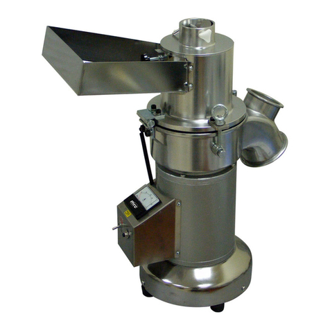
Rotor Beater Mill CM-100M3 is an advanced and efficient rotor beater mill from MRC, which
is suitable for soft, brittle sample materials grinding
CM-100M3 adopts a 3.7KW frequency control motor and frequency converter. It enables
continuous adjustment of speed from 3000~10000rpm, so as to meet different grinding
requirements for different properties samples.
2.1 General Instructions
As a user, be sure that you are authorized to use CM-100M3 and fully understand
technical documents before using
Before operation new user must be trained by skilled personnel or operate strictly
according to this instruction
. Read and fully understand the safety instructions before using
Please pay attention that improper handling may cause personal injury and damage to the
instrument. Please use it correctly
Please ensure that unqualified personnel do not operate the equipment
2.2 Warning
Please pay attention to the content of ‘Note’ in this manual to ensure your personal safety
and avoid damaging equipment.
Repair 2.3
This manual does not include any repair information. For your safety, please contact
MRC company’s authorized agents or MRC technical service center for repair
2.4 Safety Instructions
➢Please use it normally
MRC shall not be liable for any personal injury or damage to the equipment due to failure to
comply with the safety instructions
No changes can be made to the instrument, and use the accessories and fittings approved
by MRC. Otherwise, any of our warranty commitments will no longer be valid.
➢Packaging
Please keep the packing materials during the warranty. Otherwise, we shall not be able to
guarantee your rights in case of a packing complaint.

4
➢Transport
To avoid damage to electronic and mechanical parts of the instrument, the machine may not
be knocked, shaken or thrown during transport.
➢Temperature Change
If CM-100M3 is subjected to sharp temperature change (such as in air transport), the
formation of condensate should be prevented to avoid damage to electronic and mechanical
components.
➢Packing List
Upon receipt of the goods, if you find any shortage or damage to the equipment, please
inform the transport company or contact MRC within 24 hours. Delayed complaints may
not be accepted.
➢Installation Requirements
If the environment temperature is too high, too low or with high humidity, it may cause
damage to the electronic or mechanical parts of the instrument, and the performance will be
unknown.
➢Power Connection
Before connecting the power supply, please pay attention to the value on the nameplate of
the instrument so as not to damage the electronic or mechanical parts of the instrument.
3.0 Transportation and Installation
Packing 3.1
The packing is suitable for transportation and meets the CM-100M3 packing requirements.
Note:
Please retain the original packing during the warranty. In case the equipment is faulty, you need
to have it shipped back intact to avoid any damage during transit.
3.2 Transportation
During transportation, please do not throw, knock or oscillate, so as not to damage the
electronic and mechanical parts of the instrument.
Note:
If the temperature changes greatly (e.g., air transport), condensation water should be
prevented to avoid damaging the electronic components.
Storage 3.3
Please ensure that CM-100M3 is kept dry during storage
3.4 Supply List
CM-100M3 main machine:1set
Base frame:1 set
Collecting bucket:1 pc

5
⚫Manual:1 pc
After the goods are received, please check the delivery against the order or additional order
for completeness; if the delivery is incorrect or damaged in transit, please contact MRC
within 24 hours, after which time we will not accept the complaints
➢The clamping parts (door locks and contact parts with the chamber, sieves and plungers,
feed hopper, etc.) and grinding sets (e.g. rotary knives, bottom sieves, cutting prongs,
collection buckets, etc.) may have slight scratches, which are the result of factory testing
and are normal operation.
3.5 Ambient Temperature
From 5℃ to 40℃
Note:
When the ambient temperature is above or under the scope, the electronic and mechanical
components may be damaged, and performance changed to an unknown extent.
3.6 Air Humidity
At higher air humidity conditions, the electronic and mechanical components may be damaged,
and performance changed to an unknown extent.
3.7 Power Connection
The voltage and frequency of the power supply have been marked on the nameplate
Please keep the instrument working at the voltage indicated on the nameplate
please use the supplied CM-100M3 power cord
4.0 Technical Specifications
Introduction of Function 4.1
The CM-100M3 is able to handle large batches of material. After grinding, open the grinding
chamber door then the rotary knife and bottom sieve can be removed for easy cleaning by the
operator.
The CM-100M3 is suitable for continuous grinding of the same material and can be used for
periodic grinding.
Features:
⚫High-efficiency grinding;
⚫Suitable for batches and continuous sample grinding;
⚫The unique shape of the grinding tool and the perfect combination with the frequency-
controlled drive allows for fast, efficient grinding;
⚫Not suitable for wet grinding and hydrated samples;
⚫The rotor and grinding sets can be removed for instrument cleaning;
⚫The speed can be adjusted from 3000~10000 rpm continuously;
⚫The output sample fineness can be controlled by the aperture of the bottom sieve;
⚫Plug-type rotor and collecting device are easy to clean;

6
Fig 4.1.3.1
Fig 4.1.3.2
⚫360°and 180° two types of ring sieves are available. For soft, medium-hard and brittle
samples, the 180° ring sieve is chosen to achieve higher impact forces.
4.2 Electrical Parameters
Rated voltage:380V, 50/60Hz
Rated power:3.7KW
Motor speed:3000~10000rpm, adjustable continuously
Feed Size 4.3
CM-100M3≤25mm
4.4 Collecting Bucket
The max volume of collecting bucket is up to 5 L.
4.5 Instrument Size
⚫Grinding chamber(with motor):500x570x270 mm
⚫Base frame:630x705x885 mm
⚫5L collecting bucket: 210(diameter) x 200(height) mm
4.6 Weight
Net Weight: approx. 138kgs
4.7Floor Space
1m x 1m

7
5.0 Instrument Operation
5.1 Instrument Units(Fig 5.1.1~Fig 5.1.3)
(Accessories of rotor beater CM-100M3 grinding set(Fig 5.1.2
(CM-100M3-1) (CM-100M3-2) (CM-100M3-3)
(CM-100M3-4) (CM-100M3-5) CV
Fig 5.1.2
Fig.5.1.1

8
.
E
Fig 5.1.3
5.2 Units Function List
5.3 Open/Close Grinding Chamber Door (Fig 5.3.1)
Please open the door only after CM-100M3 stops working
Please grab handle B and turn it anticlockwise, then the door of grinding chamber is
unlocked and can be opened
Close and lock the grinding chamber door in reverse order
Part
Name
Function
A
Hopper
Feeds samples
B
Handle wheel
Open/close the lid
C
Collecting bucket
Receiving sample
D
Control panel
Parameter settings
CM-100M
3-1
Grinding chamber door,
feed hopper and handle for
rotor beater type
Feeds samples, seals up the grinding chamber
CM-100M
3-2
Accessories for rotor beater
grinding set
Reduce samples and installed on the door of
grinding chamber
CM-100M
3-3
The rotor of rotor beater type
Reduce samples
CM-100M
3-4
360°ring sieve
Grind samples, installed in the grinding chamber
CM-100M
3-5
180°ring sieve
Grinds samples, installed in the grinding chamber
CV
Cover of hopper
Seal up the feed port
E
Power switch
Power supply for the mill

9
B
CR200-1
CR200-4
CR200-3
Fig 5.3.1
Note:
➢The grinding chamber door can be closed only when the grinding chamber contact surface
without any samples or other remnants to prevent instrument components, chamber door
and seal rings from being damaged.
➢Please don’t open the chamber door when the motor is running. It’s dangerous to personal
safety.
➢Please take safety measures before grinding poisonous and unhealthy substances.
(Install/Disassemble the Rotor Beater Grinding Set Accessories(Fig 5.4.1~5.4.65.4
Step 1:Install CM-100M3-1
Install CM-100M3-1(door, hopper & grinding accessories)on the hinge of the grinding chamber
Step 2:Install the parts CM-100M3-4 /CM-100M3-5
Please align slot U(3 places total) in CM-100M3-4 with dowel G(3 places total), push CM-100M3-4
to the innermost position with both hands. The 2 location holes V should be inserted into the dowels
H when they are correctly positioned. Refer to Fig 5.6.2~5.6.4
Step 3:Install the rotor CM-100M3-3
Insert the CM-100M3-3 into shaft K and press it into the innermost place. Fix the CM-100M3-3 to
the drive shaft K with a piece of outer hexagonal bolt T(M8×90), refer to Fig 5.6.5~5.6.6
Note
Disassembling the CM-100M3 accessories can refer to the above steps but in reverse order

10
U
U
T
H
V
G
V
U
T
CR200-3
W
C
Fig 5.4.1
Fig 5.4.3 Fig 5.4.4
Fig 5.4.5 Fig 5.4.6
5.5 Collecting Bucket Installation (Fig 5.5)
⚫Hang the collecting bucket C
⚫Locking clamp W
Fig 5.7

11
4
5.6 Control Panel(Fig 5.6)
Fig 5.6
5.7 Control Panel Function List
No
Name
Function
1
Control panel
Parameter setting and control of the
instrument
2
Digital display tube
Display the running speed
3
Speed setting key
Increase the speed
4
Control knob
Speed and screen operation setting
5
Start key
Start the instrument
6
Stop key
Stop the instrument
7
Menu icon
Access to the instrument setup menu
8
Door open symbol
The symbol appears when the door is
open and disappears when the door is
closed.
Feed Sample Materials 5.8
Start the CM-100M3 at first, then start feeding the sample material.
Note
➢Excess sample amount will lead to instrument and components damages.
➢The maximum feed size must not exceed the specified feeding size, otherwise it will lead
to instrument breakdown and cause components damages.
➢Fill the sample material slowly and continuously into the feed hopper while the device is
running.

12
➢Breathing in the dust is hazardous to health!
Pay attention to the dust from the grinding substance. Any released dust may cause danger
to your health please take some protection measures and use an exhaust device.
➢Explosion hazard!
Please check the material properties before grinding to avoid the danger of an explosion.
5.9 Preparation Before Grinding
⚫Cut off the electric power
⚫Insert relative grinding accessories.
⚫Close and lock the grinding chamber well
⚫Fasten the collecting bucket
5.10 Start the Instrument
⚫Install all accessories well.
⚫Turn on the machine
⚫Set the needed speed by turning the control knob. Press the knob when the cursor
indicates the speed, the speed display changes color, turn the knob to set the speed,
press the knob to confirm when the setting is complete.
⚫Press “START”key to start the instrument.
⚫Slowly and uniformly feed the sample into the hopper till all samples are fed.
⚫Wait for the grinding to finish.
Note:
➢Wear protective gloves to avoid injury to your hands when handling the material;
➢Only use the feed shovel when pushing and pressing the material. Use of other auxiliary
parts may result in damage to the instrument components;
➢Do not feed multi-shaped materials as they may bounce back and cause you injury.
5.11 Stop the Instrument
Press“STOP ” key to stop the instrument.
Using the Cyclone 5.12
,CM-100M3 can connect with cyclone and vacuum to collect some light samples
eg: plastic bags, paper bags and packing material for milk products

13
10
8
9
6
7
5.13 Install the Cyclone
5.13.1 Units Introduction of the Cyclone
(Fig 5.13.1)
1. Cover of cyclone
2. Hopper of cyclone
3. Cover of 5L collecting bucket
4. Lock
5.5L collecting bucket
Hopper bracket and handwheel
Support bar
Hopper connecting with CM-100M3 sample
outlet (incl 4 pcs of hexagon socket button
head screws (M4x8
Support block of cyclone(incl 4 pcs of
hexagon socket head screws M6x12,1 pc of
hexagon socket countersunk head screw
(( M6x20
Fig 5.13.1
5.13.2 Installation Notes Fig 5.13.2.1~5.13.2.2
⚫Fasten the support bar 7 to the support block 9 with one of hexagon socket head screw
M6x20
⚫Install the above part assembled by support block 9 and the support bar 7 on the
CM100M3 base seat and fasten them with 4 pcs of hexagon socket head screws M4x8.
⚫Install hopper bracket 6 on support bar 7.
⚫Fixing the hopper 8 onto the outlet ring 10 with 4 pcs of hexagonsockethead screwsM4x8,
refer to fig 5.13.2.1
⚫Insert the feed hopper 2 into the round hole of hopper 8, and put them on bracket 6.
Adjusted bracket 6 to the proper height and fasten it with a hand wheel.
⚫Install the bucket cover 3 to the hopper 2 (thread connection)
⚫Fix bucket 5 and cover 3 with hang locks.
⚫Put cyclone cover 1 into hopper 2 and press 1 down to ensure seal up well.
⚫Disassembling can refer to the above steps but in reverse order.
Note:
please insert the exhaust tube of the vacuum cleaner into the interface on cover 1 when
connecting a vacuum cleaner.
Fig 5.13.2.1
1
2
3
4
6
4
5
7
8
9
6
7
8
9

14
4
3
1
Vacuum cleaner
connection port
2
5
Fig 5.13.2.2
5.14 Install the Vibratory Feeder VF200
5.14.1 Remove Screws for Transportation (Fig 5.14.1)
In order to ensure that the internal mechanical moving parts of the instrument are not damaged
during transport, the instrument is shipped with 4 hexagonal screws installed at the bottom of
the instrument. After removing the main unit from the box, the 4 screws on the bottom must be
removed before use.
Note: The tool for removing the screws, a 5mm hexagonal spanner, is included in the packing
list; TS1 and TS2 are M6 x 12, M6 x 16 cylindrical head hexagonal screws respectively.
5.14.2 Installation Notes of VF200 (Fig 5.14.2.1-5.14.2.2)
Step 1: Insert W3 the post of the hopper threading section into the hole located at the rear with
a white shim and thread the post tight.
Step 2: Insert W2 the hopper bracket into W3 and fix it at a proper height by the star-shaped
handwheel.
Step 3: Insert W1 the hopper into W2 and fixed tight.
Note:
➢W5 the feeding channel and W4 the channel base had been installed properly before
shipping;
➢The distance between W1 and W5 can be adjusted by W2 according to the sample feeding
TS2
TS2
2
TS1
TS1
Fig 5.14.1

15
size.
Step 4: Install Vibratory feeder VF200 in the support plate and fasten by 2pcs. of M4x20mm
hexagon socket head cap screws separately in V1, V2 positions. (Fig. 5.14.2.2)
Step 5: Place the support plate along with VF200 on the main machine CM-100M3 grinding
chamber and fasten by 3pcs. of M6x16mm hexagon socket head cap screws in position V3
(Fig 5.14.2.3-5.14.2.4)
Note:
; Disassemble the instrument, accessories in reverse order
. CM-100M3 is available with both cyclone and Vibratory Feeder VF200
5.14.3 VF200 Control Panel (Fig 5.14.3)
Fig 5.14.2.2
V1
V2
V1
V2
1
8
3
2
7
6
5
4
Fig 5.14.3

16
5.14.4 VF200 Control Panel Function List
6.0 Routine
6.1 Clean
Stop CM-100M3
Cut off the power before cleaning
Open the grinding chamber door
The rotor and sieve can be taken out for cleaning
Use alcohol and water to clean the rotor and bottom sieve, wipe dry with a dry cloth after
cleaning
The wear condition of the grinding kit should be checked regularly and replaced if necessary
Note:
⚫Do not use running water or any solvent to clean the instrument. Otherwise it may cause
shock or damage to the surface of the instrument. It is recommended to use a damp cloth
to clean the instrument.
⚫If necessary, the relevant grinding accessories can be removed and clean the instrument
with a long rush and industrial vacuum cleaner.
6.2 Safety Switch and Safety Inspections
When the instrument is in operation, it is forbidden to open the grinding chamber door. In case
the safety switch is invalid, it may cause personal injury or equipment damage.
Please check the instrument’s grinding chamber safety switch every half year:
Open the grinding chamber door and take out all grinding kits
Press“START”key and the instrument cannot be activated
Close grinding chamber door and press “START”, the instrument is activated
Note
Please contact MRC and inform the relative distributor if the instrument can still run
No.
Name
Function
1
Time display
Scope:00~99mins
2
Speed display
Scope:00~50
3
Start key
Start the instrument
4
Stop key
Stop the instrument
5
Speed decrease key
Decrease feeding speed
6
Speed increase key
Increase feeding speed
7
Time decrease key
Decrease feeding time
8
Time increase key
Increase feeding time

17
when the grinding chamber door is opening.
Maintenance 6.3
In order to ensure the reliable operation of the CM-100M3, the following maintenance shall
be carried out daily after use
⚫The grinding kit, rotor and sieve should be wiped dry after cleaning and placed in a dry
and ventilated place. If the grinding kit has not been used for a long time, a layer of anti-
rust oil should be applied to it;
⚫The heavy metal-free grinding kit is made of special steel material, which is more likely to
rust. But this will not affect the normal use of the grinding kit;
⚫The rotor shaft may rust due to frequent contact with the sample. To avoid this, it should
be cleaned and wiped with a dry cloth each time after use. If the instrument is not in use
for a long time, it is recommended to apply a layer of anti-rust oil on the knife shaft.
6.4 Accessories
Please do not make any changes to the instrument accessories, and only use the accessories
!provided by MRC, otherwise the warranty will be invalid
6.5 Wear
Grinding sets are composed of rotor, bottom sieve which are consumables. Wear and
consumption are normal. The extent of the wear depends on the use frequency and the nature
of the sample.
The wear condition of the grinding kit should be checked regularly and replaced if necessary.
Grinding kits are not covered by the warranty.
6.6 Testing
⚫When grinding samples with high toughness, the feed size should be minimized as far as
possible;
⚫If the original sample size is large, two steps of grinding are recommended:
Firstly, use the sieve with a larger aperture to pre-pulverize;
Then use the required sieve aperture for secondary grinding.
Copyright 6.7
Only under MRC's direct authorization may this information be copied or distributed. In case
.of infringement, we reserve the right to pursue legal liability
6.8 Modification
Technical improvements will be made without prior notice.

18
Appendix Instrument trouble shooting list
No.
Fault
Phenomenon
Fault Reason
Solution
1
Power on but no
display
1. Check if the power supply
fault
Replace or test the power
supply
2. Check if the power supply
switch fault
Replace the power supply
switch
3. Check if the power supply
socket fault
Replace the power supply
socket
4. Check if the flat cable
disconnects or poor
contact
Reconnect the wiring
5. Check the display or main
control circuit board fault
Contact us after sales
2
Display activated
but parameters
can’t be adjusted,
press STAR key
the machine
doesn’t work
1. Door control switch fault
Replace door control switch
2. Main control circuit board
fault
Contact us after sales
3. Face plate damaged
Contact us after sales
3
Display activated,
parameters can
be adjusted, but
press STAR key
the machine
doesn’t work
1. Face plate damaged
Contact us after sales
2. Motor fault
Contact us after sales
3. Circuit board fault
Contact us after sales
4. Frequency changer fault
Contact us after sales
5. Switching power supply
fault
Contact us after sales
4
Machine halt
suddenly during
working
1. Machine overload
Cut off power then clean the
grinding chamber, 2 mins later
turn on the power
2. Circuit board fault
Contact us after sales
3. Frequency changer fault
Contact us after sales
4. Switching power supply
fault
Contact us after sales
5
The idle running
noise gets louder
1. Adapter shafts position
bearing fault
Contact us after sales
2. Motor fault
Contact us after sales
3. Rotor contacts with bottom
sieve
Replace a new bottom sieve or
reinstall it
7
Sample output
less when using
trapezoid holes
sieves
1. Bottom sieve installation
direction fault
Adjust the direction of the
bottom sieve trapezoid holes
arrow to clockwise
8
Rotor can’t be
removed
1. The rotor or adapter shaft
has contamination
Use a scraper tool to remove
the contamination and clean
9
Rotor beat with
grinding chamber
1. Top axis position changing
Adjust top threads to move the
top axis position
1. Rotor installed fault
Reinstall the rotor
10
Grinding
chamber door
leak
1. Grinding chamber door not
closed properly
Clean and close the door
2. Seal ring aged or worn
Replace a new seal ring
11
Feeding hopper
1. Seal ring aged or worn
Replace a new seal ring

19
leak
2. The hopper didn’t install
properly
Reinstall the hopper
12
Discharge ring
leak
1. Seal ring aged or worn
Replace a new seal ring
2. The discharge ring didn’t
install properly
Reinstall the discharge ring
Table of contents
Other MRC Laboratory Equipment manuals
Popular Laboratory Equipment manuals by other brands

Millipore
Millipore Millicell ERS-2 user guide

Knauer
Knauer Azura Assistant ASM 2.1L user manual

Grant-bio
Grant-bio PHMP operating instructions

LW Scientific
LW Scientific MX5 Centrifuge instruction manual

Thermo Scientific
Thermo Scientific Varioskan user manual

Binder
Binder APT.line MK E2.1 Series operating manual