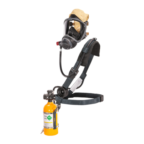
MSA PremAire Cadet 15M Manual

The warranties made by MSA with
respect to the product are voided if the
product is not installed, used, and ser-
viced in accordance with the instruc-
tions in this manual. Please protect
yourself and your employees by follow-
ing the instructions. Please read and
observe the WARNINGS and CAU-
TIONS inside. For any additional infor-
mation relative to use or repair, write or
call 1-800-MSA-2222 during regular
working hours.
TAL 4011 (L) Rev. 3 © MSA 2004 Prnt. Spec. 10000005389(A) Mat. 817081
Doc. 817081
This manual, including Warnings and
Cautions inside, must be read and fol-
lowed carefully by all persons who will
use or maintain the product, including
those who have any responsibility
involving its selection, application, ser-
vice or repair. This product will per-
form as designed only if used and
maintained according to the instruc-
tions. Otherwise, it could fail to per-
form as designed, and persons who
rely on this product could sustain seri-
ous personal injury or death.
!WARNING
PremAire
®
CADET 15M LEVEL II MAINTENANCE PROCEDURES

INTRODUCTION
This manual in intended for use with Department of
the Navy SAR/SCBA respirators only. Do not use the
procedures in this manual for maintaining self-con-
tained breathing apparatus (SCBA) regulators. Airline
regulators are designed for pressures up to 80psig.
Their use with an air source in excess of 80psig may
result in airline regulator rupture, causing serious per-
sonal injury or death.
Do not attempt repairs beyond those specified in this
manual. Only trained or certified personnel, authorized
by MSA, are permitted to maintain and repair this
apparatus. Breathing apparatus must not be repaired
beyond manufacturer's recommendations. OSHA 29
CFR Part 1910.134, Par. (f) (4) clearly defines these
requirements.
GENERAL NOTES
The General Notes which follow may be applied to all
applicable procedures.
NOTE 1: The maintenance procedures authorized in this
manual are classified Level II Maintenance. Level II is lim-
ited maintenance. It is intended for those trained and cer-
tified in using MSA Portable Regulator Testers.
NOTE 2: All O-rings and gaskets which are removed must
be replaced with new ones.
NOTE 3: Lubricate all O-rings with a very thin film of
Christo-Lube** (P/N 809059) before they are installed.
Christo-Lube lubricant is compatible with brass and alu-
minum.
NOTE 4: When installing O-rings over threads, use trans-
parent tape, a thin piece of paper, or other thread protec-
tor to avoid damage to the O-ring.
NOTE 5: Pipe-sealing tape is used on fittings with tapered
threads. Wrap 1 to 1-1/2 turns of tape in a clockwise
direction (looking into the threaded end of the fitting).
Start at the second thread. Do not put tape on the first
thread. Pieces of tape can break off and reduce air flow.
Apply a thin film of Christo-Lube lubricant to the outer
surface of the tape before threading the part into another
component.
Do not use Flourolube* lubricant (P/N 27912). It is not
compatible with aluminum. Failure to follow this warn-
ing can result in serious personal injury or death.
Refer to the appropriate Illustrated Parts List for the appa-
ratus being repaired.
Do not disconnect if pressurized. Always be sure to
release all pressure from the system. Removing the
coupling nut with the regulator pressurized can result
in serious personal injury, death, or damage to equip-
ment.
Leak test after each repair (see Level I).
* Fluorolube is a registered trademark of Hooker Chemical and
Plastics Company.
** Christo-Lube is a registered trademark of Lubrication Technologies.
2
TAL 4011 (L) Rev. 3 - 817081
TABLE OF CONTENTS
Introduction .........................................................................2
Mask Mounted (Second Stage) Regulator Repair ..............3
Mask Mounted Regulator Static Pressure Test ..................7
Cylinder Valve Repair ..........................................................8
High Pressure Regulator ...................................................11
Low Pressure Alarm ..........................................................11
Intermediate Pressure Hose..............................................11
High Pressure Hoses.........................................................12
!
!
!
!
!

MASK MOUNTED REGULATOR REPAIR
MASK MOUNTED (SECOND STAGE) REGULATOR
REPAIR
All repair procedures assume that the regulator is disas-
sembled from the apparatus and facepiece. To do this:
• Be sure the cylinder valve is completely closed.
• Disconnect the regulator from the facepiece.
• Be sure nothing is blocking the regulator outlet. Allow
any trapped pressure to bleed from the apparatus.
• If desired, disconnect the intermediate pressure hose
from the first stage regulator.
Note: Use only specified thread sealants in their specified
locations. Use of sealants other than the ones specified
may damage MMR (Second Stage) components.
Removing the Shut-Off Cap, Spring, and Stop Spring
1. Remove the setscrew
from the regulator
housing.
2. Unthread the shut-off cap and remove the button and
spring.
3. Pull the stop spring out
of the groove at the
bottom of the shut-off
hub.
4. Remove any RTV Adhesive from the shut-off hub.
5. Fit the large spanner
wrench on the socket
driver. Unthread the
shut-off hub from the
regulator housing.
6. Using the small span-
ner wrench, unthread
the adjusting screw
from the shut-off hub.
7. Remove the diaphragm spring.
8. Clean sealant residue from parts.
Note: Use extreme care when removing the diaphragm.
Do not bend, twist, or distort the lever assembly. Do not
touch the exposed lever assembly after removing the
diaphragm.
9. Lift the diaphragm and
spacer ring from the
housing.
Note: If the regulator diaphragm is torn or has any visible
damage, it must be replaced.
Installing a New Diaphragm or Spring
1. Lay the diaphragm on
a flat, clean surface
and place the spacer
ring into the diaphragm's
outer rim. The flange
side must be "up."
2. Install this assembly
into the regulator hous-
ing by pushing gently
on the spacer ring.
3TAL 4011 (L) Rev. 3 - 817081

MASK MOUNTED REGULATOR REPAIR
Push gently on the diaphragm or damage to the lever
assembly could affect regulator operation.
3. Thread the shut-off hub into the regulator housing.
4. Fit the large spanner
wrench on the inch-
pound torque wrench
and torque to 10-
15in.lbs.
5. Insert the small diaphragm spring through the center
hole in the shut-off hub so it rests over the center nip-
ple of the diaphragm. This spring has to fit around the
rib on top of the diaphragm.
6. Thread the adjusting screw into the shut-off hub.
7. Adjust the static pressure. (see Static Pressure)
8. Perform the Static Pressure Test and the Flow Test to
check the final assembly.
Removing the Valve Core
Note: Internal parts of the valve core are not replaceable.
The valve core must be replaced as a complete unit.
However, the screen may be removed and replaced, as
can the O-ring at the swivel block end.
1. Remove the end cap, diaphragm, and spring. (see
Removing the Shut-off Cap, Spring and Stop Spring)
2. Disconnect the unpressurized mask mounted regulator
from the facepiece.
3. Using a 1" open-end
wrench, unthread the
knob securing the hose
to the regulator.
4. Pull the swivel shaft
gently out of the regu-
lator body.
5. Using the O-ring
removal tool, pull the
inlet screen from the
regulator. Inspect the
screen for corrosion,
dirt, or debris. Replace
the screen if necessary.
6. Visually inspect the two O-rings on the inlet swivel
shaft. Replace the O-rings if they are worn or dam-
aged.
Do not press on the lever assembly or unthread the
valve and lever assembly from the valve body. This
could affect operation.
7. To remove the valve
core from the regulator
body, hold the body as
shown. Gently push the
end of the valve core
with your thumbs to
unseat the O-ring and
valve core.
8. Cup one hand under
the body and support
the valve core as it
slides out of the body.
9. Remove and discard the external sleeve O-ring.
4
TAL 4011 (L) Rev. 3 - 817081
!
!

MASK MOUNTED REGULATOR REPAIR
Removing the Inlet Screen, Internal Sleeve, O-Ring,
Power Stage Spool, and Power Stage Diaphragm
Do not press on the lever assembly. Do not unthread
the base and lever assembly or the divider skirt from
the valve core. This could damage the bottom lever
pad and affect operation.
1. Place a 1" wrench on the hex flats to secure base and
lever assembly.
2. Turn the sleeve
counter-clockwise to
unthread it from
base/lever.
3. Remove and discard
the internal sleeve O-
ring.
4. Inspect the inlet screen and replace it if it is damaged.
5. Remove the power
stage diaphragm and
discard it. Use the plas-
tic stick if necessary to
remove the diaphragm.
Installing the Inlet Screen, Sleeve O-Ring, Power
Stage Spool, and Power Stage Diaphragm
1. Clean any debris from inside the valve core before
reassembly.
2. Place a new diaphragm
into the valve and lever
assembly. Ensure the
flat side of the
diaphragm faces up
and that the diaphragm
rib nests into the
matching groove inside
the assembly. Use the
plastic stick if neces-
sary to be sure the
diaphragm is seated.
3. Place the power stage
spool into the valve
assembly with the ring
of holes against the
power stage
diaphragm.
4. Center the screen on the power stage spool. Ensure
the open end of the screen faces up.
5. Place a thin film of
Christo-Lube lubricant
on a new O-ring and
install it in the groove
in the sleeve.
6. Place one drop of
Loctite* #222 adhesive
on the large threads of
the sleeve.
Note: Ensure the sleeve O-ring stays in its groove on the
end of the sleeve during reassembly.
Do not grasp the lever base during the next step. Hold
the valve body hex, not the base and lever assembly.
5TAL 4011 (L) Rev. 3 - 817081
!
!

MASK MOUNTED REGULATOR REPAIR
7. Place a 1" wrench on the hex flats of the base and
lever assembly. Thread the sleeve into the valve and
lever assembly clockwise hand-tight.
Installing the Valve Core
1. Place transparent tape over the exposed threads of
the valve core to protect the new external O-ring.
2. Place a thin film of Christo-Lube lubricant on the new
external sleeve O-ring.
3. Roll the O-ring in place
in the groove closest to
the valve body.
4. Remove all tape.
5. Line up the wide rec-
tangular slot in the
valve body hex with the
lug inside the regulator
housing.
Do not push on the top lever while installing the valve
core. This could damage the pad seal and affect oper-
ation. Place your fingertips on the two shoulders on
either side of the lever arms.
6. With the slot and lug
lined up, press the
valve core gently into
the housing.
Resistance will develop
as the O-ring is forced
into its seat.
Do not turn the valve and lever assembly relative to
the valve core. This could damage the pad seal and
affect operation.
7. Place one drop of adhesive on the exposed valve core
threads. Do not permit thread sealant to contact the
regulator housing.
8. Re-install the knob, swivel block, and hose on the reg-
ulator housing and tighten using a 1" wrench. (see
Removing the Valve Core)
9. Re-install diaphragm, spring, shut-off hub, and the
adjusting screw in the regulator housing. (see
Adjusting the Static Pressure Setting)
Do not press on the lever assembly or unthread the
valve and lever assembly from the valve body. This
could affect operation.
10. Perform the Static Pressure Test and the Flow Test to
check the final assembly.
6
TAL 4011 (L) Rev. 3 - 817081
!
!
!
* Loctite is a registered trademark of Loctite Corporation

SECOND STAGE REGULATOR STATIC PRESSURE TEST
SECOND STAGE REGULATOR STATIC PRESSURE
TEST
Adjusting the Static Pressure Setting
1. Remove the shut-off cap, the shut-off push button,
the shut-off spring (P/N 492238), and the stop spring
from the regulator housing. (see Removing the Shut-
off Cap, Spring, and Stop Spring)
2. Using the small spanner wrench, unthread the thrust
ring from the shut-off hub.
Note: Be sure that the adjusting screw remains in the
shut-off hub.
3. Attach the regulator to the tester suitable for the MMR
Airline Apparatus (PosiChek3 Tester).
Note: MSA recommends using the biosystems PosiChek3
Computerized Performance Tester to conduct flow tests.
4. Connect and test the Premaire CADET15M by follow-
ing the user's instructions for Airline apparatus sup-
plied with the PosiChek3 tester.
5. Attach the Airline Adaptor and pressurize the system.
6. Adjust the static pressure by turning the adjusting
screw with the small spanner wrench. The static pres-
sure should be 1.1 to 1.3 inches water column.
7. Using a toothpick,
place one drop of RTV
Adhesive in the joint
between the adjusting
screw and shut-off hub.
8. Clean any excess RTV Adhesive from the threads of
the thrust ring.
9. Place one drop of RTV Adhesive on the threads of the
shut-off hub above the adjusting screw.
10. Thread the thrust ring into the shut-off hub until it is
flush with the top surface of the base or until it con-
tacts the adhesive screw. Do not over-tighten.
11. Using a toothpick, place a small bead of RTV
Adhesive (P/N 603556) in the groove at the bottom of
the shut-off hub.
12. Place the stop spring (P/N 800685) over the shut-off
hub. Push down on the spring until the bottom coil
snaps into place.
13. Replace the shut-off button and the spring in the shut-
off cap.
14. Thread the shut-off cap on the regulator housing until
the shut-off cap touches the shut-off hub.
15. Further tighten the cap clockwise until the next index-
ing mark lines up with the setscrew hole in the regula-
tor housing.
Note: The cap slot locations are the six marks above the
threads on the cap.
16. Carefully thread the setscrew in until the top of the
setscrew is snug in the regulator housing.
17. Re-check the static pressure setting. The final setting
must be 1.2 to 1.4 inches water column.
18. Flow test to check the final assembly.
Note: When flow testing Premaire CADET 15M System,
refer to the test procedures in the instructions for Airline
supplied with the tester to be used.
7TAL 4011 (L) Rev. 3 - 817081

CYLINDER VALVE REPAIR
CYLINDER VALVE DISASSEMBLY AND REPAIR
Before repairing the cylinder valve, all air must be bled
from the cylinder. Open the cylinder valve handwheel
1/2 turn and leave it open until all air has been
exhausted. Wear hearing protection if this is done in
an enclosed area to avoid possible hearing damage.
Do not attempt to repair the valve if pressure is shown
on the cylinder pressure gauge. If pressure cannot be
relieved by opening the cylinder valve handwheel, the
cylinder must be repaired. Failure to follow these
warnings can result in serious personal injury or death.
Removing the Handwheel
1. Using the spanner
wrench, remove the
locknut and spring.
2. Remove the handwheel from the top of the valve
stem.
3. Place a 7/8" socket (deep-well) on the packing gland
from the valve body. Pull the stem out of packing
gland.
4. Remove the O-ring and
valve stem washer from
the packing gland.
Note: The O-ring removal
tool can be used to remove
the O-ring from the packing
gland.
5. Replace the handwheel on the valve stem.
6. Place the valve stem
back in the valve body.
Turn the stem until the
slot drops onto the
insert.
7. Turn the handwheel counter-clockwise until the insert
can be removed.
Note: If the insert shows signs of wear or damage it must
be replaced.
Installing the Insert
1. Using the valve stem,
install the insert in the
valve body. Thread the
stem clockwise until
the insert is finger-tight.
2. Place a thin film of Christo-Lube lubricant on a new
O-ring.
3. Place the O-ring on the packing gland.
4. Place a new washer into the packing gland. Press the
washer down to its seal.
5. Insert the stem into the valve body. Turn the stem until
the slot drops on the insert. Thread the packing gland
into the cylinder valve until it is finger-tight.
6. Turn the valve stem counter-clockwise until the stem
stops. Be sure the gland does not turn.
7. Using the inch-pound torque wrench with a 7/8" sock-
et (deep-well), tighten the packing gland to 85-105
in.lbs.
8. The valve stem square must fit into the square hole in
the handwheel. Place the handwheel on the stem and
check the valve for proper motion. The handwheel
should move freely.
9. Replace the spring. Ensure the valve is fully open to
allow the locknut to be installed more easily.
10. Put one drop of Loctite #222 on the stem threads.
11. Using the locknut spanner wrench, press the locknut
against the spring and tighten clockwise until it is flush
with the top of the handwheel.
12. Open and close the valve completely several times to
seat the stem, insert, and the valve stem gasket.
13. Leak test the valve (see Level I).
8
TAL 4011 (L) Rev. 3 - 817081
!

CYLINDER VALVE REPAIR
Removing the Burst Disc
Before repairing the cylinder valve, all air must be bled
from the cylinder. Open the cylinder valve handwheel
1/2 turn and leave it open until all air has been exhaust-
ed. Wear hearing protection if this is done in an
enclosed area to avoid possible hearing damage. Do
not attempt to repair the
valve if pressure is
shown on the cylinder
pressure gauge. If pres-
sure cannot be relieved
by opening the cylinder
valve handwheel, the
cylinder must be repaired
by MSA Level III repair-
person. Failure to follow
these warnings can
result in serious personal
injury or death.
1. Place a 3/4" socket on the safety plug hex flats and
turn the plug counter-clockwise to remove the safety
plug.
2. Using a screwdriver, punch a hole in the burst disc.
3. Pull the burst disc out of the cylinder valve body.
4. Discard the disc.
5. Using the O-ring removal tool, lift the gasket out of the
cylinder valve body. Be careful not to scratch the sur-
face of the cylinder valve body.
Installing a New Burst Disc
1. Insert a new gasket into the cylinder valve body.
2. Place a thin film of Snoop on the new burst disc.
3. Place the new burst
disc on top of the gas-
ket. Ensure the gasket
and disc lay flat.
Be sure the gasket, then the burst disc, are installed in
the order described. Failure to install properly may
cause burst disc malfunction and can result in serious
personal injury or death.
Do not re-use the burst disc or the copper gasket.
4. Thread the safety plug into the cylinder body.
5. Using a torque wrench and socket, tighten the plug to
the torque of 26-30 ft.lbs.
6. Leak test the assembly (see Level I).
This completes the burst disc repair procedure.
Replacing the Cylinder Inlet Body
1. To remove the cylinder inlet body from the cylinder:
Before repairing the cylinder valve, all air must be bled
from the cylinder. Open the cylinder valve handwheel
1/2 turn and leave it open until all air has been
exhausted. Wear hearing protection if this is done in
an enclosed area to avoid possible hearing damage.
Do not attempt to repair
the valve if pressure is
shown on the cylinder
pressure gauge. If pres-
sure cannot be relieved
by opening the cylinder
valve handwheel, the
cylinder must be
repaired. Failure to follow
these warnings can
result in serious personal
injury or death.
a. Secure the cylinder in a suitable fixture.
b. Place a 1 1/8" crowsfoot wrench on the flats on the
end of the cylinder valve. Turn the valve counter-
clockwise until the cylinder valve is completely out
of the cylinder.
c. Roll the O-ring over the threads.
d. If the cylinder valve inlet is damaged it must be
removed.
2. Use a high intensity light to inspect the inside of the
cylinder for contamination. Be sure the cylinder interior
is completely dry.
Do not use the cylinder if it has an odor, is contami-
nated internally, or has any visible signs of damage. If
the cylinder appears damaged return it to a Certified
Level III MSA Air Mask Service Center for repair.
3. Clean the O-ring sealing surface on the cylinder with a
clean, dry, lint-free cloth. Be sure the cylinder sealing
surface is undamaged and free from contaminants,
such as dirt or tape residue.
4. Inspect the cylinder neck area. Do not use the cylinder
if it has scratches, cuts, or grooves which may prevent
an air-tight seal.
5. Install a new O-ring on the cylinder valve following the
steps below:
Apply Christo-Lube lubricant to the O-ring and the O-
ring groove just before installing the cylinder valve. Do
not store these parts after lubricating them. Christo-
Lube lubricant may collect dirt and/or contaminants.
9TAL 4011 (L) Rev. 3 - 817081
!
!
!
!
!
!
Burst Disk

CYLINDER VALVE REPAIR
a. Place a thin film of Christo-Lube lubricant on the
new O-ring.
b. Place two small diameter drops of Christo-Lube into
the O-ring groove at locations 180 degrees apart.
c. Place a plastic thread protector or thin piece of
paper over the threads, then roll the O-ring to the
bottom (male thread) end of the valve body.
d. Remove the thread protector.
6. Carefully insert the cylinder inlet into the cylinder neck
so that the sealing surface of the cylinder is not dam-
aged.
7. Use the foot-pound torque wrench with a 1 1/8"
crowsfoot wrench to tighten the cylinder inlet to 70-75
ft.lbs.
8. Leak test the assembly (see Level I).
This completes the cylinder replacement procedure.
Before repairing the cylinder valve, all air must be bled
from the cylinder. Open the cylinder valve handwheel
1/2 turn and leave it open until all air has been
exhausted. Wear hearing protection if this is done in
an enclosed area to avoid possible hearing damage.
Do not attempt to repair the valve if pressure is shown
on the cylinder pressure gauge. If pressure cannot be
relieved by opening the cylinder valve handwheel, the
cylinder must be repaired. Failure to follow these
warnings can result in serious personal injury or
death.
Removing the Cylinder Pressure Gauge
1. Remove or loosen the cylinder band.
2. Position the cylinder valve so that the gauge is
upside-down to prevent dirt and debris from falling
into the bore of the valve assembly.
3. Place a 7/16" open-
end wrench on the
gauge flats. Turn the
gauge counter-clock-
wise to loosen.
4. Clean out the threads in the cylinder valve body to be
sure no tape residue remains.
Installing a New Pressure Gauge
1. Place pipe-sealing tape on the gauge threads. (see
General Note 5)
2. Place a 7/16" open-end wrench on the gauge flats.
Turn the gauge clockwise to tighten.
3. Position the gauge so that it can be read in the "as-
worn" position. Do not over-tighten.
4. Replace or tighten cylinder band.
5. Leak test all connections.
This completes the cylinder pressure gauge replacement
procedures.
10
TAL 4011 (L) Rev. 3 - 817081
!

HIGH PRESSURE REGULATOR
HIGH PRESSURE REGULATOR DISASSEMBLY AND
REPAIR
Do not over-tighten parts or you may damage the part
or the fitting threads.
Note: All repair procedures assume that the regulator is
disconnected from the apparatus cylinder.
• Be sure the cylinder valve is completely closed.
• Be sure that nothing blocks the regulator outlet.
• Relieve pressure in the system.
Do not disconnect the first coupling nut when pres-
sure is shown on the harness gauge. Always be sure
that all pressure is released from the regulator.
Removing the coupling nut with the regulator pressur-
ized can result in serious personal injury or death.
• Unthread the First Stage Regulator coupling nut from
the cylinder valve.
HIGH PRESSURE REGULATOR INLET O-RING
1. Insert the O-ring removal tool under the O-ring
(P/N 633553) and remove it. Be careful not to
scratch the regulator inlet O-ring groove.
2. Apply a light film of Christo-Lube lubriant to the new
O-ring.
3. Roll the new O-ring over the end of the insert and seat
it into the O-ring groove. If the O-ring is not seated, air
may leak.
LOW PRESSURE ALARM
Removing the Low Pressure Alarm (Whistle)
1. Using a 11/16" wrench, turn the whistle counter-clock-
wise.
2. Unthread the alarm
from the High Pressure
Regulator.
Installing the Low Pressure Alarm (Whistle)
1. Insure that O-ring is seated and not damaged.
2. Apply a thin film of Christo-Lube lubricant to the O-ring.
3. Thread the alarm into
the High Pressure
Regulator clockwise by
hand. Tighten with an
11/16" crowsfoot
wrench and torque to
15±5 ft.lbs.
4. Refer to the User's Instructions to perform the Leak
and Function Tests.
Leak and Function Testing of Low Pressure Alarm
1. Ensure that Mask Mounted Regulator is attached to
the Pressure Regulator.
2. Pressurize the system.
3. Use leak test solution to test the connection of the
whistle at the regulator body.
4. Use the valve to slowly bleed off the pressure.
5. The whistle should sound as pressure goes to zero.
INTERMEDIATE PRESSURE HOSE
Removing the Intermediate Pressure Hose from the
High Pressure Regulator
1. Disconnect the intermediate hose from the High
Pressure Regulator.
2. Use a 9/16" open-end wrench, turn the 45 (degrees)
adapter counter-clockwise.
Installing the Intermediate Pressure Hose on the High
Pressure Regulator
1. Remove the old tape. Be careful not to damage the
metal seat area.
2. Install a new tape. (Refer to General Note 5)
3. Reconnect the intermediate hose if no further repair to
the regulator is required. Tighten with a 9/16" wrench.
11 TAL 4011 (L) Rev. 3 - 817081
!
!

HIGH PRESSURE REGULATOR
Removing the Airline Hose from the High Pressure
Regulator
1. Use a 9/16" wrench to unthread the hose from the
regulator body.
Installing the Airline Hose on the High Pressure
Regulator
1. Thread the airline hose into the regulator body.
2. Using a 5/8" wrench, tighten the airline hose.
Replacing the Check Valve Adapter on the Airline
Hose
1. Remove the check valve from the hose. Ensure the
washer is present.
2. Using a 11/16" open-end wrench on the hose and a
5/8" open-end wrench on the adapter, separate the
hose from the check valve adapter.
3. Hold the adapter with 5/8" open-end wrench and 5/8"
wrench on male disconnect.
4. Remove and replace the tape on both ends of check
valve.
5. Thread the hose on the new adapter. Using a 5/8" on
the adapter and a 11/16" wrench on the hose and
tighten.
6. Thread the male disconnect onto the check valve
adapter and tighten.
HIGH PRESSURE HOSE
All repair procedures assume that the cylinders are
depressurized.
Removing the High Pressure Hose from Cylinder Valve
Body
1. Using a 1/4" socket, remove the four (4) screwpins
from the cylinder valve.
2. Pull firmly on the high pressure hose to remove it from
the cylinder valve body.
3. Remove the old O-ring and back-up ring. Be careful
not to damage the O-ring seal area.
Removing the High Pressure Hose from Cylinder Inlet
1. Place a 9/16" wrench on the hex flats of the hose fit-
ting.
2. Unthread in a counter-clockwise direction to remove
the high pressure hose.
3. Using the O-ring removal tool, remove the tape from
the hose fitting. Be careful. Do not damage the O-ring
seal area.
Installing the High Pressure Hose on the Cylinder Inlet
1. Use tape to cover the hose fitting threads.
2. Install new tape on the high pressure hose fitting.
Lubricate the tape.
3. Hand-thread the hose fitting clockwise into the cylin-
der inlet outlet.
4. Tighten with a 9/16" crowsfoot wrench to a torque of
90 in.lbs.
Installing the High Pressure Hose on the Cylinder
Valve Body
1. Install a new back-up ring and a new O-ring on the
hose fitting.
2. Insert the high pressure hose into the cylinder valve.
3. Insert a new screw pin into each of the holes in the
cylinder valve body. Use a 1/4" socket to tighten pins.
This completes the high pressure hose replacement pro-
cedure.
12
TAL 4011 (L) Rev. 3 - 817081

Table of contents
Other MSA Respiratory Product manuals

MSA
MSA G1 Facepiece User manual
MSA
MSA G1 SCBA User manual

MSA
MSA OptimAir MM PAPR User manual

MSA
MSA FireHawk M7 Responder PAPR User manual

MSA
MSA G1 SCBA User manual

MSA
MSA OptimAir TL PAPR User manual

MSA
MSA 3S small User manual

MSA
MSA SSR 30/100 User manual

MSA
MSA advantage 1000 User manual

MSA
MSA 3S small User manual

MSA
MSA AirXpress One Fire User manual

MSA
MSA Phalanx Alpha Operation manual

MSA
MSA alpha Series User manual

MSA
MSA TransAire User manual

MSA
MSA 3S-R AirElite Full Face Mask User manual

MSA
MSA Ultra Elite P100 User manual

MSA
MSA FireHawk M7 User manual

MSA
MSA Advantage 900 User manual

MSA
MSA Advantage 3200 User manual

MSA
MSA FireHawk M7 I-HUD User manual