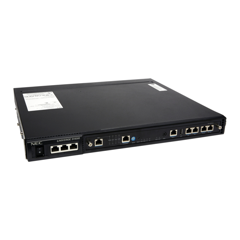
NEC IE-703102-MC-EM1 User manual

User’s Manual
Target device
V850E/MS1TM
IE-703102-MC-EM1,
IE-703102-MC-EM1-A
In-circuit Emulator Optional Board
1991©
Document No. U13876EJ1V0UM00 (1st edition)
Date Published December 1998 N CP(K)
Printed in Japan
1998

2
[MEMO]

3
V850E/MS1 is a trademark of NEC Corporation.
Windows is either a registered trademark or a trademark of Microsoft Corporation in the United States
and/or other countries.
PC/AT is a trademark of International Business Machines Corporation.
Ethernet is a trademark of Xerox Corporation.
UNIX is a registered trademark in the United States and other countries, licensed exclusively through
X/Open Company Limited.
The information in this document is subject to change without notice.
No part of this document may be copied or reproduced in any form or by any means without the prior written
consent of NEC Corporation. NEC Corporation assumes no responsibility for any errors which may appear in
this document.
NEC Corporation does not assume any liability for infringement of patents, copyrights or other intellectual
property rights of third parties by or arising from use of a device described herein or any other liability arising
from use of such device. No license, either express, implied or otherwise, is granted under any patents,
copyrights or other intellectual property rights of NEC Corporation or of others.
M7A 96.10

4
Regional Information
Some information contained in this document may vary from country to country. Before using any NEC
product in your application, pIease contact the NEC office in your country to obtain a list of authorized
representatives and distributors. They will verify:
•
Device availability
•
Ordering information
•
Product release schedule
•
Availability of related technical literature
•
Development environment specifications (for example, specifications for third-party tools and
components, host computers, power plugs, AC supply voltages, and so forth)
•
Network requirements
In addition, trademarks, registered trademarks, export restrictions, and other legal issues may also vary
from country to country.
NEC Electronics Inc. (U.S.)
Santa Clara, California
Tel: 408-588-6000
800-366-9782
Fax: 408-588-6130
800-729-9288
NEC Electronics (Germany) GmbH
Duesseldorf, Germany
Tel: 0211-65 03 02
Fax: 0211-65 03 490
NEC Electronics (UK) Ltd.
Milton Keynes, UK
Tel: 01908-691-133
Fax: 01908-670-290
NEC Electronics Italiana s.r.l.
Milano, Italy
Tel: 02-66 75 41
Fax: 02-66 75 42 99
NEC Electronics (Germany) GmbH
Benelux Office
Eindhoven, The Netherlands
Tel: 040-2445845
Fax: 040-2444580
NEC Electronics (France) S.A.
Velizy-Villacoublay, France
Tel: 01-30-67 58 00
Fax: 01-30-67 58 99
NEC Electronics (France) S.A.
Spain Office
Madrid, Spain
Tel: 01-504-2787
Fax: 01-504-2860
NEC Electronics (Germany) GmbH
Scandinavia Office
Taeby, Sweden
Tel: 08-63 80 820
Fax: 08-63 80 388
NEC Electronics Hong Kong Ltd.
Hong Kong
Tel: 2886-9318
Fax: 2886-9022/9044
NEC Electronics Hong Kong Ltd.
Seoul Branch
Seoul, Korea
Tel: 02-528-0303
Fax: 02-528-4411
NEC Electronics Singapore Pte. Ltd.
United Square, Singapore 1130
Tel: 65-253-8311
Fax: 65-250-3583
NEC Electronics Taiwan Ltd.
Taipei, Taiwan
Tel: 02-2719-2377
Fax: 02-2719-5951
NEC do Brasil S.A.
Electron Devices Division
Rodovia Presidente Dutra, Km 214
07210-902-Guarulhos-SP Brasil
Tel: 55-11-6465-6810
Fax: 55-11-6465-6829
J98. 11

5
INTRODUCTION
Readers This manual is intended for users who design and develop application systems
using the V850E/MS1TM.
Purpose The purpose of this manual is to describe the proper operation of the IE-703102-MC-
EM1 and IE-703102-MC-EM1-A, and their basic specifications.
Organization This manual is broadly divided into the following parts.
• Overview
• Name and function of components
• Cautions
How to Read This Manual It is assumed that the reader of this manual has general knowledge of electrical
engineering, logic circuits, and microcontrollers.
The IE-703102-MC-EM1 and IE-703102-MC-EM1-A are used connected to the
IE-703102-MC in-circuit emulator. This manual explains the basic setup
procedure and switch settings of the IE-703102-MC-EM1 and IE-703102-MC-
EM1-A. For the names and functions, and the connection of parts, refer to the
IE-703102-MC User’s Manual, which is a separate volume.
To understand the basic specifications and operation methods broadly
→Read this manual in the order listed in CONTENTS.
To know the operation methods and command functions of the IE-703102-MC, IE-
703102-MC-EM1, and IE-703102-MC-EM1-A
→Read the user’s manual of the debugger (separate volume) that is used.
Conventions Note: Footnote for item marked with Note in the text
Caution: Information requiring particular attention
Remark: Supplementary information
Numeral representations: Binary …×××× or ××××B
Decimal …××××
Hexadecimal …××××H
Prefixes representing the powers of 2 (address space, memory capacity):
K (kilo): 210 = 1024
M (mega): 220 = 10242
Terminology The meanings of terms used in this manual are listed below.
Target device Device that is emulated.
Target
system The system (user-built system) to be debugged. This includes the target
program and user-configured hardware.

6
Product Names Unless otherwise specified, the IE-703102-MC-EM1 is treated as the representative model
in this manual. When using the IE-703102-MC-EM1-A, read IE-703102-MC-EM1 as IE-
703102-MC-EM1-A. For functional differences between IE-703102-MC-EM1 and IE-
703102-MC-EM1-A, refer to CHAPTER 1 OVERVIEW.
Related Documents The related documents indicated in this publication may include preliminary versions.
However, preliminary versions are not marked as such.
{Documents related to V850E/MS1
Document Name Document Number
V850E/MS1 User’s Manual-Hardware U12688E
V850E/××× User’s Manual-Architecture U12197E
µ
PD703100-40, 703101-33, 703102-33 Data Sheet To be prepared
µ
PD703100-A40, 703101-A33, 703102-A33 Data Sheet To be prepared
µ
PD70F3102-33 Data Sheet U13844E
µ
PD70F3102-A33 Data Sheet U13845E
{Documents related to development tools (User’s Manual)
Product Name Document Number
IE-703102-MC (In-circuit emulator) U13875E
IE-703102-MC-EM1, IE-703102-MC-EM1-A (In-circuit emulator optional board) This manual
Operation UNIXTM based U12839E
Operation WindowsTM based U12827E
C language U12840E
CA850 (C Compiler package)
Assembly Language U10543E
ID850 (Integrated debugger) Operation Windows based U13716E
Basics U13430E
Technical U13431E
RX850 (Real-time OS)
Installation U13410E
Fundamental Under preparation
Technical U13772E
RX850 Pro (Real-time OS)
Installation U13774E
RD850 (Task debugger)Note U11158E
RD850 (Ver. 3.0) (Task debugger) U13737E
AZ850 (System performance analyzer) Operation U11181E
Note Supports ID850 (Ver. 1.31 only)

7
CONTENTS
CHAPTER 1 OVERVIEW.........................................................................................................................11
1.1 Hardware Configuration .............................................................................................................12
1.2 Features (When Connected to IE-703102-MC)..........................................................................13
1.3 Function Specifications (When Connected to IE-703102-MC)................................................14
1.4 System Configuration.................................................................................................................15
1.5 Contents in Carton......................................................................................................................16
1.6 Connection between IE-703102-MC and IE-703102-MC-EM1 ..................................................17
CHAPTER 2 NAME AND FUNCTION OF COMPONENTS.................................................................19
2.1 Component Name and Function of IE-703102-MC-EM1 ..........................................................19
2.2 Clock Settings..............................................................................................................................21
2.3 MODE Pin Setting........................................................................................................................22
2.3.1 MODE pin setting when emulator is used as stand-alone unit...................................................... 22
2.3.2 MODE pin setting when emulator is used connected to target system ......................................... 22
2.4 Power Supply Settings ...............................................................................................................23
2.4.1 JP2 setting when the emulator operates as a stand-alone unit and target system power is off.... 23
2.4.2 JP2 setting when power of the target system is on.......................................................................23
CHAPTER 3 FACTORY SETTINGS.........................................................................................................25
CHAPTER 4 CAUTIONS..........................................................................................................................27
4.1 VDD and HVDD of Target System..................................................................................................27
4.2 X1 Signal ......................................................................................................................................27
4.3 Pin Termination ...........................................................................................................................28
4.4 Internal RAM and ROM ...............................................................................................................29
4.5 Port 4 to 6, A, and B ....................................................................................................................30
4.6 Bus Interface Pin.........................................................................................................................31
4.7 Emulation Memory Operation Timing Difference.....................................................................33
APPENDIX A DIMENSIONS....................................................................................................................35
APPENDIX B EXAMPLE OF USE OF CONNECTOR FOR TARGET CONNECTION....................41
APPENDIX C CONNECTORS FOR TARGET CONNECTION.............................................................43
C.1 Use................................................................................................................................................43
C.2 Cautions on Handling Connectors............................................................................................45
APPENDIX D MOUNTING OF PLASTIC SPACER..............................................................................47
8
LIST OF FIGURES
Figure No. Title Page
1-1. System Configuration.......................................................................................................................................15
1-2. Contents in Carton............................................................................................................................................16
1-3. Connection between IE-703102-MC and IE-703102-MC-EM1.........................................................................17
2-1. IE-703102-MC-EM1..........................................................................................................................................19
2-2. Power Supply Settings (When the Emulator Operates as a Stand-Alone Unit and Target System Power is Off)
..........................................................................................................................................................................23
2-3. Power Supply Setting (When Power of the Target System is On)....................................................................23
4-1. Schematic Diagram of Power Supply Flow.......................................................................................................27
4-2. Diagram of X1 Signal Flow...............................................................................................................................28
4-3. Circuit Diagram of CKSEL Pin..........................................................................................................................28
4-4. Circuit Diagram of Port 4 to 6, A, and B ...........................................................................................................30
C-1. Mounting of NQPACK144SD............................................................................................................................43
C-2. Mounting Device...............................................................................................................................................44
C-3. NQPACK100SD and Device Pin ......................................................................................................................44
D-1. Mounting Method of Plastic Spacer..................................................................................................................47
9
LIST OF TABLES
Table No. Title Page
2-1. Clock Setting (When the Emulator is Used as a Stand-Alone Unit).................................................................21
2-2. Clock Setting (When the Emulator is Used in Target System Connection)......................................................21
2-3. MODE Pin Setting when Emulator is Used as Stand-Alone Unit .....................................................................22
2-4. MODE Pin Setting when Emulator is Used Connected to Target System........................................................22
4-1. Memory Capacity Limitation List ......................................................................................................................29
4-2. Bus Interface Pin Operation List.......................................................................................................................31

10
[MEMO]

11
CHAPTER 1 OVERVIEW
The IE-703102-MC-EM1 is an optional board for the in-circuit emulator IE-703102-MC. By connecting the IE-
703102-MC-EM1 to IE-703102-MC, hardware and software can be debugged efficiently in system development using
the V850E/MS1.
IE-703102-MC-EM1 is an optional board when HVDD = 5 V
IE-703102-MC-EM1-A is an optional board when HVDD = 3.3 V
In this manual, the basic setup sequences and switch settings of the IE-703102-MC-EM1 when connecting it to
the IE-703102-MC are described. For the names and functions of the parts of the IE-703102-MC, and for the
connection of elements, refer to the IE-703102-MC User’s Manual (U13875E) which is a separate volume.

CHAPTER 1 OVERVIEW
12
Optional board
IE-703102-MC-EM1
IE-703102-MC-EM1-A
IE-703102-MC can be used as in-circuit emulator for V850E/MS1 by
adding these boards.
Extension probe
(SC-×××SDANote 1)General-purpose extension probe made by TOKYO ELETECH
CORPORATION.
PC interface board
IE-70000-××-IF-B
IE-70000-××-IF-C
IE-70000-PCI-IF
IE-70000-CD-IF-A
These boards are used to connect the IE-703102-MC to a personal
computer. These boards are inserted in the expansion slot of the
personal computer.
××: 98 (for PC-9800 series C bus)Note 2
PC (for IBM PC/ATTM compatible ISA bus)Note 2
IE-70000-PCI-IF : for PCI bus
IE-70000-CD-IF-A : for PCMCIA socket
Network module
(IE-70000-MC-SV3) The module is used when a workstation controls the IE-703102-MC via
ethernetTM.
Power adapter
(IE-70000-MC-PS-B) AC adapter dedicated to the NEC’s in-circuit emulator
Separatel
y
sold hardware
1.1 Hardware Configuration
Notes 1. For further information, contact Daimaru Kogyo Co., Ltd.
Tokyo Electronic Components Division (TEL +81-3-3820-7112)
Osaka Electronic Components Division (TEL +81-6-244-6672)
2. These interface boards cannot be used for the PC98-NX series.
Optional hardware
Separatel
y
sold hardware
In-circuit emulator (IE-703102-MC)

CHAPTER 1 OVERVIEW
13
1.2 Features (When Connected to IE-703102-MC)
{Maximum operation frequency: 40 MHz (HVDD = 3.3 V or 5.0 V operation)
{Extremely lightweight and compact
{Higher equivalence with target device can be achieved by omitting buffer between signal cables.
{Following pins can be masked.
RESET, NMI, WAIT, HLDRQ
{Two methods of connection to target system:
• Direct connection of the IE-703102-MC-EM1
• Attach an extension probe (sold separetely) to the connection tab of the IE-703102-MC-EM1.
{Dimensions of the IE-703102-MC-EM1 are as follows.
Parameter Value
Power dissipation 0.4 W (at 40-MHz operation frequency)Note
Height 15 mm
Length 207 mm
External dimensions
(Refer to APPENDIX A DIMENSIONS)
Width 96 mm
Weight 170 g
Note The power dissipation is 11.4 W when IE-703102-MC + IE-703102-MC-EM1.

CHAPTER 1 OVERVIEW
14
1.3 Function Specifications (When Connected to IE-703102-MC)
Parameter Specification
Internal ROM 128 KbytesEmulation memory capacity
External memory 2 Mbytes
Internal ROM 128 Kbytes
In ROM-less
mode 2 Mbytes
Execution/pass detection
Coverage memory capacity External
memory
When using iROM 1 Mbyte
Memory access detection
Coverage memory capacity External memory 1 Mbyte
Trace memory capacity 168 bits ×32 Kframes
Time measurement function Can be measured with time tag and timers (3
lines)
8-bit external trace is possibleExternal logic probe
Event setting for trace/break is possible
Event break
Step execution break
Forced break
Break function
Fail safe break
•Illegal access to peripheral I/O
•Access to guard space
•Write to the ROM space
Caution Some of the functions may not be supported depending on the debugger used.

CHAPTER 1 OVERVIEW
15
1.4 System Configuration
The system configuration when connecting the IE-703102-MC-EM1 to the IE-703102-MC, which is then connected
to a personal computer (PC-9800 series or PC/AT compatible) is shown below.
Figure 1-1. System Configuration
Remark
<1> Personal computer (PC-9800 series or PC/AT compatible)
<2> Debugger (sold separately)
<3> PC interface board (IE-70000-98-IF-B/IE-70000-98-IF-C, IE-70000-PC-IF-B/IE-70000-PC-IF-C
: sold separately )
<4> PC interface cable (included with IE-703102-MC)
<5> In-circuit emulator (IE-703102-MC: sold separately)
<6> In-circuit emulator option board (IE-703102-MC-EM1)
<7> External logic probe (included with IE-703102-MC)
<8> Extension probe (SC-144SD, SC-144SD PR: sold separately)
<9> Connector for emulator connection (YQPACK144SD: included)
<10> Connector for target connection (NQPACK144SD: included)
<11> Power adapter (IE-70000-MC-PS-B: sold separately)
<12> AC100-V power cable (sold separately: included with IE-70000-MC-PS-B)
<13> AC220-V power cable (sold separately: included with IE-70000-MC-PS-B)
For PC-9800 series
For PC/AT
[Magnified drawing: example of use of
connector for target connection]
Target
system
<12>
<13> <11>
<5> <6> <7>
<4>
<3>
<1>
<2>
<8>
<10>
<9>
Target system
<9>
<10>

CHAPTER 1 OVERVIEW
16
1.5 Contents in Carton
The carton of the IE-703102-MC-EM1 contains a main unit, guarantee card, packing list, and accessory bag.
Make sure that the accessory bag contains this manual and connector accessories. In case of missing or damaged
contents, contact an NEC sales representative or an NEC distributor.
Figure 1-2. Contents in Carton
<1> IE-703102-MC-EM1
<2> Accessory bag
<3> Guarantee card
<4> Packing list
<1> IE-703102-MC-EM1 ×1
<2> Accessory bag ×1
<3> Guarantee card ×1
<4> Packing list ×1
Make sure that the accessory bag contains this manual and an accessory list (1 sheet).

CHAPTER 1 OVERVIEW
17
1.6 Connection between IE-703102-MC and IE-703102-MC-EM1
The procedure for connecting the IE-703102-MC and IE-703102-MC-EM1 is described below.
Caution Connect carefully so as not to break or bend connector pins.
<1> Remove the pod cover (upper and lower) of the IE-703102-MC.
<2> Set the PGA socket lever of the IE-703102-MC-EM1 to the OPEN position as shown in Figure 1-3 (b).
<3> Connect the IE-703102-MC-EM1 to the PGA socket at the back of the pod (refer to Figure 1-3 (c)). When
connecting, position the IE-703102-MC and IE-703102-MC-EM1 so that they are horizontal.
Spacers can be connected to fix the pod. (refer to APPENDIX D MOUNTING OF PLASTIC SPACER)
<4> Set the PGA socket lever of the IE-703102-MC-EM1 to the CLOSE position as shown in Figure 1-3 (b).
<5> Fix the IE-703102-MC-EM1 between the pod covers (upper and lower) with nylon rivets.
<6> Secure the pod cover (upper) end with nylon rivets.
Figure 1-3. Connection between IE-703102-MC and IE-703102-MC-EM1 (1/2)
(a) Overview
IE-703102-MC
Nylon rivets
Upper cover
IE-703102-MC-EM1
Lower cover
Nylon rivets
Nylon rivets

CHAPTER 1 OVERVIEW
18
Figure 1-3. Connection between IE-703102-MC and IE-703102-MC-EM1 (2/2)
(b) PGA Socket Lever of IE-703102-MC-EM1
(c) Connecting part (IE-703102-MC-EM1)
Pin A1 location
: Insertion guide
: IE-703102-MC insertion area
CLOSE
OPEN

19
CHAPTER 2 NAME AND FUNCTION OF COMPONENTS
This chapter describes the names, functions, and switch settings of components comprising the IE-703102-MC-
EM1. For the details of the pod, jumper, and switch positions, etc., refer to the IE-703102-MC User’s Manual.
2.1 Component Name and Function of IE-703102-MC-EM1
Figure 2-1. IE-703102-MC-EM1
(a) Top View (b) Bottom View
TP1
Connector for connection
to IE-703102-MC
SW1
DIRECT
PLL
LED
CKSEL (Green)
V850E/MS1
I/O chip
TP2
TP3
TP4
TP5
TP6
JP1
1
27
8
OSC
Direction of pin 1 of the connector
for target connection
Direction of pin 1 of the connector
for target connection
Connector for target
connection
1
23
4
JP2

CHAPTER 2 NAME AND FUNCTION OF COMPONENTS
20
(1) Test pin (TP1 to TP6)
To leave the DMA cycle or refresh cycle in the tracer, or break these cycles, connect these pins to the external
logic probe.
•TP1: GND
•TP2: REFRQ
•TP3: DMAAK0
•TP4: DMAAK1
•TP5: DMAAK2
•TP6: DMAAK3
(2) SW1
This is a switch for clock mode switching (for details, refer to 2.2 Clock Settings).
(3) JP1
This is a switch jumper for the clock supply source (for details, refer to 2.2 Clock Settings).
(4) JP2
This is a switch jumper for the power supply (for details, refer to 2.4 Power Supply Settings).
(5) LED (CKSEL: Green)
LED Status When Used as a Stand-Alone Unit When Used in Target System Connection
ON SW1 = DIRECT The CKSEL signal from the target system is high
OFF SW1 = PLL The CKSEL signal from the target system is low
(6) Connector for IE-703102-MC connection
This is a connector for connecting the IE-703102-MC.
(7) Connector for target connection
This is a connector for connecting the target system or the extension probe.
This manual suits for next models
1
Table of contents
Other NEC Computer Hardware manuals

NEC
NEC NEAX 2400 User manual

NEC
NEC N8101-601F User manual

NEC
NEC PD78052 User manual

NEC
NEC N8103-179 Operating instructions

NEC
NEC N8103-181 Operating instructions

NEC
NEC NE3108-004 User manual

NEC
NEC SB3-DB1 User manual

NEC
NEC MultiSync M Series User manual

NEC
NEC PD78056F User manual

NEC
NEC VERSA DOCK - SERVICE User manual
Popular Computer Hardware manuals by other brands

Madrigal Audio
Madrigal Audio Mark Levinson 39 operating manual

Alphacool
Alphacool Core Flat Reservoir manual

US Robotics
US Robotics Wireless Ndx PC Card Quick installation guide

DFI
DFI NB70-SC user manual

Infineon
Infineon Cypress S6SATU01A Series Operation guide

Intel
Intel NUC 11 Pro Kit NUC11TNKv7 user guide