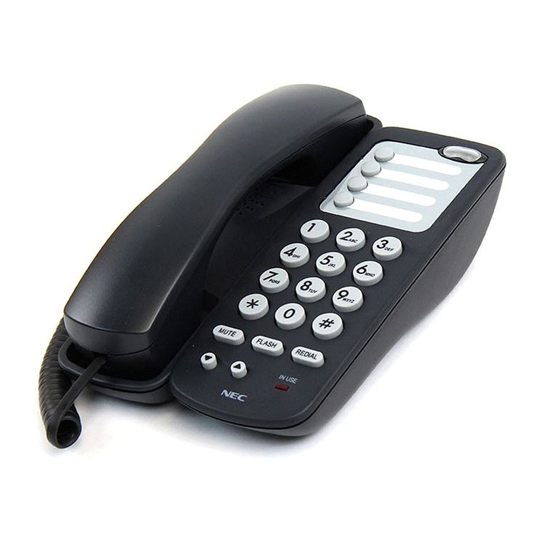
NEC SL1100 User manual

Hardware Manual
A50-031693-003 NA
ISSUE 5.0

Copyright
NEC Corporation reserves the right to change the specifications, functions, or features at any time
without notice.
NEC Corporation has prepared this document for use by its employees and customers. The
information contained herein is the property of NEC Corporation and shall not be reproduced without
prior written approval of NEC Corporation.
Windows is a registered trademark of Microsoft Corporation. Plantronics is a trademark or registered
trademark of Plantronics, Inc. or its subsidiaries in the United States and other countries and is
licensed to NEC Corporation. All other brand names and product names referenced in this document
are trademarks or registered trademarks of their respective companies.
Copyright 2011 - 2015
NEC Corporation
Printed in Japan

TABLE OF CONTENTS
Regulatory
Chapter 1 Introduction
Section 1 GENERAL INFORMATION............................................... 1-1
Section 2 EQUIPMENT LIST............................................................. 1-2
2.1 KSUs and Optional Unit.................................................................. 1-4
2.1.1 IP4[ ]-1228M-B KSU...................................................................... 1-4
2.1.2 IP4[ ]-1228ME-B EXP................................................................... 1-4
2.1.3 IP4WW-EXIFB-C1......................................................................... 1-5
2.1.4 IP4WW-Battery Box...................................................................... 1-5
2.2 Trunk/Extension/ISDN Expansion Interface Cards......................... 1-5
2.2.1 IP4WW-080E-B1........................................................................... 1-5
2.2.2 IP4WW-008E-B1........................................................................... 1-6
2.2.3 IP4WW-000E-B1........................................................................... 1-6
2.2.4 IP4WW-4COIDB-B1...................................................................... 1-6
2.2.5 IP4WW-1PRIU-C1........................................................................ 1-6
2.3 Optional Interface Cards................................................................. 1-7
2.3.1 IP4WW-VOIPDB-C1 .................................................................... 1-7
2.3.2 IP4WW-CFVMS-C1/IP4WW-CFVML-C1 ..................................... 1-7
2.4 Multiline Telephones and Optional Equipment .............................. 1-7
2.4.1 IP4WW-12TXH-B TEL.................................................................. 1-7
2.4.2 IP4WW-24TXH-B TEL.................................................................. 1-7
2.4.3 IP4[ ]-24TIXH-C TEL .................................................................... 1-8
2.4.4 IP4WW-60D DSS-B...................................................................... 1-8
2.4.5 DP-D-1D........................................................................................ 1-8
2.4.6 Wireless Headset Adapter (WHA)................................................. 1-8
2.4.7 ITX-1DE-1W(BK) TEL (V5.0 or higher)......................................... 1-9
2.5 Wireless DECT Telephones........................................................... 1-9
2.5.1 DTL-8R-1 Cordless DECT Telephone.......................................... 1-9
2.5.2 DTL-RPT-[ ] Cordless DECT Telephone Repeater....................... 1-9
2.5.3 ML440 and AP20 Wireless DECT Telephone............................... 1-9
2.6 Call Logging Unit (V3.0 or higher)................................................ 1-10
2.6.1 NEC 1-port Digital Call Logging Unit........................................... 1-10
2.6.2 NEC 1-Port IP Call Logging Unit (V4.0 or higher)....................... 1-10
Section 3 SYSTEM CAPACITY....................................................... 1-11
3.1 System Capacity........................................................................... 1-11
3.2 KSU Capacity............................................................................... 1-13
3.2.1 Expandability of Trunk and Extension (without PRI)................... 1-14
3.2.2 Expandability of Trunk and Extension (with PRI)........................ 1-15
Chapter 2 Installation
Section 1 INSTALLING THE MAIN & EXPANSION KSUs............... 2-1
1.1 Before Installing the KSU(s)........................................................... 2-1
1.1.1 General Precautions..................................................................... 2-1
1.1.2 Preparations.................................................................................. 2-1
ISSUE 5.0 SL1100
Hardware Manual i

1.1.3 Site Requirements......................................................................... 2-1
1.1.4 Environmental Requirements........................................................ 2-2
1.1.5 Unpacking..................................................................................... 2-2
1.2 Installing the Main KSU (1228M-B KSU)....................................... 2-2
1.3 Wall-Mounting the KSU(s).............................................................. 2-3
1.3.1 KSU Dimensions........................................................................... 2-3
1.3.2 Wall Installation of KSU................................................................. 2-4
1.3.3 Mounting Procedure of KSU......................................................... 2-6
1.4 Installing the Expansion KSU(s)..................................................... 2-9
1.4.1 General......................................................................................... 2-9
1.4.2 Unpacking (EXIFB-C1).................................................................. 2-9
1.4.3 Connectors Location (EXIFB-C1).................................................. 2-9
1.4.4 Installing the EXIFB-C1 PCB........................................................ 2-9
1.4.5 KSUs Inter-connection................................................................ 2-12
1.5 Grounding and AC Cabling........................................................... 2-13
1.5.1 Grounding the KSU..................................................................... 2-13
1.5.2 AC Power Requirement.............................................................. 2-14
1.5.3 AC Power Cord........................................................................... 2-14
1.6 Trunk/Extension Cabling............................................................... 2-15
1.6.1 General....................................................................................... 2-15
1.6.2 Precautions for Cabling............................................................... 2-15
1.6.3 Trunk Cabling.............................................................................. 2-15
1.6.4 Extension Cabling....................................................................... 2-15
1.6.5 Cable Routing and Clamping...................................................... 2-18
Section 2 INSTALLING THE EXTERNAL BACKUP BATTERY..... 2-20
2.1 General......................................................................................... 2-20
2.2 Unpacking..................................................................................... 2-20
2.3 Battery Box Dimensions .............................................................. 2-21
2.4 Battery Specifications................................................................... 2-21
2.5 Battery Installation........................................................................ 2-21
2.6 Mounting the IP4WW-Battery Box................................................ 2-27
2.6.1 Floor-Mounting the IP4WW-Battery Box..................................... 2-27
2.6.2 Wall-Mounting the IP4WW-Battery Box...................................... 2-29
2.6.3 Mounting One KSU on the Battery Box....................................... 2-33
2.7 IP4WW-Battery Box to KSU Connection...................................... 2-36
2.8 IP4WW-Battery Box Fuse Replacement....................................... 2-37
Section 3 INSTALLING THE EXPANSION INTERFACE
CARDS......................................................................... 2-42
3.1 General......................................................................................... 2-42
3.2 Unpacking..................................................................................... 2-42
3.3 Mounting the Expansion Interface Card....................................... 2-43
3.3.1 Mounting the 080E-B1/008E-B1/000E-B1/1PRIU-C1 PCBs....... 2-43
3.3.2 Mounting the 4COIDB PCB......................................................... 2-48
3.4 Cabling and Setting the Expansion Interface Card....................... 2-50
3.4.1 Cabling IP4WW-080E-B1............................................................ 2-51
3.4.2 Cabling IP4WW-008E-B1............................................................ 2-52
3.4.3 Cabling IP4WW-000E-B1 ........................................................... 2-53
3.4.4 Cabling and Setting IP4WW-4COIDB-B1................................... 2-53
3.4.5 Cabling and Setting IP4WW-1PRIU-C1...................................... 2-54
3.5 Power Failure Transfer (4COIDB-B1 only)................................... 2-57
SL1100 ISSUE 5.0
ii Hardware Manual

3.5.1 General....................................................................................... 2-57
Section 4 INSTALLING THE OPTIONAL INTERFACE CARDS..... 2-59
4.1 VoIP Card (VOIPDB-C1) ............................................................. 2-59
4.1.1 General....................................................................................... 2-59
4.1.2 Unpacking................................................................................... 2-59
4.1.3 Installing the VOIPDB-C1 PCB................................................... 2-59
4.1.4 LED Indication............................................................................. 2-63
4.2 Installing the CF Card (CFVMS/CFVML)...................................... 2-63
Section 5 INSTALLING THE MULTILINE TELEPHONES
AND OPTIONAL TERMINALS.................................... 2-65
5.1 Installing the Multiline Telephones................................................ 2-65
5.1.1 Location of Controls.................................................................... 2-65
5.1.2 Multiline Telephone Legs Adjustment......................................... 2-66
5.1.3 Wall-Mounting the Multiline Telephone ...................................... 2-68
5.2 Install the IP Multiline Telephone (IP4WW-24TIXH-C1 TEL)....... 2-70
5.2.1 System Connection..................................................................... 2-70
5.2.2 Installing the IP Multiline Telephone........................................... 2-70
5.2.3 Applying Power to the IP Multiline Telephone............................. 2-71
5.3 Installing the DSS Console........................................................... 2-71
5.3.1 DSS Console Leg Adjustment..................................................... 2-71
5.3.2 Wall-Mounting the DSS Console................................................. 2-73
5.4 Installing the Headset................................................................... 2-74
5.5 Installing the Doorphone Box........................................................ 2-75
5.5.1 Wall-Mounting the Doorphone.................................................... 2-75
5.5.2 Connecting the Doorphone......................................................... 2-77
5.5.3 Doorphone Interface Specifications............................................ 2-77
5.6 Installing the Door Unlock Devices............................................... 2-77
5.7 Installing the External Paging Speaker/External MOH/BGM
Sources.................................................................................. 2-79
5.7.1 Connecting the Audio Equipment................................................ 2-79
5.7.2 External Paging Output Specifications........................................ 2-79
5.7.3 BGM/External MOH Source Input Specifications........................ 2-80
5.8 SMDR (Station Message Detail Recording)................................. 2-80
5.8.1 General....................................................................................... 2-80
5.9 Wireless Headset Adapter (WHA)................................................ 2-80
5.9.1 Installing the Wireless Headset Adapter.................................... 2-80
5.9.2 Operation.................................................................................... 2-83
5.9.3 General Notes............................................................................. 2-83
5.9.4 Recommended Model................................................................. 2-83
5.10 Installing the ITX-1DE-1W(BK) TEL (V5.0 or higher)................. 2-84
5.10.1 Connecting the Phone............................................................... 2-84
5.10.2 Location of Controls.................................................................. 2-84
5.10.3 System Connection................................................................... 2-86
Section 6 INSTALLING WIRELESS DECT TELEPHONES............ 2-87
6.1 Installing the DTL-8R-1 Cordless DECT Telephone..................... 2-87
6.1.1 Selecting a Location.................................................................... 2-88
6.1.2 Installation Precautions............................................................... 2-88
6.1.3 Connecting the Telephone Cords............................................... 2-88
6.1.4 Applying Power to the Charging Unit.......................................... 2-89
ISSUE 5.0 SL1100
Hardware Manual iii

6.1.5 Mounting the Base to a Standard Wall Plate.............................. 2-90
6.1.6 Mounting the Base Directly to the Wall....................................... 2-92
6.1.7 Wall Mounting the Charging Unit................................................ 2-93
6.1.8 Attaching and Removing the Belt Clip......................................... 2-95
6.1.9 Installing the Handset Battery Pack............................................ 2-95
6.1.10 Charging Batteries.................................................................... 2-96
6.1.11 Charging Spare Battery Packs.................................................. 2-97
6.2 Installing the DTL-RPT-1 Cordless DECT Telephone
REPEATER............................................................................ 2-97
6.2.1 Setting Up Your Repeater........................................................... 2-99
6.2.2 Installing the Repeater.............................................................. 2-100
6.2.3 Troubleshooting Chart............................................................... 2-104
6.2.4 Turning on the Verification Tone............................................... 2-104
6.2.5 Maintenance.............................................................................. 2-104
6.3 Installing the DTL-RPT-2 Cordless DECT Telephone
REPEATER.......................................................................... 2-104
6.3.1 Configurations........................................................................... 2-105
6.3.2 Setting Up Your Repeater......................................................... 2-107
6.3.3 Installing The AC Adapter......................................................... 2-109
6.3.4 Activate Registration Mode On Base........................................ 2-109
6.3.5 Positioning the Repeater(s)...................................................... 2-110
6.3.6 Installing The Repeater............................................................. 2-113
6.3.7 Troubleshooting Chart............................................................... 2-113
6.3.8 Maintenance.............................................................................. 2-113
6.4 Installing the ML440 and AP20 Wireless DECT Telephone....... 2-113
6.4.1 Connecting the Base Station..................................................... 2-113
6.4.2 Wall Mounting the Base Station................................................ 2-115
6.4.3 Handset and Charger................................................................ 2-116
Section 7 INSTALLING OPTIONAL EQUIPMENT (V3.0 OR
HIGHER).................................................................... 2-120
7.1 NEC Digital Call Logger.............................................................. 2-120
7.1.1 NEC 1-Port Digital Logging Unit................................................ 2-120
7.2 NEC IP Call Logger (V4.0 or higher).......................................... 2-123
7.2.1 NEC 1-Port IP Call Logging Unit............................................... 2-123
7.3 NEC Digital Player Requirements............................................... 2-130
7.3.1 Hardware and Software Requirements..................................... 2-130
7.4 NEC Digital Player/Recorder Installation.................................... 2-131
7.4.1 Installing the NEC Digital Player............................................... 2-131
Chapter 3 System Start Up
Section 1 SYSTEM START UP.......................................................... 3-1
1.1 Before Starting Up the System....................................................... 3-1
1.2 Starting Up the System................................................................... 3-1
1.2.1 Perform a Cold Start..................................................................... 3-2
1.2.2 Perform a Hot Start....................................................................... 3-3
Section 2 PROGRAMMING MODE .................................................. 3-5
2.1 Entering the Programming Mode.................................................... 3-5
2.2 Exiting the Programming Mode...................................................... 3-5
2.3 Saving (Backup) the Customer Data.............................................. 3-6
SL1100 ISSUE 5.0
iv Hardware Manual

2.4 Loading the Customer Data............................................................ 3-6
Section 3 SYSTEM SHUT DOWN..................................................... 3-8
3.1 Powering Off the System................................................................ 3-8
3.2 Resetting the System...................................................................... 3-8
Chapter 4 Maintenance
Section 1 FUSE REPLACEMENT..................................................... 4-1
1.1 Replacing the Fuse......................................................................... 4-1
Section 2 LITHIUM BATTERY REPLACEMENT.............................. 4-4
2.1 General........................................................................................... 4-4
2.2 Lithium Battery Specification.......................................................... 4-4
2.3 Replacing the Lithium Battery......................................................... 4-5
Section 3 MAIN SOFTWARE UPGRADING...................................... 4-9
3.1 General........................................................................................... 4-9
3.2 Before Upgrading the Main Software.............................................. 4-9
3.3 Main Software Version Confirmation.............................................. 4-9
3.4 Upgrading the Main Software....................................................... 4-10
Section 4 LED INDICATIONS.......................................................... 4-14
Chapter 5 Specifications
Section 1 SYSTEM CAPACITY......................................................... 5-1
Section 2 SYSTEM SPECIFICATIONS............................................. 5-3
2.1 General Precautions....................................................................... 5-3
2.2 Environmental Requirements......................................................... 5-3
2.3 Operating Conditions...................................................................... 5-3
2.4 Site Requirements.......................................................................... 5-3
2.5 AC Power Requirement.................................................................. 5-3
2.6 Electrical Specifications <Power Supply> (KSU)............................ 5-4
2.7 CPU................................................................................................ 5-4
2.8 Traffic Capacity............................................................................... 5-5
2.9 IP Terminal Power Chart................................................................ 5-5
2.10 IEEE802.af Class Specification.................................................... 5-5
2.11 SLT Ring Signal Specification (V5.0 or higher)............................ 5-5
2.12 Mechanical Specifications............................................................ 5-5
2.13 Optional Unit Mechanical Specifications....................................... 5-6
2.14 Doorphone Interface Specifications.............................................. 5-6
2.15 General Purpose/Door Unlock Relay Specifications.................... 5-6
2.16 External Paging Output Specifications......................................... 5-7
2.17 BGM/ExMOH Source Input Specifications................................... 5-7
2.18 External Sensor Device Interface Specifications.......................... 5-7
2.19 CPU Card LAN Port Specifications............................................... 5-7
2.20 Cabling Requirements ................................................................. 5-7
2.21 Cable Requirements..................................................................... 5-8
ISSUE 5.0 SL1100
Hardware Manual v

LIST OF TABLES
Table 1-1 System Capacity ............................................................................................. 1-11
Table 2-1 KSU Packing List............................................................................................... 2-2
Table 2-2 Items on the CPU card...................................................................................... 2-3
Table 2-3 EXIFB-C1 Packing List...................................................................................... 2-9
Table 2-4 Connectors of EXIFB-C1................................................................................... 2-9
Table 2-5 Power Requirement......................................................................................... 2-14
Table 2-6 RJ61 Cable Connector Pin-Outs (J101-J103)................................................. 2-18
Table 2-7 IP4WW-Battery Box Packing List.................................................................... 2-20
Table 2-8 Battery Specifications...................................................................................... 2-21
Table 2-9 Expansion Cards............................................................................................. 2-42
Table 2-10 Expansion Card Packing List......................................................................... 2-42
Table 2-11 RJ-61 Digital Connector Pin-Outs (J101, J102) ............................................ 2-52
Table 2-12 RJ-61 Analog Pin-Outs (J101, J102) ............................................................ 2-53
Table 2-13 RJ-61 CO/PF Pin-Outs (J2, J3)..................................................................... 2-54
Table 2-14 RJ-45 PRI Pin-Outs (S-Bus, T-Bus) ............................................................. 2-55
Table 2-15 Switch Setting of 1PRIU-C1........................................................................... 2-55
Table 2-16 LED Indication............................................................................................... 2-56
Table 2-17 T1 LED Indications........................................................................................ 2-57
Table 2-18 VOIPDB-C1 Packing List............................................................................... 2-59
Table 2-19 VOIPDB LED Indications............................................................................... 2-63
Table 2-20 Operation of VOIPDB LED Indications.......................................................... 2-63
Table 2-21 Multiline Telephone Functions (12TXH/24TXH/24TIXH (IP)) ....................... 2-65
Table 2-22 Doorphone Interface Specifications............................................................... 2-77
Table 2-23 RJ-61 General Purpose/Door Unlock Relay Control Connector (J7)............. 2-78
Table 2-24 General Purpose/Door Unlock Relay Specifications..................................... 2-78
Table 2-25 External Paging Output Specifications.......................................................... 2-79
Table 2-26 BGM/External MOH Source Input Specifications.......................................... 2-80
Table 2-27 Location of Controls (Front Side)................................................................... 2-85
Table 2-28 Location of Controls (Back Side)................................................................... 2-85
Table 2-29 Repeater LED Patterns................................................................................ 2-108
Table 2-30 Base Station LEDs States and Meanings.................................................... 2-115
Table 3-1 Start Up Method................................................................................................. 3-1
Table 4-1 Status LEDs..................................................................................................... 4-12
Table 4-2 CPU LED Indications....................................................................................... 4-14
Table 5-1 System Capacity ............................................................................................... 5-1
Table 5-2 Operating Conditions......................................................................................... 5-3
Table 5-3 Power Requirement........................................................................................... 5-3
Table 5-4 Electrical Specifications of KSU......................................................................... 5-4
Table 5-5 IP Terminal Power Chart................................................................................... 5-5
Table 5-6 IEEE802.af Class Specification......................................................................... 5-5
Table 5-7 Mechanical Specifications................................................................................. 5-5
Table 5-8 Optional Unit Mechanical Specifications............................................................ 5-6
Table 5-9 Doorphone Interface Specifications................................................................... 5-6
Table 5-10 General Purpose/Door Unlock Relay Specifications....................................... 5-6
Table 5-11 External Paging Output Specifications............................................................ 5-7
Table 5-12 BGM/External MOH Source Input Specifications............................................ 5-7
Table 5-13 External Sensor Device Interface Specifications............................................. 5-7
Table 5-14 CPU Card LAN Port Specifications.................................................................. 5-7
Table 5-15 Cable Requirements........................................................................................ 5-8
SL1100 ISSUE 5.0
vi Hardware Manual

LIST OF FIGURES
Figure 1-1 System Configuration (V3.5 or higher)............................................................. 1-1
Figure 1-2 System Image ................................................................................................ 1-13
Figure 1-3 Maximum KSU Capacity - Expandability of Trunk and Extension
(without PRI) ............................................................................................ 1-14
Figure 1-4 Maximum KSU Capacity - Expandability of Trunk and Extension (with
PRI) .......................................................................................................... 1-15
Figure 2-1 CPU Card Location........................................................................................... 2-3
Figure 2-2 Dimension of the Main and Expansion KSU..................................................... 2-4
Figure 2-3 Vertical Arrangement of KSUs ......................................................................... 2-5
Figure 2-4 Horizontal Arrangement of KSUs .................................................................... 2-6
Figure 2-5 Wall-Mounting Template................................................................................... 2-6
Figure 2-6 Screw Positions................................................................................................ 2-7
Figure 2-7 Sub-Cover Slide-out......................................................................................... 2-7
Figure 2-8 Removing the Sub-Cover................................................................................. 2-8
Figure 2-9 Sub-Cover Open Position................................................................................. 2-8
Figure 2-10 Mounting the KSU.......................................................................................... 2-8
Figure 2-11 Connectors of EXIFB-C1................................................................................ 2-9
Figure 2-12 Removing the Sub-Cover ............................................................................ 2-10
Figure 2-13 Removing the Main-Cover ........................................................................... 2-10
Figure 2-14 EXIFB-C1 PCB Installation........................................................................... 2-11
Figure 2-15 Removing the Plastic Knockouts.................................................................. 2-11
Figure 2-16 Replacing the Main-Cover............................................................................ 2-11
Figure 2-17 Connection of KSUs .................................................................................... 2-12
Figure 2-18 Installing Ferrite Core................................................................................... 2-13
Figure 2-19 ETH Lug....................................................................................................... 2-13
Figure 2-20 AC Power Cord............................................................................................. 2-15
Figure 2-21 Digital Extension Cabling.............................................................................. 2-16
Figure 2-22 Analog Extension Cabling............................................................................ 2-17
Figure 2-23 Cabling......................................................................................................... 2-18
Figure 2-24 Sub-Cover.................................................................................................... 2-19
Figure 2-25 Dimension of the IP4WW-Battery Box.......................................................... 2-21
Figure 2-26 Removing the Front Cover .......................................................................... 2-22
Figure 2-27 Disconnect Battery Connection Cable.......................................................... 2-22
Figure 2-28 Batt Stopper.................................................................................................. 2-23
Figure 2-29 Pulling out the Battery Tray ......................................................................... 2-23
Figure 2-30 Remove the Battery Tray Bracket ............................................................... 2-24
Figure 2-31 Battery Installation........................................................................................ 2-24
Figure 2-32 Connecting the Battery Cables..................................................................... 2-25
Figure 2-33 Installation of Battery Tray Cover................................................................. 2-25
Figure 2-34 Inserting the Battery Tray............................................................................. 2-26
Figure 2-35 Secure Batt Stopper Bracket........................................................................ 2-26
Figure 2-36 Connecting the Battery Connection Cable................................................... 2-27
Figure 2-37 Installation of Front Cover............................................................................ 2-27
Figure 2-38 Bases and Support of the Battery Box......................................................... 2-28
Figure 2-39 Floor-Mount Spacing Guide.......................................................................... 2-28
Figure 2-40 Mounting the Battery Box............................................................................. 2-29
Figure 2-41 Securing the Battery Box.............................................................................. 2-29
Figure 2-42 Assemble Battery Box Base......................................................................... 2-30
Figure 2-43 Wall-Mount Spacing Guide........................................................................... 2-31
Figure 2-44 Removing the Front Cover .......................................................................... 2-32
Figure 2-45 Mounting the Battery Box............................................................................. 2-32
ISSUE 5.0 SL1100
Hardware Manual vii

Figure 2-46 Securing the Battery Box.............................................................................. 2-33
Figure 2-47 Removing the Front Cover .......................................................................... 2-33
Figure 2-48 Removing the L-Bracket .............................................................................. 2-34
Figure 2-49 Securing the L-Bracket and WM Hook......................................................... 2-35
Figure 2-50 Attaching the KSU........................................................................................ 2-35
Figure 2-51 KSU Mounting on Battery Box...................................................................... 2-36
Figure 2-52 Sub-Cover Open and Hold........................................................................... 2-36
Figure 2-53 Connecting Battery Cable............................................................................. 2-37
Figure 2-54 Removing the Front Cover .......................................................................... 2-38
Figure 2-55 Disconnecting the Battery Connection Cable............................................... 2-38
Figure 2-56 Loosen the Fuse Unit Screw........................................................................ 2-39
Figure 2-57 Replacing the Fuse....................................................................................... 2-39
Figure 2-58 Install the Fuse Unit...................................................................................... 2-39
Figure 2-59 Securing the Fuse Unit................................................................................. 2-40
Figure 2-60 Connect Battery Connection Cable.............................................................. 2-40
Figure 2-61 Installation of the Front Cover...................................................................... 2-41
Figure 2-62 Removing the Sub-Cover ............................................................................ 2-43
Figure 2-63 Removing the Main-Cover ........................................................................... 2-44
Figure 2-64 Mounting the 1st Expansion Interface Card................................................. 2-44
Figure 2-65 Mounting the 2nd Expansion Interface Card................................................ 2-45
Figure 2-66 Mounting the 3rd Expansion Interface Card................................................. 2-46
Figure 2-67 Mounting Three Expansion Interface Cards................................................. 2-47
Figure 2-68 Plastic Knockouts......................................................................................... 2-47
Figure 2-69 Replacing the Main-cover............................................................................. 2-48
Figure 2-70 Plastic Knockouts on 084M-B1/080E-B1/008E-B1/000E-B1........................ 2-48
Figure 2-71 Installing the 4COIDB-B1............................................................................. 2-49
Figure 2-72 Mounting the 4COIDB-B1 into the KSU........................................................ 2-50
Figure 2-73 Replacing the Main-Cover............................................................................ 2-50
Figure 2-74 Connectors of 080E-B1................................................................................ 2-51
Figure 2-75 Connectors of 008E-B1................................................................................ 2-52
Figure 2-76 Connectors of 4COIDB-B1........................................................................... 2-53
Figure 2-77 Connector of 1PRIU-C1................................................................................ 2-54
Figure 2-78 Switches and LEDs Location of 1PRIU-C1.................................................. 2-56
Figure 2-79 1PRIU-C1 LED Indication Pattern of Layer 1 on T1 Unit.............................. 2-57
Figure 2-80 Removing the Sub-Cover ............................................................................ 2-59
Figure 2-81 Removing the Main-Cover ........................................................................... 2-60
Figure 2-82 Removing the CPU Card ............................................................................. 2-60
Figure 2-83 Installing the VOIPDB-C1 PCB..................................................................... 2-61
Figure 2-84 Installing the CPU Card................................................................................ 2-61
Figure 2-85 Removing the Plastic Knockout and Replacing the Main-Cover.................. 2-62
Figure 2-86 Connecting a LAN Cable.............................................................................. 2-62
Figure 2-87 Location of LEDs.......................................................................................... 2-63
Figure 2-88 Installing the CF Card................................................................................... 2-64
Figure 2-89 Multiline Telephone (12TXH/24TXH/24TIXH (IP))........................................ 2-65
Figure 2-90 Leg Setting for Low Position......................................................................... 2-66
Figure 2-91 Cabling of Multiline Telephone..................................................................... 2-66
Figure 2-92 Setting for High Position............................................................................... 2-67
Figure 2-93 Leg Setting for High Position........................................................................ 2-67
Figure 2-94 Cabling for Wall-Mount................................................................................. 2-68
Figure 2-95 Wall-Mount Unit - 24TIXH-C......................................................................... 2-68
Figure 2-96 Hook-Switch Hanger..................................................................................... 2-69
Figure 2-97 Wall-Mount Screw Guide.............................................................................. 2-69
Figure 2-98 Mounting the Multiline Telephone................................................................. 2-69
SL1100 ISSUE 5.0
viii Hardware Manual

Figure 2-99 IP Multiline Telephone Connection............................................................... 2-70
Figure 2-100 IP Multiline Telephone Connectors............................................................. 2-70
Figure 2-101 Low Position Setting................................................................................... 2-71
Figure 2-102 Cabling of DSS........................................................................................... 2-72
Figure 2-103 Leg Stopper of DSS Console..................................................................... 2-72
Figure 2-104 High Position Setting.................................................................................. 2-73
Figure 2-105 Cabling for Wall-Mount............................................................................... 2-73
Figure 2-106 Wall-Mount Screw Guide............................................................................ 2-74
Figure 2-107 Mounting the DSS...................................................................................... 2-74
Figure 2-108 Headset Socket (2-wire Multiline Telephone)............................................. 2-75
Figure 2-109 Headset Socket (IP Multiline Telephone)................................................... 2-75
Figure 2-110 Doorphone Box and Bracket...................................................................... 2-76
Figure 2-111 Doorphone.................................................................................................. 2-76
Figure 2-112 Connecting the Doorphone......................................................................... 2-77
Figure 2-113 Connecting the Door Unlock Device........................................................... 2-78
Figure 2-114 Connecting Audio Equipment..................................................................... 2-79
Figure 2-115 Connecting a PC for SMDR........................................................................ 2-80
Figure 2-116 Headset Socket (2-wire Multiline Telephone)............................................. 2-82
Figure 2-117 Headset Socket (IP Multiline Telephone)................................................... 2-82
Figure 2-118 Telephone Line Socket (2-wire Multiline Telephone)................................. 2-83
Figure 2-119 Telephone Line Socket (IP Multiline Telephone)........................................ 2-83
Figure 2-120 SIP Phone - Front View.............................................................................. 2-84
Figure 2-121 SIP Phone - Back View.............................................................................. 2-85
Figure 2-122 System Connection.................................................................................... 2-86
Figure 2-123 Cordless DECT Telephone (DTL-8R-1)..................................................... 2-87
Figure 2-124 System Overview........................................................................................ 2-87
Figure 2-125 Connecting Telephone Cords to the Telephone Jack................................ 2-88
Figure 2-126 Connecting the DTL-8R-1 Cordless DECT to the Multiline Terminal......... 2-89
Figure 2-127 Applying Power to the Charging Unit.......................................................... 2-89
Figure 2-128 Polarized Plug............................................................................................ 2-90
Figure 2-129 Attaching the Wall Mount Stand to the Base Unit....................................... 2-90
Figure 2-130 Placing the AC Adapter Cord Inside the Wall Mount Stand....................... 2-91
Figure 2-131 Placing the Base Unit on the Posts of the Wall Plate................................. 2-91
Figure 2-132 Plugging the AC Adapter into the AC Wall Outlet....................................... 2-92
Figure 2-133 Inserting Screws into the Wall for Wall Mounting the Telephone............... 2-92
Figure 2-134 Placing the Telephone Cords Inside the Wall Mount Stand....................... 2-93
Figure 2-135 Attaching the Wall Mount Unit to the Wall.................................................. 2-93
Figure 2-136 Inserting Screws for Wall Mounting............................................................ 2-94
Figure 2-137 Wrapping the AC Adapter Cord Around the Strain Relief........................... 2-94
Figure 2-138 Placing the Charging Unit on the Wall........................................................ 2-94
Figure 2-139 Attaching the Belt Clip to the Handset........................................................ 2-95
Figure 2-140 Removing the Belt Clip............................................................................... 2-95
Figure 2-141 Removing the Battery Cover...................................................................... 2-96
Figure 2-142 Replacing the Battery Pack........................................................................ 2-96
Figure 2-143 Replacing the Battery Cover....................................................................... 2-96
Figure 2-144 Cordless DECT Telephone Repeater DTL-RPT-1..................................... 2-97
Figure 2-145 Single Repeater Attached to Base............................................................. 2-98
Figure 2-146 Six Repeaters Attached to Base................................................................. 2-98
Figure 2-147 Daisy-Chain Layout.................................................................................... 2-99
Figure 2-148 Base Coverage Area................................................................................ 2-101
Figure 2-149 Incorrect Installation................................................................................. 2-102
Figure 2-150 Base Coverage Area................................................................................ 2-103
Figure 2-151 Daisy-Chain Layout.................................................................................. 2-103
ISSUE 5.0 SL1100
Hardware Manual ix

Figure 2-152 Single Repeater Attached to Base........................................................... 2-105
Figure 2-153 Six Repeaters Attached to Base............................................................... 2-106
Figure 2-154 Daisy-Chain Layout.................................................................................. 2-106
Figure 2-155 Combo Star and Daisy-Chain Layout....................................................... 2-107
Figure 2-156 Back View of the DTL-RPT-2 Repeater.................................................... 2-108
Figure 2-157 Removing the Adapter Cover................................................................... 2-109
Figure 2-158 Threading the AC Adapter Cord............................................................... 2-109
Figure 2-159 Mapping the Base’s Coverage Area......................................................... 2-111
Figure 2-160 Incorrect Installation................................................................................. 2-112
Figure 2-161 Correct Repeater Installation.................................................................... 2-112
Figure 2-162 Base Station Front and Back View........................................................... 2-114
Figure 2-163 Connecting the Base Station.................................................................... 2-115
Figure 2-164 Base Mounting Dimensions...................................................................... 2-116
Figure 2-165 Handset Front View.................................................................................. 2-117
Figure 2-166 Charger Top View..................................................................................... 2-118
Figure 2-167 Installing the Handset Battery................................................................... 2-118
Figure 2-168 Inserting Handset into the Charger........................................................... 2-119
Figure 2-169 1-Port Digital Logging Unit........................................................................ 2-120
Figure 2-170 VSR Connection Configuration................................................................. 2-121
Figure 2-171 Hardware Update Welcome Screen......................................................... 2-122
Figure 2-172 Hardware Update Screen – Installation Options...................................... 2-122
Figure 2-173 Hardware Installation – Logo Testing Screen........................................... 2-123
Figure 2-174 1-Port IP Call Logging Unit....................................................................... 2-124
Figure 2-175 IP Call Logger Configuration.................................................................... 2-125
Figure 2-176 IP Call Logger – Hardware Update Wizard.............................................. 2-126
Figure 2-177 IP Tap – InstallShield Wizard................................................................... 2-127
Figure 2-178 IP Tap – License Agreement.................................................................... 2-127
Figure 2-179 IP Tap – Choose Destination Location..................................................... 2-128
Figure 2-180 IP Tap – Choose Data Folder................................................................... 2-128
Figure 2-181 IP Tap – Ready to Install the Program..................................................... 2-129
Figure 2-182 IP Tap – Setup Status.............................................................................. 2-129
Figure 2-183 IP Tap – Wizard Complete....................................................................... 2-130
Figure 2-184 Dterm VSR Player – Welcome Screen..................................................... 2-132
Figure 2-185 Dterm Player – License Agreement.......................................................... 2-132
Figure 2-186 Dterm VSR Player – Choose Destination Location.................................. 2-133
Figure 2-187 Dterm VSR Player – Choose Data Folder................................................ 2-133
Figure 2-188 Dterm VSR Player – Ready to Install the Program................................... 2-134
Figure 2-189 Dterm VSR Player – Wizard Complete Screen........................................ 2-134
Figure 3-1 Lithium Battery Protection Sheet...................................................................... 3-1
Figure 3-2 Power Switch Location..................................................................................... 3-2
Figure 3-3 Load Button (S1) Location................................................................................ 3-2
Figure 3-4 Status LED (D5) and RUN LED Location......................................................... 3-3
Figure 3-5 Display Indication (Idle) ................................................................................... 3-3
Figure 3-6 Entering Programming Mode Display 1............................................................ 3-5
Figure 3-7 Entering Programming Mode Display 2............................................................ 3-5
Figure 3-8 Exiting the Programming Mode Display 1........................................................ 3-5
Figure 3-9 Exiting Programming Mode Display 2.............................................................. 3-5
Figure 3-10 Inserting the CF card...................................................................................... 3-6
Figure 3-11 PRG90-03 Display.......................................................................................... 3-6
Figure 3-12 PRG90-04 Display.......................................................................................... 3-6
Figure 3-13 Inserting the CF card...................................................................................... 3-7
Figure 3-14 PRG90-04 Display.......................................................................................... 3-7
Figure 3-15 Next PRG Display........................................................................................... 3-7
SL1100 ISSUE 5.0
x Hardware Manual

Figure 3-16 Power Switch Location................................................................................... 3-8
Figure 4-1 Removing the Sub-Cover................................................................................. 4-1
Figure 4-2 Removing the Main-Cover................................................................................ 4-2
Figure 4-3 Exchanging the Fuse........................................................................................ 4-2
Figure 4-4 Replacing the Main-Cover................................................................................ 4-3
Figure 4-5 Warning of Low Battery.................................................................................... 4-4
Figure 4-6 Removing the Sub-Cover................................................................................. 4-5
Figure 4-7 Disconnecting the AC Power Cord................................................................... 4-5
Figure 4-8 Removing the Main-Cover................................................................................ 4-6
Figure 4-9 Removing the CPU Card.................................................................................. 4-6
Figure 4-10 Location of Lithium Battery Socket................................................................. 4-7
Figure 4-11 Removing the Lithium Battery........................................................................ 4-7
Figure 4-12 Inserting the Lithium Battery........................................................................... 4-7
Figure 4-13 Installing the CPU Card.................................................................................. 4-8
Figure 4-14 Display of Multiline Telephone........................................................................ 4-9
Figure 4-15 Removing the Sub-Cover............................................................................. 4-10
Figure 4-16 Removing the Main-Cover............................................................................ 4-11
Figure 4-17 Inserting the CF card.................................................................................... 4-11
Figure 4-18 LOAD Button (S1) Location.......................................................................... 4-12
Figure 4-19 Removing the CF card.................................................................................. 4-12
ISSUE 5.0 SL1100
Hardware Manual xi

MEMO
SL1100 ISSUE 5.0
xii Hardware Manual

Regulatory
GENERAL INFORMATION
This equipment complies with Part 68 of the FCC Rules and the requirements adopted by the ACTA.
On the equipment is a label that contains, among other information, a product identifier in the format:
US:AAAEQ##TXXXX. If requested, this number must be provided to the telephone company.
The telephone company may make changes in its technical operations and procedures. When such
changes affect the compatibility or use of the SL1100 system, the telephone company is required to
give adequate notice of the changes in order for you to maintain uninterrupted service.
The REN is used to determine the number of devices that may be connected to a telephone line.
Excessive RENs on a telephone line may result in the devices not ringing in response to an incoming
call. In most, but not all areas, the sum of RENs should not exceed five (5.0). To be certain of the
number of devices that may be connected to a line, as determined by the total RENs, contact the local
telephone company. For products approved after July 23, 2001, the REN for this product is the
product identifier in format: US:AAAEQ##TXXXX. The digits represented by ## are the REN without a
decimal point (e.g., 03 is a REN of 0.3).
Connection to party line service is subject to state tariffs. Contact the state public utilities commission,
public service commission or corporation commission for information.
For single and two-line equipment that connects to the telephone network via a plug and jack, the plug
and jack used with this equipment must comply with FCC Part 68 rules.
A plug and jack used to connect this equipment to the premises wiring and telephone network must
comply with the applicable FCC Part 68 rules and requirements adopted by the ACTA. A compliant
telephone cord and modular plug is provided with this product. It must be connected to a compatible
modular jack that is also compliant.
TELEPHONE/SERVICE PROVIDER COMPANY NOTIFICATION
Before connecting this telephone system to the telephone network, the following information must be
provided to the telephone company:
1. Your telephone number.
2. FCC registration number:
• When the system is to be installed as a Key Function system (no dial access to Trunk Groups/
Route Advance Blocks), use the following number:
US:NIFKF10BSL1100
• When the system is to be installed as a Multifunction system, use the following number:
US:NIFMF10BSL1100
• When the system is to be installed as a PBX system, use the following number:
US:NIFPF10BSL1100
Ringer Equivalence Number (REN): 1.0B
USOC jacks required: RJ11C, RJEX, RJ2FX, RJ2HX, RJ48C, RJ21X
INCIDENCE OF HARM
If this equipment causes harm to the telephone network, the telephone company will notify you in
advance that temporary discontinuance of service may be required. But if advance notice is not
practical, the telephone company will notify the customer as soon as possible. Also, you will be
advised of your right to file a complaint with the FCC if you believe it is necessary.
ISSUE 5.0 SL1100
Hardware Manual R-1

The telephone company may make changes in its facilities, equipment, operations or procedures that
could affect the operation of the equipment. If this happens, the telephone company will provide
advance notice in order for you to make necessary modifications to maintain interrupted service.
REPAIR SERVICE REQUIREMENTS
If the equipment is causing harm to the telephone network, the telephone company may request that
you disconnect the equipment until the problem is resolved.
If equipment malfunctions, all repairs must be performed by an authorized agent of NEC Corporation
of America or by NEC Corporation of America. The user requiring service is responsible for reporting
the need for service to a NEC Corporation of America authorized agent or to NEC Corporation of
America.
PRIVATE (LEASED) LINES
For Private (Leased) Line (Analog Data Format) equipment, type JM8 jack is required. Refer to ATIS
Technical Report No. 5 for details on this connector.
The Facility Interface Code (FIC) associated with each private line application represents the type of
service that will be provided by the telephone company. The user instructions must contain a detailed
list of private line ports and the associated FICs for which the equipment has been approved. In
addition, the Service Order Code (SOC) must also be included for analog systems. The SOC indicates
the degree of network protection provided by the equipment,.
For Private (Leased) Line (Digital Format) equipment, in addition to the general requirements for all
equipment, certain digital connections require that an encoded analog content and billing protection
affidavit be provided the telephone company. Customer instructions must contain information on the
preparation and submission of the affidavit.
To comply with state tariffs, the telephone company must be given notification prior to connection. In
some states, the state public utility commission, public service commission or corporation commission
must give prior approval of connection.
TOLL RESTRICTION AND LEAST COST ROUTING EQUIPMENT
The consumer/purchaser/supplier instructions accompanying this equipment and/or software features
must contain the following notice:
• The software contained in the SL1100 to allow user access to the network must be upgraded to
recognize newly established network area codes and exchange codes as they are placed into
service.
• Failure to upgrade the premises systems or peripheral equipment to recognize the new codes as
they are established will restrict the customer and the customer's employees from gaining access to
the network and these codes.
DIRECT INWARD DIALING
ALLOWING THIS EQUIPMENT TO BE OPERATED IN SUCH A MANNER AS TO NOT PROVIDE
FOR PROPER ANSWER SUPERVISION IS A VIOLATION OF PART 68 OF THE FCC RULES.
Direct Inward Dialing (DID) must contain the following:
Proper Answer Supervision is when:
SL1100 ISSUE 5.0
R-2 Regulatory

• This equipment returns answer supervision to the Public Switched Telephone Network (PSTN)
when Direct Inward Dialing (DID) calls are:
- Answered by the called station.
- Answered by the Attendant.
- Routed to a recorded announcement that can be administered by the Customer Premise
Equipment (CPE) user.
- Routed to a dial prompt.
• This equipment returns answer supervision on all DID calls forwarded to the Public Switched
Telephone Network (PSTN). Permissible exceptions are:
- A call is unanswered.
- A busy tone is received.
- A reorder tone is received.
VOICE ANNOUNCEMENT/MONITORING OVER DID LINES
When using voice announcement or monitoring over DID Lines, observe the following.
CAUTION
Using the Voice Announcement feature to eavesdrop or record sound activities at the other end of the
telephone line may be illegal under certain circumstances and laws. Consult a legal advisor before
implementing any practice to monitor or record a telephone conversation. Some federal and state laws
require a party monitoring or recording a telephone to use a beep-tone(s), notify all parties to the
telephone conversation and/or obtain consent of all parties to the telephone conversation. In
monitoring or recording sound activities at the other end of the telephone line using the Voice
Announcement feature, the sound of the alert tone at the beginning of the Voice Announcement may
or may not be considered sufficient under applicable laws. Some of the applicable laws provide for
strict penalties for illegal monitoring or recording of telephone conversations.
EQUAL ACCESS REQUIREMENTS
If equipment such as Private Branch Exchanges (PBX), key systems or customer-owned coin/credit
card telephones is sold to a call aggregator, it must be capable of providing users access to interstate
providers of operator services through the use of access codes. Modification of this equipment by call
aggregators to block access dialing codes is a violation of the Telephone Operator Consumers Act of
1990.
ELECTRICAL SAFETY ADVISORY
Parties responsible for equipment requiring AC power should consider including an advisory notice in
their customer information suggesting the customer use a surge arrestor. Telephone companies report
that electrical surges, typically lightening transients, are very destructive to customer terminal
equipment connected to AC power sources. This has been identified as a major nationwide problem.
HEARING AID COMPATIBILITY
NEC Multiline Terminals and NEC Single Line Telephones that are provided for this system are
hearing aid compatible. The manufacturer of other Single Line Telephones for use with the system
must provide notice of hearing aid compatibility to comply with FCC rules that now prohibit the use of
non-hearing aid compatible telephones.
ISSUE 5.0 SL1100
Hardware Manual R-3

MUSIC ON HOLD
IMPORTANT NOTE
"In accordance with U.S. Copyright Law, a license may be required from the American Society of
Composers, Authors and Publishers, or other similar organization, if radio or TV broadcasts are
transmitted through the Music On Hold feature of this telecommunication system. NEC Corporation of
America, hereby disclaims any liability arising out of the failure to obtain such a license."
RADIO FREQUENCY INTERFERENCE
In compliance with FCC Part 15 rules, the following statement is provided:
IMPORTANT NOTE
“This equipment generates, uses, and can radiate radio frequency energy and if not installed and used
in accordance with the System Hardware Manual, may cause interference to radio communications.
This equipment has been tested and approved for compliance with the limits for a Class B (except as
noted below) computing device pursuant to subpart J of Part 15 of FCC Rules, that are designed to
provide reasonable protection against such interference when operated in a commercial environment.
Operation of this telephone system in a residential area is likely to cause interference, in which case,
the user, at his or her own expense, is required to take whatever measures may be required to correct
the interference.”
When equipped with the 1228M/ME-B KSU, the SL1100 can be operated as a Class B device.
SAFETY INFORMATION
This equipment has been certified by CSA International and found to comply with all Applicable safety
requirements:
• CAN/CSA C22.2 No. 0-M – General Requirements – Canadian Electrical Code, Part II
• CAN/CSA C22.2 No. 60950-1-07 – Safety of Information Technology Equipment – Part l: General
Requirements
• UL 60950-1-SAFETY, 2nd Edition – Safety of Information Technology Equipment – Part I: General
Requirements
INDUSTRY CANADA REQUIREMENTS
Industry Canada has established rules that permit this telephone system to be directly connected to
the telephone network. Prior to the connection or disconnection of this telephone system to or from the
telephone network, the telephone company must be provided with the following information.
This product meets the applicable Industry Canada Technical Specifications/Le present material est
conforme aux specifications techniques applicables d’industrie Canada.
1. Your telephone number.
2. IC registration number: IC: 140L-SL1100
3. Ringer Equivalence Number (REN) of the equipment: 1.0B
Before installing this equipment, users should ensure that it is permissible to be connected to the
facilities of the local telecommunications company. The equipment must also be installed using an
acceptable method of connection. The customer should be aware that compliance with the above
conditions may not prevent degradation of service in some situations.
Repairs to certified equipment should be coordinated by a representative designated by the supplier.
Any repairs or alterations made by the user to this equipment, or equipment malfunctions, may give
the telecommunications company cause to request the user to disconnect the equipment.
SL1100 ISSUE 5.0
R-4 Regulatory

Users should ensure for their own protection that the electrical ground connections of the power utility,
telephone lines and internal metallic water pipe system, when present, are connected together. This
precaution may be particularly important in rural areas.
CAUTION
Users should not attempt to make such connections themselves, but should contact the applicable
electrical inspection authority or electrician.
The Ringer Equivalence Number (REN) is an indication of the maximum number of devices allowed to
be connected to the telephone interface. The termination on an interface may consist of any
combination of devices subject only to the requirement that the sum of RENs of all the devices does
not exceed five/L’indice d’equivalence de la sonnerie (IES) sert a indiquer le nombre maximal de
terminaus qui peuvent etre raccordes a une interface telephonique. La terminaison d’une interface
peut consister en une combinaison quelconque de dispositifs, a la seule condition que la somme
d’indices d’equivalence de la sonnerie de tous les dispositifs n’excede pas 5.
This equipment meets Industry Canada Requirements in accordance with IC CS-03, issue 9 Part 1.
This digital apparatus does not exceed the Class A limits for radio noise emissions from digital
apparatus as set out in the radio interference regulations of Industry Canada/Le present appareil
numerique n’emet pas de bruits radioelectriques depassant les limites applicables aux appareils
numeriques de Classe A prescrites dans le reglement sur le brouillage radioelectrique edicte par
Industrie Canada.
BATTERY DISPOSAL
The SL1100 system includes the batteries listed below. When disposing of these batteries, KSU,
and/or Unit, you must comply with applicable federal and state regulations regarding proper disposal
procedures.
Unit Name Type of Battery Quantity Note
IP4[ ]-CPU-B1 Lithium 1
External Battery
(IP4WW-Battery Box)
Sealed Lead 2 per IP4WW-Battery Box
DTL-8R-1 Cordless Handset Ni-MH 1
ML440 Wireless Handset Lithium-ion 1
The SL1100 IP4[ ]-CPU-B1 provides memory backup for approximately three years. The Lithium
battery should be replaced every two years.
IMPORTANT SAFEGUARDS FOR BATTERY DISPOSAL
DO NOT PLACE USED BATTERIES IN YOUR REGULAR WASTE! THE PRODUCT YOU
PURCHASED CONTAINS LITHIUM, SEALED LEAD BATTERIES. LITHIUM, SEALED LEAD
BATTERIES MUST BE COLLECTED, RECYCLED, OR DISPOSED OF IN AN ENVIRONMENTALLY
SOUND MANNER.
The incineration, landfilling or mixing of sealed lead batteries with the municipal solid waste stream is
PROHIBITED BY LAW in most areas. Contact your local solid waste management officials for other
information regarding the environmentally sound collection, recycling, and disposal of the battery.
Sealed lead batteries must be returned to a federal or state approved sealed lead battery recycler.
This may be where the batteries were originally sold or a local seller of automotive batteries. Contact
your local waste management officials for other information regarding the environmentally sound
collection, recycling and disposal of the battery contained in this product.
ISSUE 5.0 SL1100
Hardware Manual R-5

The packaging for the SL1100 system contains the following labels regarding proper disposal.
CONTAINS SEALED LEAD BATTERY.
BATTERY MUST BE RECYCLED. MUST NOT
BE DISPOSED OF IN MUNICIPAL WASTE.
Pb
EUROPEAN UNION INFORMATION
Notice to the user
The system described in this manual is intended to be connected to analog and digital networks and
supports a wide range of peripheral equipment. The following interfaces are available for connection to
public analog and digital telecommunication networks:
• TBR3 ISDN basic rate interface
• TBR4 ISDN primary rate interface
• ES203-021 Analogue interface
To take advantage of all features of this system and the connected equipment, the country or network
specific features should match the supported features of the system. For an overview of the supported
features, refer to the detailed documentation that comes with this system, contact your local NEC
Unified Solutions representative or the support desk of NEC Unified Solutions.
Declaration of conformity
Hereby, NEC Unified Solutions, declares that the SL1100 is in compliance with the essential
requirements and other relevant provisions of Directive 1999/5/EC.
For the Declaration of Conformity, visit: http://www.nec-unified.com/doc
Electromagnetic Compatibility
For the SL1100 system the following warning is applicable:
Warning
This is a class A product. In a domestic environment this product may cause radio interference in
which case the user may be required to take adequate measures.
SL1100 ISSUE 5.0
R-6 Regulatory
Other manuals for SL1100
33
Table of contents
Other NEC Telephone manuals

NEC
NEC DTR-1HM-1 User manual

NEC
NEC NEC Dterm Series E User manual

NEC
NEC DS1000 Technical specifications

NEC
NEC DT330 User manual

NEC
NEC Aspire Owner's manual

NEC
NEC SL100 Owner's manual

NEC
NEC UNIVERGE SL2100 Setup guide

NEC
NEC ELECTRA ELITE IPK II User manual

NEC
NEC UNIVERGE UM8500 Quick setup guide

NEC
NEC Univerge SV8100 User manual