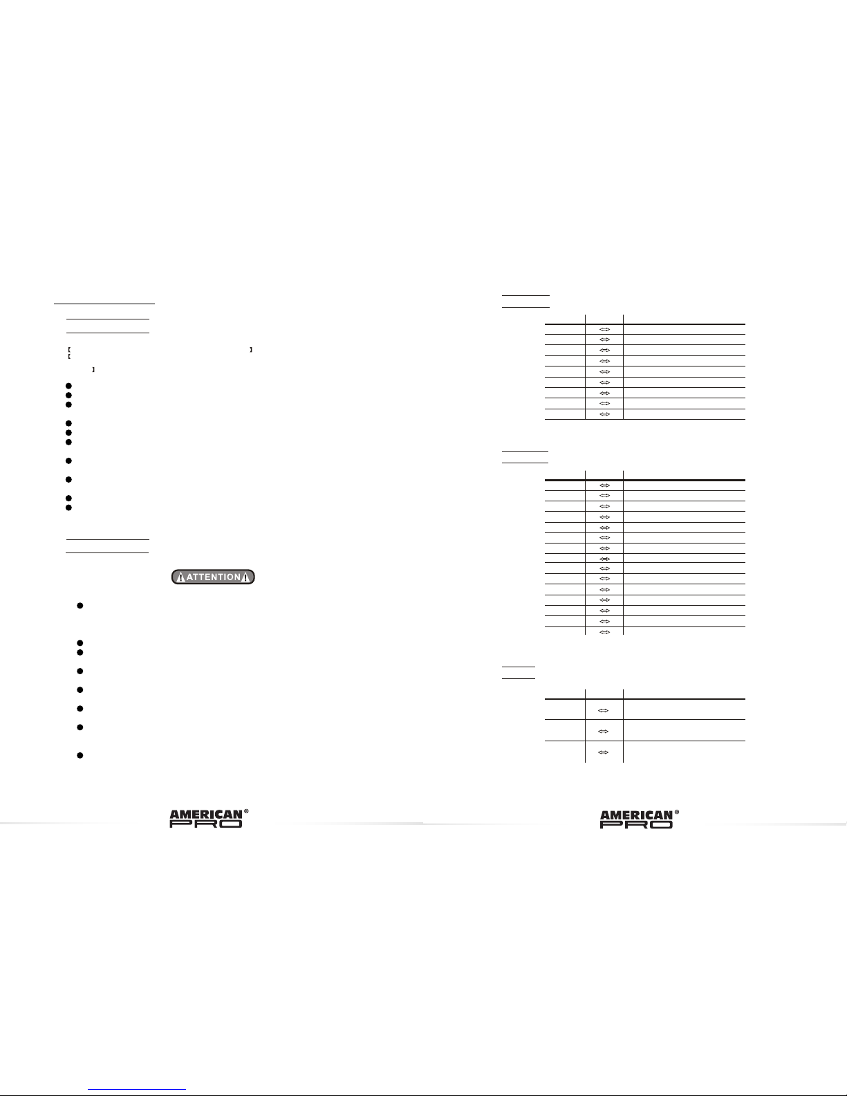
NEO Sion User manual

1
2
3
4
5
6
7
8
9
10 11 12
13
14
10
1
2
3
4
5
6
7
8
9
10
Cleart front plate
Completed lens set
LED PCB A
LED PCB B
Heat sink board
Power supply
Display PCB
Fan
Side cover
LED driver PCB
Fuse
Supporting bracket
No ITEM
Power output socket(white)
Power output socket(blue)
11
12
13
14
No ITEM
5.2MAINTENANCE
USER MANUAL
Please read the manual before installing and using ithis lighting device
Keep it for future reference
SION
www.neo-professional.com

ABLE OF CONTENTS
T
No display
1) Power connection error
2) Power supply error
3) Main PCB damaged
1) Check all power connections
2) Replace power supply
3) Replace main PCB
LED MODULE on,
but no control
from display
Main PCB amagedReplace Main PCB
LEDs of the same
color are not lit
1) LED PCB damaged1) Replace PCB board
LEDs of all colors
are not litMain PCB damagedReplace main PCB
Display normal,
but no respon
se to DMX512
controller
1) Signal connection error
2) DMX address error
1) Check all signal connections
2) Check DMX address setting
SITUATIONCAUSEPART ORDER NUMBER
ACTION
2) Main PCB damaged2) Replace Main PCB
3) Driver PCB damaged3) Replace Driver PCB
5.1TROUBLE SHOOTING
5APPENDIX
PART 1 PRODUCT (GENERAL)................................................................. 1.
1.1--PRODUCT INTRODUCTION........................................................................1.
1.2--PRODUCT FEATURES................................................................................1.
1.3--TECHNICAL SPECIFICATIONS................................................................... 2.
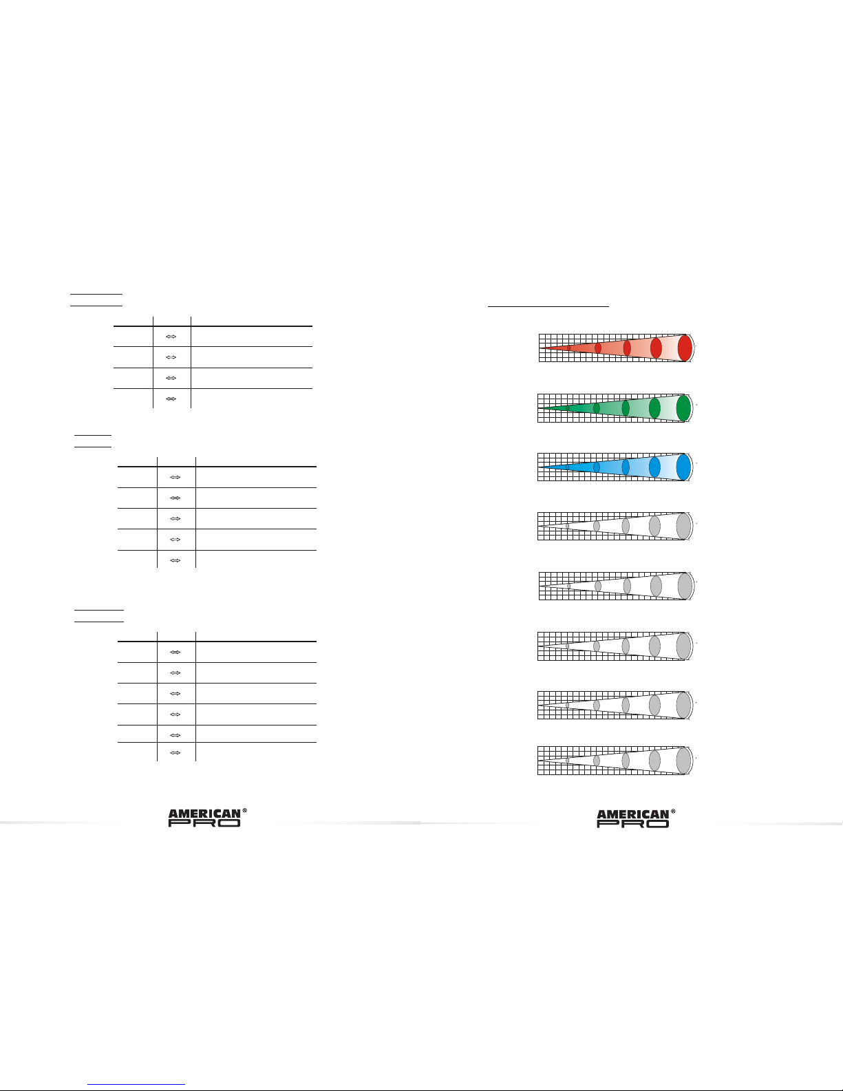
1.4--PHOTOMETRIC DATA.................................................................................3.
1.5--SAFETY WARNING.....................................................................................4.
PART 2 INSTALLATION ............................................................................5.
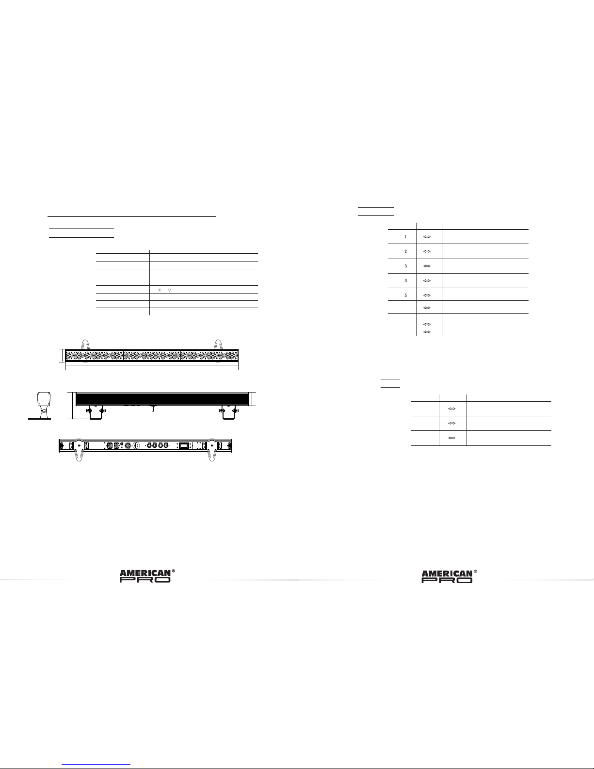
2.1--MOUNTING................................................................................................5.
2.2--POWER CONNECTION...............................................................................5.
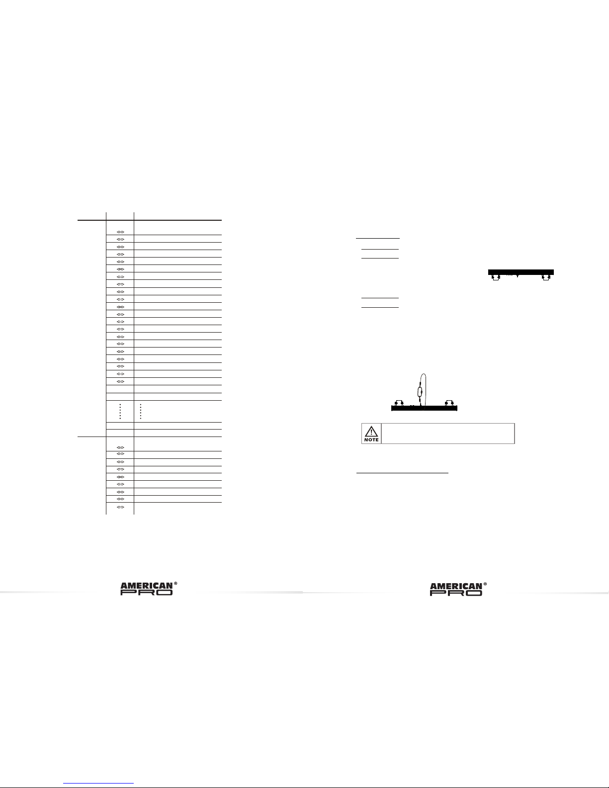
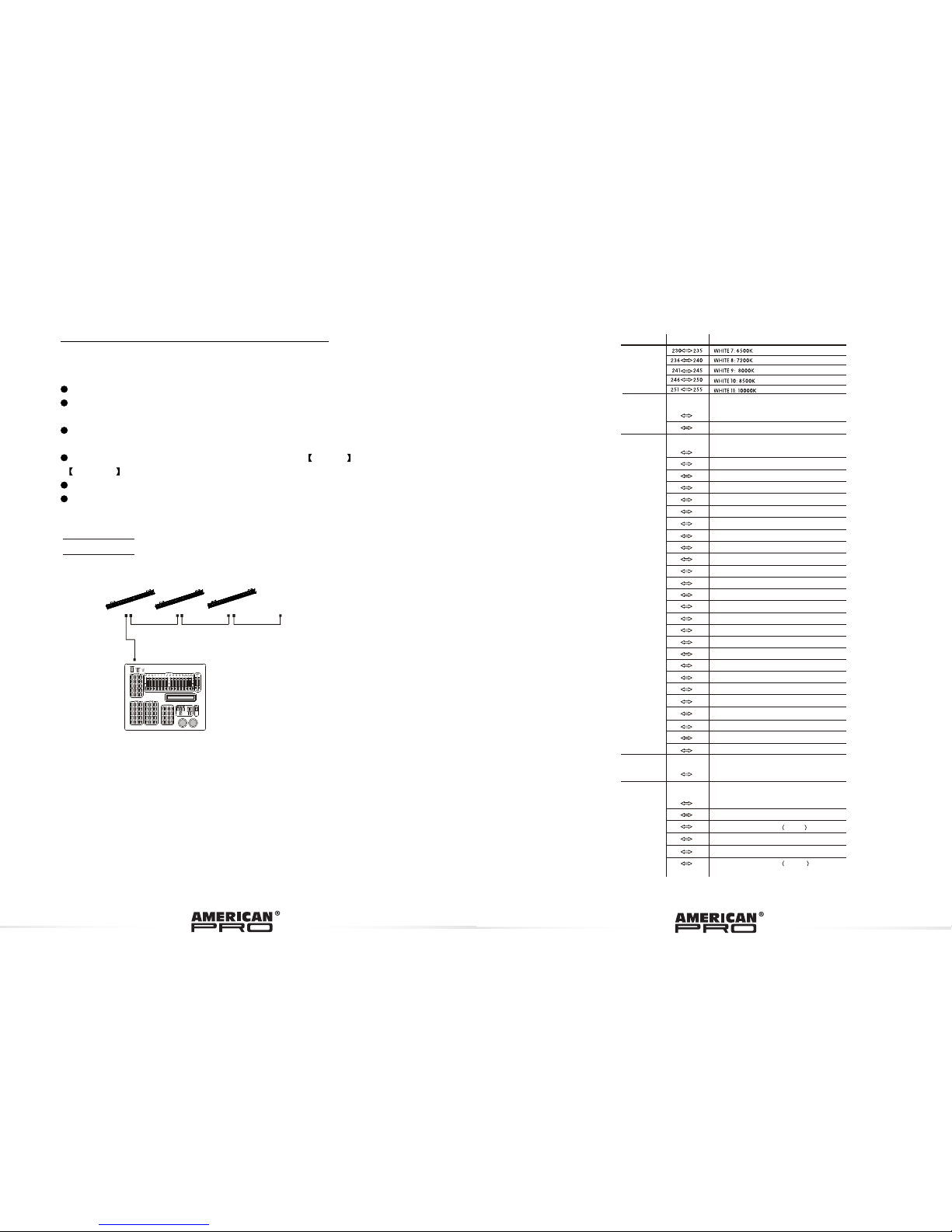
2.3--SETTING UP WITH A DMX512 CONTROLLER.............................................. 6.
2.3-1--DMX512 ADDRESSING WITHOUT ID ADDRESSING...........................................6.
2.3-2--DMX512 ADDRESSING WITH ID ADDRESS...........................................................7.
PART 3 DISPLAY PANEL OPERATION........................................................8.
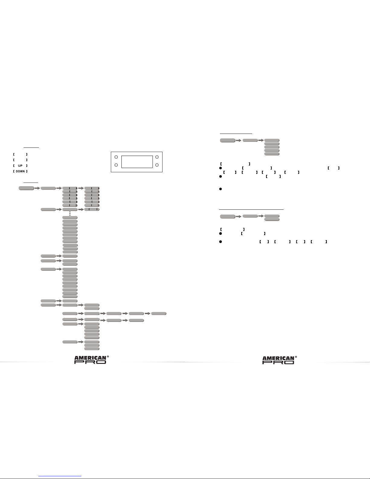
3.1--BASIC.........................................................................................................8.
3.2--MENU........................................................................................................ .8.
3.3--STATIC........................................................................................................9.
3.4--AUTO PLAYMODE......................................................................................10.
3.5--DMX ADDRESS.........................................................................................10.
3.6--RUN MODE................................................................................................10.
3.7--PERSONALITY..........................................................................................10.
3.8--ID ADDRESS..............................................................................................11.
3.9--SPECIAL SETTINGS..................................................................................11.
3.10--FACTORY DEFAULT SETTING...................................................................12.
3.11--EDIT CUSTOM.........................................................................................12.
3.12--WHITES SETTING..................................................................................12.
3.13--FAN SETTING..........................................................................................13.
3.14--ACTIVATE THE PASSWORD.....................................................................13.
.
PART 4 USING A DMX512 CONTROLLER...................................................14.
4.1--BASIC ADDRESSING................................................................................. 14.
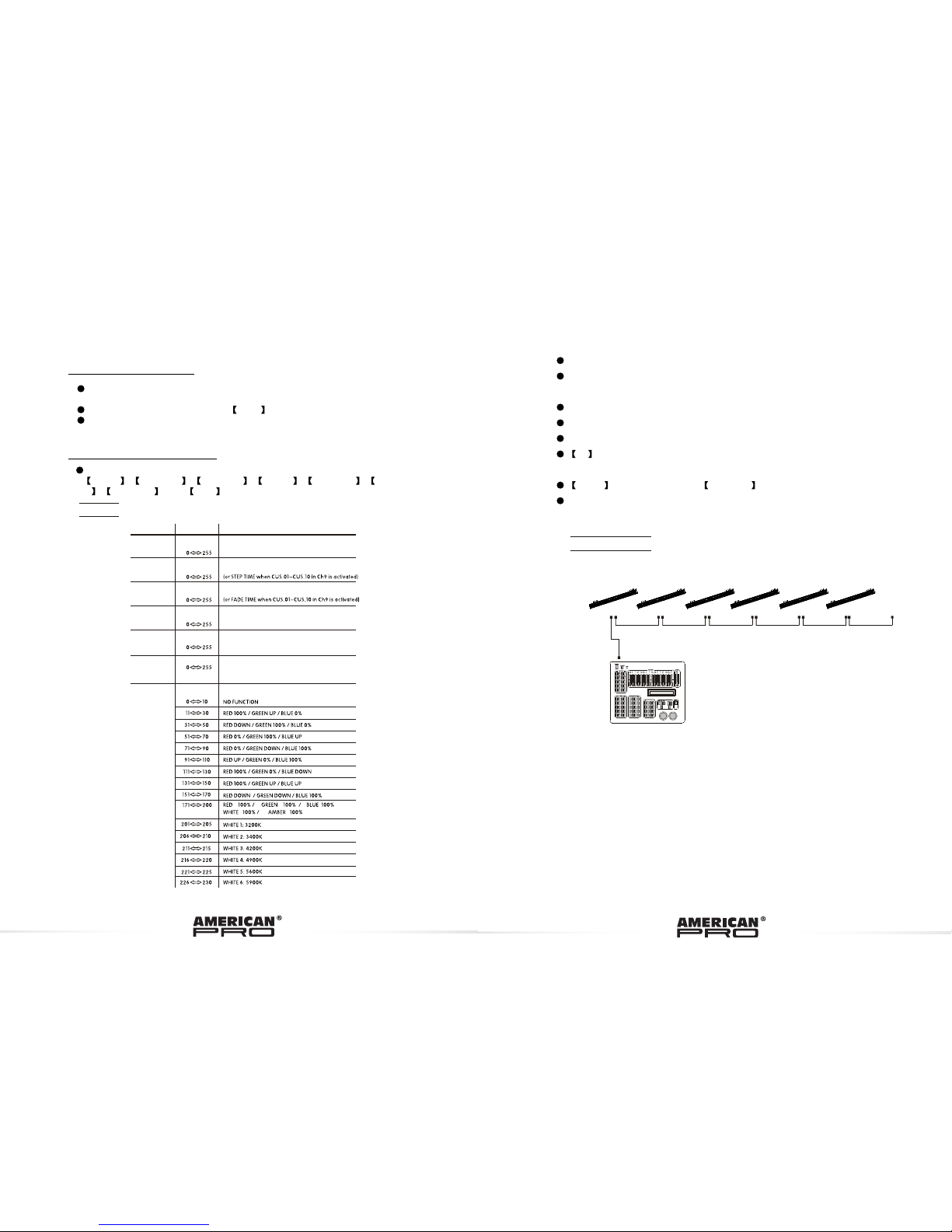
4.2--CHANNEL ASSIGNMENT............................................................................14.
4.3--BASIC INSTRUCTIONS FOR DMX512 OPERATION (TOUR) ........................ 20.
4.4--BASIC INSTRUCTIONS FOR DMX512 OPERATION (BLOCK 1 & 2)............... 20.
PART 5 APPENDIX....................................................................................21.
5.1--TROUBLE SHOOTING................................................................................21.
5.2--MAINTENANCE..........................................................................................22.

1.1PRODUCT INTRODUCTION
1.2PRODUCT FEATURES
LED FIXTURE
* RGBWA Dimmer 0-100%
* Strobe
* Automatic programs
* Custom programs
* LCD display
* Display control 'lock-out'
* Direct DMX512 input
* Independent ID address
* Lightweight aluminium casing
* Different white colors setting
This product is designed for indoor use. Suitable applications
include wash or effect lighting for stage, nightclub or touring
applications. Direct input of DMX512 signal allows the units to
be controlled from any DMX512 controller. This product can be
operated as a single unit or in multiple units for large applications.
1 PRODUCT (GENERAL)
4.3BASIC INSTRUCTIONS FOR DMX512
OPERATION (TOUR)
MASTER DIMMER
CH1 controls the intensity of the currently projected color
When the slider is at the highest position (255) the intensity of the output is the
maximum
RED, GREEN BLUE, WHITE & AMBER COLOR SELECTION
CH2, CH3 & Ch4, Ch5 & CH6 control the intensity ratio of each of the RED,
GREEN, BLUE, WHITE & AMBER LEDs.
When the slider is at the highest position (255) the intensity of the color is the
maximum.
CH2, CH3, Ch4 , Ch5 & CH6can be combined together to create over 16
million colors.
COLOR MACROS AND WHITE BALANCE
CH7 selects the required COLOR MACRO and whites in different color temp.
Ch7 has priority over CH2, CH3, CH4, CH5 , Ch6 & CH9.
CH1 is used to control the intensity of the COLOR MACRO
STROBE
CH 8 controls the strobe of CH2 to CH7.
ID ADDRESS SELECTION
CH12 is used to select the target ID address.
Each independent DMX address may have upto 66 independent ID addresses.
An ID address of 0 will activate all ID address locations.
AUTO
CH9 selects the preset AUTO programsAUTO 1-AUTO10 or the custom
programs CUSTOM1-CUSTOM 10.
Ch9 has priority over Ch2, Ch3, Ch4 , Ch5 & Ch6..
BLOCK SELECTION
Ch13 channel allows the user to select from combinations of different
colors and LED blocks in a quick-and-easy action
4.4BASIC INSTRUCTIONS FOR DMX512
OPERATION (BLOCK 1 & 2)
BLOCK 1
All leds divided as 3 blocks, each block include 6 red leds, 6 green leds and 6
blue leds.
BLOCK2
All leds divided as 3 blocks, each block include 6 red leds, 6 green leds, 6 blue
leds, 3 white leds and 3 amber leds.

990mm
75mm
156mm
77mm
1.3TECHNICAL SPECIFICATIONS
LED MOD UL E
Dimensions
LED MODULE:
Voltage
Rated Power
18 x 1W RED/ 18 x 1W GREEN /
18 x 1W BLUE/9 x1W WHITE / 9 x AMBER
Weight
LED/Unit
Cooling
990 x 156 x75mm
6Kg
100~240V...50/60Hz
87W
Environment Temperature-20~40
Forced air convection
1
2
0 255
3
0 255
0 255
HSV
HUE
SATURATION
VALUE
CHANNEL VALUE FUNCTION
0 255
0 255
0 255
0 255 BLUE
ARC 2+S
M AST ER D I MM ER
RED
G REE N
VALUE FUNCTION
0 255 WHI TE
60 255 AM BE R
70 9 NO F UNC T IO N
1 ~ 2 0 Hz
10 255
STRO BE
CHANNEL

1.4 PHOTOMETRIC DATA
1
2
0 255
3
4
0 255
0 255
0 255 BLUE
ARC 2+D
MASTER DIMMER
RED
GREEN
VALUE FUNCTION
50 255 WHITE
60 255 AMBER
CHANNEL
1
2
0 255
3
4
0 255
0 255
0 255 BLUE
MASTER DIMMER
RED
GREEN
VALUE FUNCTION
CHANNEL
ARC 1+D
1
2
0 255
3
4
0 255
0 255
0 255
BLUE
ARC 2
RED
GREEN
VALUE FUNCTION
50 255
WHITE
AMBER
CHANNEL
1
2
3
0
1
2
3
246 8 10Distance(m)
1316 329 146 82 53 LUX
1 5
R
1
2
3
0
1
2
3
246 8 10Distance(m)
600 150 67 38 24 LUX
A
1 5
1
2
3
0
1
2
3
246 8 10Distance(m)
3402 850 378 213 136 LUX
RGBW
1 5
1
2
3
0
1
2
3
246 8 10Distance(m)
350 87 40 22 14 LUX
B
1 5
1
2
3
0
1
2
3
246 8 10Distance(m)
3893 973 433 24 3 156LUX
RGBWA
1 5
1
2
3
0
1
2
3
246 8 10Distance(m)
566 142 63 35 23 LUX
W
1 5
RGB
1
2
3
0
1
2
3
246 8 10Distance(m)
2795 700 310 175 112 LUX
1 5
G
1
2
3
0
1
2
3
246 8 10Distance(m)
1300 325 145 81 52 LUX
1 5

1.5 SAFETY WARNING
IMPORTANT
ALWAYS READ THE USER MANUAL BEFORE OPERATION.
PLEASE CONFIRM THAT THE POWER SUPPLY STATED ON THE
PRODUCT IS THE SAME AS THE MAINS POWER SUPPLY IN YOUR
AREA.
This product must be installed by a qualified professional.
Always operate the equipment as described in the user manual.
A minimum distance of 0.5m must be maintained between the
equipment and combustible surface.
The product must always be placed in a well ventilated area.
Always make sure that the equipment is installed securely.
DO NOT stand close to the equipment and stare directly into the LED
light source.
Always disconnect the power supply before attempting and
maintenance.
Always make sure that the supporting structure is solid and can
support the combined weight of the products.
The earth wire must always be connected to the ground.
Do not touch the power cables if your hands are wet.
ATTENTION
This product left the place of manufacture in perfect condition. In
order to maintain this condition and for safe operation, the user must
always follow the instructions and safety warnings described in this
user manual.
Avoid shaking or strong impacts to any part of the equipment.
Make sure that all parts of the equipment are kept clean and free of
dust.
Always make sure that the power connections are connected correct
and secure.
If there is any malfunction of the equipment, contact your distributor
immediately.
When transferring the product, it is advisable to use the original
packaging in which the product left the factory.
Shields, lenses or ultraviolet screens shall be changed if they have
become damaged to such an extent that their effectiveness is
impaired.
The lamp (LED) shall be changed if it has become damaged or
thermally deformed.
BLOCK1 RED
BLOCK1 GREEN
BLOCK1 BLUE
0255
0
0
255
255
0255
0255
0255
0255
0
0
255
255
1
2
3
4
5
6
7
8
9
BLOCK1
14
15
0255
0
0
255
255
0255
0255
0255
0255
0
0
255
255
0255
0255
1
2
3
6
7
8
11
12
13
BLOCK2
0255
0255
4
5
0255
0255
9
10
ARC 1
VALUE FUNCTION
CHANNEL
BLOCK2 RED
BLOCK2 GREEN
BLOCK2 BLUE
BLOCK3 RED
BLOCK3 GREEN
BLOCK3 BLUE
BLOCK1 RED
BLOCK1 GREEN
BLOCK1 BLUE
BLOCK1 WHITE
BLOCK1 AMBER
BLOCK2 RED
BLOCK2 GREEN
BLOCK2 BLUE
BLOCK2 WHITE
BLOCK2 AMBER
BLOCK3 RED
BLOCK3 GREEN
BLOCK3 BLUE
BLOCK3 WHITE
BLOCK3 AMBER
1
3
4
0 255
0 255
0 255 BLUE
RED
GREEN
VALUE FUNCTION
CHANNEL
VALUE FUNCTION
CHANNEL

2.1MOUNTING
UPRIGHT
The LED MODULE can be
mounted in an upright or sitting
position using the supporting
brackets.
@ 220V: 12 units may be connected in series
@120V: 6 units may be connected in series
The LED MODULE can be mounted at any angle . It is possible to
further adjust the angle of the LED MODULEusing the
adjustment knobs located on the side of the fixture.
2.2POWER CONNECTIONS
HANGING
The LED MODULE can be mounted in a hanging position using
the support frame. It is possible to use any bolt of the correct
size and strength to mount the fixture. It is recommended to
use at least 2 mounting points per fixture. Mounting with a
clamp or other mounting bracket is recommended depending
on the requirements of your application.
For overhead use, always install two secure-chains that can
hold at least 10 times the weight of the fixture.
2 INSTALLATION
Note:If over 30 units to be connected, then a DMX signal amplifier
is needed.
12
ID ADDRESS
ID1~ID66
ID1
ID2
ID3
ID4
ID5
ID6
ID7
ID8
ID9
ID10
ID11
ID12
ID13
ID14
09
10 19
20 29
30 39
40 49
50 59
60 69
70 79
80 89
90 99
100 109
110 119
120 129
130 139
140 149
ID19
ID20
190 199
200 209
ID21
ID22
210
211
ID65
ID66
254
255
ID15
ID16
ID17
150 159
160 169
170 179
ID18180 189
13
BLOCK SELECTIONS
BLOCK1, BLOCK2, BLOCK3
0 4
5 34
35 64
65 94
95 124
125 154
155 184
215 255
BLOCK1
BLOCK2
BLOCK3
BLOCK1, BLOCK2
BLOCK2, BLOCK3
BLOCK1, BLOCK3
185 241 BLOCK1, BLOCK2, BLOCK3
NO FUNCTION
VALUE FUNCTION
CHANNEL

2.3SETTING UP WITH A DMX512 CONTROLLER
2.3-1DMX512 ADDRESSING WITHOUT ID ADDRESSING
(TOUR MODE)
The figure above shows a simple DMX512
layout with the starting address of the first
unit set at 1, with the second set at 13 and
so on... (Note that when used in this way,
the Ch12 ID function must be inactive
(CH13=0))
DMX512
CONTROLLER
Connect the DMX512 controller to the units in series.
Each unit has 13 DMX channels so the DMX Addresses should increase by
increments of 13 (e.g. 1,14,,27...)
The ID address has not been set so therefore when using the controller CH12
must be inactive ( CH12=0 ).
It is also possible to deactivate ID address selectingID OFFfrom the
Settingsmenu. on the fixture
Each DMX Address may be used as many times as required.
Any DMX address in the range from 001 to 512 may be used.
Example:
............
DMX Addr.1DMX Addr.14DMX Addr.27
0 255
AUTO SPEED
10
AUTO SPEED FOR Auto1~Auto10
Auto 6
Auto 7
Auto 8
Auto 9
111 120
Auto 10
121 130
131 140
141 150
151 160
161 170
Custom 2
Custom 1
171 180
181 190
191 200
201 210
211 220
09
10 29
30 69
70 129
Custom 3
Custom 4
Custom 5
Custom 6
0 10
11 20
21 30
31 40
41 50
9
61 70
81 90
91 100
101 110
Auto 1
Auto 2
Auto 3
Auto 4
Auto 5
71 80
51 60
80 9
10 255
11
130 189
190 255
221 230 Custom 7
231 240 Custom 8
241 250 Custom 9
251 255 Custom 10
1~20Hz
NO FUNCTION
STROBE
FANS OFF (STAY 3 SECONDS)
FANS LOW (STAY 3 SECONDS)
FANS NORMAL (STAY 3 SECONDS)
FANS HIGH (STAY 3 SECONDS)
FANS AUTO(STAY3 SECONDS)
AUTO + CUSTOM PROGRAMS+ FAN CONTROL
NO FUNCTION
DIMMER SPEED
LINEAR DIMMER
NON LINEAR DIMMER 1 fastest
NON LINEAR DIMMER 2
NON LINEAR DIMMER 3
NON LINEAR DIMMER 4 slowest
PRESET DIMMER SPEED FROMDISPLAY MENU
7
VALUE FUNCTION
CHANNEL

2.3-2DMX512 ADDRESSING WITH ID ADDRESS (TOUR MODE)
Connect the DMX512 controller to the units in series
Each unit has 10 DMX channels so the DMX Addresses should increase by
increments of 13 (e.g. 1,14,27...)
Each DMX Address may be used as many times as required.
Any DMX address in the range from 001 to 512 may be used.
Each DMX address may carry up to 66 separate ID addresses.
ID should be set in the menu on each unit in ascending values
(i.e. 1,2,3...)
ID On should be set in theSettingsmenu on each unit.
ID addresses are accessible from Ch12 on the DMX512 controller.
TOUR
Note: This product have three DMX512 channel configuration:
TOUR , BLOCK1 , , ARC 1 , ARC 1+D ,
2 , 2 andHSV
BLOCK2ARC
ARC +D
4.1 BASIC ADDRESSING
Connect all of the units in series using standard DMX512 signal cable or
the IP65 rated cable provided.
Set the DMX512 address in theDMXmenu.
It is possible to have the same DMX address or independent
addresses for each fixture.
4.2 CHANNEL ASSIGNMENT
4USING A DMX512 CONTROLLER
1
2
3
4
C O LO R M AC RO + W HITE B A LA NC E
5
6
BLUE
M AST ER D I MM ER
R ED
G R E EN
VALUE FUNCTION
WHI TE
AM BE R
CHANNEL
Example:
DMX Addr.1
ID Addr.1
DMX Addr.1
ID Addr.2
DMX Addr.1
ID Addr.3
DMX Addr.14
ID Addr.1
DMX Addr.14
ID Addr.2
DMX Addr.14
ID Addr.3
DMX512
CONTROLLER The figure above shows a simple DMX layout
which has used three units at each DMX address.
The three units have different ID addresses which
allows the user to collectively control the whole
group of units at that DMX address by setting
CH12 to 0, or to control each unit independently by
first selecting the DMX address and then by using
Ch12 to locate the target ID address.
............
7

UP
ENTER DOWN
MENU
3.2 MENU
RUN
PERSON
SLAVE
DMX
ADDERSS
TOUR
BLOCK1
BLOCK2
ARC 1
ID
1~66
1~512
ARC 1+D
ARC 2
STATIC
GREN 0~255
RED 0~255
BLUE 0~255
WHIT 0~255
AMBE 0~255
STRB 0~020
ARC 2+D
ARC 2+S
GREN 0~255
RED 0~255
BLUE 0~255
WHIT 0~255
AMBE 0~255
STRB 0~020
SETTINGS
UPLOAD
PASSWORD
RESET
PASSWORD
ID ONOFF
OFF
ON
**** SEND... END
**** RESET...
DIMMER
DIM1
OFF
DIM3
DIM2
DIM4
COLOR
RGB TO W
OFF
UC
HSV
MENU
enter the currently selected menu or confirm the current function value
scroll 'UP' through the menu list or increase the value of the current function
scroll 'DOWN' through the menu list or decrease the value of the current function
scroll through the main menu or return to the main menu
MENU
ENTER
3.1BASIC
3DISPLAY PANEL OPERATION3.13FAN SETTING
FAN SETTING
Enter the FAN SETTINGto select the fan speed modeOFF,
LOW,NORM,HIGHor AUTO.
When fan setting is on AUTOmode, the fixture will automatic adjust the
fan speed and fixture power, ensure the fixture temperature is not exceed
the limit.
When fan setting is on other modes, the fan will run according to the set
speed.
.
KEY-LOCK
Enter theKEY-LOCKmode to select whether the access password is on
or off.
Access password is UP +DOWN+UP +DOWN.
3.14ACTIVATE THE PASSWORD
FANS OFF
LOW
NORMAL
HIGH
AUTO
MENU
KEYLOCK
OFF
ON
MENU
AUTO AUTO 01
AUTO 10
CUSTOM 01
CUSTOM 02
CUSTOM 03
CUSTOM 04
CUSTOM 05
CUSTOM 06
CUSTOM 07
CUSTOM 08
CUSTOM 09
CUSTOM 10
SP 0~255

EDIT CUSTOM 01
CUSTOM 02
CUSTOM 03
CUSTOM 04
CUSTOM 05
CUSTOM 06
CUSTOM 07
CUSTOM 08
CUSTOM 09
CUSTOM 10
SCENE 01
SCENE 02
SCENE 03
SCENE 04
SCENE 05
SCENE 30
GREN 0~255
RED 0~255
BLUE 0~255
STRB 0~020
TIME 0~255
FADE 0~031
WHIT 0~255
AMBER 0~255
WHITE1
WHITE2
WHITE3
WHITE4
WHITE5
WHITE6
WHITE7
WHITE8
WHITE9
WHITE10
WHITE11
RGB TO W
GREN 0~255
RED 0~255
BLUE 0~255
CALIB
FANS OFF
LOW
NORMAL
HIGH
AUTO
KEYLOCK
OFF
ON
3.3 STATIC
STATIC COLOUR
Combine Red ,Green ,Blue , White and Amber to create
an infinite range of colors (0-255)
Set the value of the Strobe (0-20Hz)
EDIT CUSTOM 01
CUSTOM 02
CUSTOM 03
CUSTOM 04
CUSTOM 05
CUSTOM 06
CUSTOM 07
CUSTOM 08
CUSTOM 09
CUSTOM 10
SCENE 01
SCENE 02
SCENE 03
SCENE 04
SCENE 05
SCENE 30
GREN 0~255
RED 0~255
BLUE 0~255
STRB 0~020
TIME 0~255
FADE 0~031
WHIT 0~255
AMBER 0~255
MENU
3.11 EDIT CUSTOM
3.10 FACTORY DEFAULT SETTING
2
3
4
5
7
8
9
DMX address = 001
ID ON/OFF = ON
COLOR = OFF
KEYLOCK = OFF
Parsonaliey = TOUR
Run mode = DMX
10 Fan = Auto
1STATIC =000
ID address = 001
6
DIMMER = DIM4
EDIT = 000
11
WHITE1
WHITE2
WHITE3
WHITE4
WHITE5
WHITE6
WHITE7
WHITE8
WHITE9
WHITE10
WHITE11
RGB TO W
GREN 0~255
RED 0~255
BLUE 0~255
CALIB
MENU
3.12 WHITES SETTING
EDIT CUSTOM
Enter theEDIT CUSTOMmode to edit the custom programs
to
Each custom program has 30 steps that can be edited.
Each step allows the creation of a scene using RED RED, GREEN
GREEN, BLUE BLUE,WHITEWHITE, AMBERAMBER,
STROBE Stro., TIMETIMER& FADE FADE.
CUSTOM 1
CUSTOM 10 .
STATIC
GREN 0~255
RED 0~255
BLUE 0~255
WHIT 0~255
AMBE 0~255
STRB 0~020
GREN 0~255
RED 0~255
BLUE 0~255
WHIT 0~255
AMBE 0~255
STRB 0~020
MENU
WHITE 0~255
AMBER 0~255
WHITE 0~255
AMBER 0~255
GREN 0~255
RED 0~255
BLUE 0~255
GREN 0~255
RED 0~255
BLUE 0~255
WHITECALIB
Enter the WHITECALIBto select white color of different color temperature.
There are 11 pre-programmed White colors can be edited by usingRed,Green,
Blue , WhiteandAmber , andRGB TO WHITE by usingRed,Green
andBlue .

MENU
3.4 AUTO PLAY MODE
3.7 PERSONALITY
AUTO PLAY MODE
Select the targetAutoprogram .
ProgramsAUTO 01 to AUTO 10 are fully pre-programmed and will not be
altered by changes in EDIT CUSTOMmode. The auto speed can be set from
SP 1~255 .
Programs CUSTOM 01 to CUSTOM10are fully pre-programmed and can
be edited in EDIT CUSTOMmode.
3.5DMX ADDRESS
DMX ADDRESS
Enter theDMX ADDRESSmode to set the DMX ADDRESS.
RUNMODE
Enter theRUNMODEmode to set working mode.
DMXmode is for using the DMX512 controller to control the fixtures.
SLAVEmode is for Master -- Slave operation, or controlled fixture by
Pix-controller.
Note:When fixtures are under Auto program operation, theRUN MODEdoes
no works.
3.6RUN MODE
PERSONALITY
Enter thePERSONALITYmode to select DMX mode:,
, , , , , ,
or .
3.8 ID ADDRESS
3.9 SPECIAL SETTINGS
SETTINGS
UPLOAD
PASSWORD
RESET
PASSWORD
ID ONOFF
OFF
ON
**** SEND... END
**** RESET...
DIMMER
DIM1
OFF
DIM3
DIM2
DIM4
COLOR
RGB TO W
OFF
UC
MENU
ID ADDRESS
Enter theID ADDRESSmode to set the ID ADDRESS.
SETTING
EnterID in order to allow/disallow ID address function from the DMX512
controller.
SelectUPLDto upload the custom programs from the current MASTER unit to
the SLAVE units.
In order to activate the upload function the password must be entered.
Password is the same as the main access password.
When uploading the MASTER and SLAVE units will display YELLOW.
If an error occurs when uploading the MASTER and/or SLAVE units will display RED.
On successful uploading of the custom programs the MASTER and SLAVE units
will display GREEN.
In order to reset custom modes to default values select REST.
Enter Dimto select dimmer mode and dimmer speed. When DIMMER is
set to Off, then RGBW and MASTER DIMMER are linear. The Dim 1/2/3/4
are speed modes of the non linear dimmer , Dim1is the faster, while
Dim4is the slowest.
The factory default setting is Dim4 .
COLORis for activate/unactivate the color calibration functions.
When RGBWis selected, on RGB = 255,255,255, the color is displayed as
calibrated in CAL2 -- RGBW. WhenCOLORis set OFF, on RGB = 255,255,
255, the RGB values are not adjusted and the output is most powerful.
When [UC] is selected, the RGB output are adjusted to a standard preset universal color
which balances fixtures from different generations..
ADDERSS
1~512
MENU
RUN
SLAVE
DMX
MENU
PERSON TOUR
BLOCK1
BLOCK2
ARC 1
ARC 1+D
ARC 2
ARC 2+D
ARC 2+S
HSV
MENU
ID
1~66
MENU
AUTO AUTO 01
AUTO 10
CUSTOM 01
CUSTOM 02
CUSTOM 03
CUSTOM 04
CUSTOM 05
CUSTOM 06
CUSTOM 07
CUSTOM 08
CUSTOM 09
CUSTOM 10
SP 0~255
Table of contents
Other NEO Dj Equipment manuals

NEO
NEO NEO FLEX TRUSS User manual

NEO
NEO FOLLOWER 35ST User manual

NEO
NEO Blinder 64 User manual

NEO
NEO PROTON IP 12 QA User manual

NEO
NEO PROTON 12 USB User manual

NEO
NEO NEO STRIP GOLD User manual

NEO
NEO ION 715Z User manual

NEO
NEO ION 610B RGBW User manual

NEO
NEO Mini Panel User manual

NEO
NEO PROTON IP QW ZOOM User manual

NEO
NEO ELIPSOLED 3100 MAX User manual

NEO
NEO FRESNELED COLOR User manual

NEO
NEO ELIPSOLED 5600 MAX Torch 4000 User manual

NEO
NEO Proton 12 HEX USB User manual

NEO
NEO PROTON IP User manual

NEO
NEO ION 740Z User manual

NEO
NEO FOLLOWER 15R User manual

NEO
NEO Proton 6 QUAD USB User manual

NEO
NEO ZOOM PANEL User manual

NEO
NEO ION 1915Z User manual