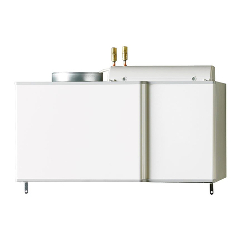
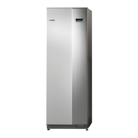
Nibe VVM S320 User guide

Installer manual
Indoor module
NIBE VVM S320
IHB EN 2327-1
631794

Quick guide
NAVIGATION
Browse
ScrollSelect The dots at the bottom
edge show that there
are more pages.
If the menu has several
sub-menus, you can
see more information
by dragging up or down
with your finger.
Most options and func-
tions are activated by
lightly pressing on the
display with your finger.
Drag to the right or left
with your finger to
browse between the
pages.
Setting the indoor temperature.
13.45 3 October
Climate system 1
Offset
Heating
Smartguide
Hi!
Your system is working properly. Do you want help making
changes?
Yes please, take me to Smartguide.
October13.45 3
Here, you can set the temperature in the installation's zones.Smartguide helps you both to view information about the current
status and to make the most common settings easily. The inform-
ation that you see depends on the product you have and the ac-
cessories that are connected to the product.
Product overview
Company AB
Phone number
VVMS320
01234567890123
1.0.0
Product
overview
Product name
Serial number
Software
Service
October13.45 3
Update
Increasing hot water temperature
13.45 3 October
More hot water
Hot water
Here, you can find information about product name, the product's
serial number, the version of the software and service. When there
is new software to download, you can do it here (provided that
VVM S320 is connected to myUplink).
Here, you can start or stop a temporary increase in the hot water
temperature.

41 Important information
4Safety information
4Symbols
4Marking
4Serial number
5Inspection of the installation
6Compatible outdoor modules
72 Delivery and handling
7Transport
7Assembly
8Supplied components
9Handling panels
113 Indoor module's design
11General
13Distribution boxes
144 Pipe connections
14General
16Dimensions and pipe connections
16Connecting to air/water heat pump
17Use without heat pump
17Climate system
17Cold and hot water
17Installation alternative
195 Electrical connections
19General
21Connections
27Settings
296 Commissioning and adjusting
29Preparations
29Filling and venting
30Start-up and inspection
31Setting the cooling/heating curve
337 myUplink
33Specification
33Connection
33Range of services
348 Control - Introduction
34Display unit
35Navigation
35Menu types
37Climate systems and zones
389 Control – Menus
38Menu 1 – Indoor climate
42Menu 2 – Hot water
44Menu 3 - Info
45Menu 4 - My system
49Menu 5 - Connection
50Menu 6 - Scheduling
51Menu 7 - Service
5810 Service
58Service actions
6111 Disturbances in comfort
61Info-menu
61Manage alarm
61Troubleshooting
6312 Accessories
6513 Technical data
65Dimensions
66Technical specifications
67Electrical circuit diagram
79Item register
83Contact information
3Table of ContentsNIBE VVM S320
Table of Contents

Safety information
This manual describes installation and service procedures
for implementation by specialists.
The manual must be left with the customer.
For the latest version of the product’s documentation, see
nibe.eu.
NOTE
Also read the enclosed Safety Manual before
starting the installation.
Symbols
Explanation of symbols that may be present in this manual.
NOTE
This symbol indicates danger to person or machine.
Caution
This symbol indicates important information about
what you should consider when installing or servi-
cing the installation.
TIP
This symbol indicates tips on how to facilitate us-
ing the product.
Marking
Explanation of symbols that may be present on the product’s
label(s).
Dangerous voltage.
Danger to person or machine.
!
Read the User Manual.
Disconnect the voltage supply before starting work.
Serial number
The serial number can be found at the bottom right on
VVM S320, in the display on the home screen "Product
overview" and on the type plate (PZ1).
Caution
You need the product's (14 digit) serial number for
servicing and support.
NIBE VVM S320Chapter 1 | Important information4
Important information

Inspection of the installation
Current regulations require the heating installation to be inspected before it is commissioned. The inspection must be
carried out by a suitably qualified person. Fill in the page for information about installation data in the User manual.
DateSignatureNotesDescription
✔
Connecting to air/water heat pump
System flushed
System vented
Particle filter
Safety valve
Shut off valves
System pressure
Connected according to outline diagram
Flows according to table in section "Minimum
system flows", chapter "Pipe connections"
Cold and hot water
Shut off valves
Mixing valve
Safety valve
Electrical connections
Connected communication
Circuit fuses
Fuses property
Outside sensor
Room sensor
Current sensor
Safety breaker
Earth circuit-breaker
Setting emergency mode
Miscellaneous
Docked to
5Chapter 1 | Important informationNIBE VVM S320

Compatible outdoor modules
F2040
F2040-12
Part no. 064 092
F2050
F2050-10
Part no. 064 318
F2050-6
Part no. 064 328
F2120
F2120-16 3x400 V
Part no. 064 139
S2125
S2125-8 3x400 V
Part no. 064 219
S2125-8 1x230 V
Part no. 064 220
S2125-12 3x400 V
Part no. 064 217
S2125-12 1x230 V
Part no. 064 218
NIBE SPLIT HBS 05
HBS 05-12
Part no. 067 480
AMS 10-12
Part no. 064 110
NIBE SPLIT HBS 20
HBS 20-6
Part no. 067 668
AMS 20-6
Part no. 064 235
HBS 20-10
Part no. 067 819
AMS 20-10
Part no. 064 319
NIBE VVM S320Chapter 1 | Important information6

Transport
VVM S320 should be transported and stored vertically in a
dry place.
However, the VVM S320 can be carefully laid on its back
when being moved into the building.
R
0
R
0
Assembly
•Position VVM S320 on a solid foundation indoors that
withstands water and the weight of the product.
•Use the product’s adjustable feet to attain a horizontal
and stable set-up.
30 - 50 mm
30 - 50 mm
15 - 40 mm
20-55 mm
•The space where VVM S320 is located must be frost-free.
•Since water comes from VVM S320, the area where
VVM S320 is located must be equipped with floor drainage.
INSTALLATION AREA
Leave a free space of 800 mm in front of the product. All
service on VVM S320 can be carried out from the front.
50 50
10 – 25
800
NOTE
Leave 10 – 25 mm free space between VVM S320
and the wall behind for routing cables and pipes.
7Chapter 2 | Delivery and handlingNIBE VVM S320
Delivery and handling

Supplied components
Room sensor(BT50)
1 x
Outdoor temperature sensor
(BT1)
1 x
UN
Compression ring coupling2
1 x
LEK
LEK
LEK
Current sensor1
3 x
Label for external control
voltage for the control sys-
tem
1 x
1Only VVM S320 3x400 V.
2Only applies to Germany, Austria, Switzerland and Italy. This
compression ring coupling must be used instead of the factory-
fitted plug, if you want to connect hot water circulation to XL5.
LOCATION
The kit of enclosed items is placed on top of the indoor
module.
NIBE VVM S320Chapter 2 | Delivery and handling8

Handling panels
OPEN FRONT HATCH
Press the hatch's top left corner to open it.
REMOVE THE FRONT
1. Remove the screw in the hole next to the on/off button
(SF1).
2. Pull the panel's top edge towards you and lift diagonally
upwards to remove it from the frame.
UN
ASSEMBLE THE FRONT
1. Hook one bottom corner of the front onto the frame.
2. Hook the other corner in place.
3. Check the display is straight. Adjust if necessary.
9Chapter 2 | Delivery and handlingNIBE VVM S320

4. Press the top of the front section against the frame and
screw it into place.
OPEN VENT COVER
REMOVE SIDE PANEL
The side panels can be removed to facilitate the installation.
1. Remove the screws from the upper and lower edges.
UN
2. Twist the panel slightly outwards.
UN
3. Move the panel outwards and backwards.
UN
4. Assembly takes place in the reverse order.
NIBE VVM S320Chapter 2 | Delivery and handling10

General
UN
BP5
BT63
GP1
CM1
XL4 XL3 XL9 PZ1
PZ3
XL8 X L1 XL2
FL1
FL2
QN10 BT7
AA4
SF1
XF3
UN
UB1
UB2
FC1
XL5
QM20
QM22
BT3
BT2
XF8
BF1
BT6
VM1
QM11
QM13
RM1
EB1
BT5
GP6
11Chapter 3 | Indoor module's designNIBE VVM S320
Indoor module's design

Pipe connections
Heating medium connection, supplyXL1
Heating medium connection, returnXL2
Cold water connectionXL3
Hot water connectionXL4
Hot water circulation connection 1
XL5
Docking connection, supply, from heat pumpXL8
Docking connection, return, to heat pumpXL9
1Not included in VVM S320 CU
HVAC components
Closed expansion vesselCM1
Safety valve, hot water heater1
FL1
Safety valve, heating mediumFL2
Circulation pumpGP1
Circ. pump 2GP6
Filler valve, heating mediumQM11
Filler valve, heating mediumQM13
Venting valve, climate systemQM20
Venting valve, coilQM22
Reversing valve, heating/hot waterQN10
Non-return valve, cold water2
RM1
Overflow cupWM1
1Not included in VVM S320 R 3x400 V NL.
2Not included in VVM S320 R 3x400 V NL, VVM S320 E 3x400 V DK or VVM
S320 R EM 3x230 V.
Sensors etc.
Flow meterBF1
Pressure gauge, heating mediumBP5
Flow line sensorBT2
Return line sensorBT3
Controlling hot water sensorBT5
Controlling hot water sensorBT6
Display hot water sensorBT7
Supply temperature sensor after additional heatBT63
Electrical components
Display unitAA4
Immersion heaterEB1
Miniature circuit breaker1
FC1
On/off buttonSF1
USB socketXF3
Network connection for myUplinkXF8
1Only VVM S320 1x230 V./3x230 V.
Miscellaneous
Rating platePZ1
Serial numberPZ3
Cable glandUB1–UB2
Designations according to standard EN 81346-2.
NIBE VVM S320Chapter 3 | Indoor module's design12

Distribution boxes
-X29
-X28
1 0-5V
2 +5V
3 AUX1
4 AUX2
5 AUX3
6 AUX4
7 AUX5
8 AUX6
9 AUX7
10 AUX8
11AUX9
12 BT25
1
1
2
3
2
3
4
5
6
7
8
9
10
11
12
GND
+12V
B
A
OT+
OT−
0-5V
PWM0
PWM1
CPU
EXT COM
INT COM
ERROR
POWER
+5V
GND
BE1
BE2
BE3
K10
-X27
NO
O
NC
AUX-RELAY
13 BT50
14 BT1
-X30
FQ10
AA2
FQ10-S2
AA8
ELECTRICAL COMPONENTS
Base cardAA2
Electrical anode board1
AA8
Temperature limiterFQ10
FQ10-S2 Reset button for temperature limiter
1Only VVM S320 with enamelled vessel.
13Chapter 3 | Indoor module's designNIBE VVM S320

General
Pipe installation must be carried out in accordance with
current norms and directives.
The system requires the dimensions of the radiator circuit
to be designed for a low temperature heating medium. At
the lowest dimensioned outdoor temperature (DOT), the
highest recommended temperatures are 55 °C on the supply
line and 45 °C on the return line, but VVM S320 can handle
up to 70 °C.
Caution
Ensure that incoming water is clean. When using
a private well, it may be necessary to supplement
with an extra water filter.
NOTE
Any high points in the climate system, must be
equipped with air vents.
NOTE
The pipe systems need to be flushed out before
the indoor module is connected so that any debris
cannot damage component parts.
NOTE
Water may drip from the safety valve. A factory-
fitted overflow pipe runs from the safety valve to
an overflow cup. An overflow pipe has to be routed
from the overflow cup to a suitable drain. The
overflow pipe must be inclined along its entire
length to prevent pockets where water can accu-
mulate, and must be frost-proof.
MINIMUM SYSTEM FLOWS
NOTE
An undersized climate system can result in dam-
age to the product and lead to malfunctions.
Each climate system must be dimensioned individually to
provide the recommended system flows.
The installation must be dimensioned to provide at least the
minimum defrosting flow at 100 % circulation pump opera-
tion.
Minimum re-
commended
pipe dimen-
sion (mm)
Minimum re-
commended
pipe dimen-
sion (DN)
Minimum flow
duringdefrost-
ing
100% circula-
tion pump op-
eration (l/s)
Air/waterheat
pump
22200.29AMS 10-12/
HBS 05-12
Minimum re-
commended
pipe dimen-
sion (mm)
Minimum re-
commended
pipe dimen-
sion (DN)
Minimum flow
duringdefrost-
ing
100% circula-
tion pump op-
eration (l/s)
Air/waterheat
pump
22200.19
AMS 20-
6/HBS 20-6
AMS 20-
10/HBS 20-10
Minimum re-
commended
pipe dimen-
sion (mm)
Minimum re-
commended
pipe dimen-
sion (DN)
Minimum flow
duringdefrost-
ing
100% circula-
tion pump op-
eration (l/s)
Air/waterheat
pump
22200.29F2040-12
Minimum re-
commended
pipe dimen-
sion (mm)
Minimum re-
commended
pipe dimen-
sion (DN)
Minimum flow
duringdefrost-
ing
100% circula-
tion pump op-
eration (l/s)
Air/waterheat
pump
22200.19
F2050-6
F2050-10
Minimum re-
commended
pipe dimen-
sion (mm)
Minimum re-
commended
pipe dimen-
sion (DN)
Minimum flow
duringdefrost-
ing
100% circula-
tion pump op-
eration (l/s)
Air/waterheat
pump
28250.38
F2120-16
(3x400 V)
Minimum re-
commended
pipe dimen-
sion (mm)
Minimum re-
commended
pipe dimen-
sion (DN)
Minimum flow
duringdefrost-
ing
100% circula-
tion pump op-
eration (l/s)
Air/waterheat
pump
28250.32
S2125-8
(1x230 V)
S2125-8
(3x400 V)
S2125-12
(1x230 V)
S2125-12
(3x400 V)
NIBE VVM S320Chapter 4 | Pipe connections14
Pipe connections

SYSTEM VOLUME
H
VVM S320 is equipped with an expan-
sion vessel (CM1).
The volume of the expansion vessel
is 10 litres and it is pre-pressurised as
standard to 0.5 bar. As a result, the
maximum permitted height "H"
between the expansion vessel and the
highest installed radiator is 5 m, see
figure.
If the pre-pressure is not high enough,
it can be increased by filling with air
via the valve in the expansion vessel. Any change in the pre-
pressure affects the ability of the expansion vessel to handle
the expansion of the water.
The maximum system volume, excluding VVM S320, is 220
litres at the above-mentioned pre-pressure.
SYMBOL KEY
MeaningSymbol
Shut-off valve
Tapping valve
Non-return valve
Mixing valve
Circulation pump
Immersion heater
Expansion vessel
Filterball
Safety valve
Trim valve
Reversing valve/shunt
Overflow valve
Domestic hot water
Outdoor module
Hot water circulation
Heating system
Heating system with lower temperature
SYSTEM DIAGRAM
VVM S320 consists of a water heater with charge coil, ex-
pansion vessel, immersion heater, circulation pumps, buffer
vessel and control system. VVM S320 connects to the cli-
mate system.
VVM S320 is intended for connection and communication
with a compatible NIBE outdoor unit, and together they
constitute a complete heating installation.
When it is cold outdoors, the outdoor unit works with the
indoor module, and if the outdoor air temperature falls below
the outdoor unit’s working range, all heating is performed
by the immersion heater.
XL 8 2
4 3 9 1
Connection, heating medium flow lineXL1
Connection, heating medium return lineXL2
Connection, cold waterXL3
Connection, hot waterXL4
Connection, docking from heat pumpXL8
Connection, docking to heat pumpXL9
Caution
This is a principle of operation. For more detailed
information about VVM S320, see section "Indoor
module's design".
15Chapter 4 | Pipe connectionsNIBE VVM S320

Dimensions and pipe
connections
622
600
560 440
70
1800
20-50
25
60
135
210
390
465
540
XL4 XL9 XL8XL3 XL1 XL2
560 440
70
1800
20-50
30
600
60
135
210
390
465
540
620
PIPE DIMENSIONS
Connection
22mmHeating medium supply/return ØXL1 / XL2
22mmCold/hot water ØXL3 / XL4
22mmDocking connection, supply (from heat
pump) / Docking connection, return (to
heat pump) Ø
XL8 / XL9
Connecting to air/water heat
pump
NIBE recommends installing VVM S320 as close to the heat
pump as possible to obtain the optimum comfort.
You can find a list of compatible air/water heat pumps in
section "Compatible outdoor modules".
Caution
Also, consult the Installer Manual for your air/water
heat pump.
Install as follows:
•pressure relief valve
Some heat pump models have a factory-fitted safety
valve.
•drain valve
For draining the heat pump during prolonged power fail-
ures. Only for heat pumps that do not have a gas separat-
or.
•non-return valve
A non-return valve is only required in those installations
where the placement of the products in relation to each
other can cause self-circulation.
If the heat pump is already fitted with a non-return valve,
there is no need to install another.
•shut-off valve
To facilitate any future servicing.
•filterball or particle filter
Installed before connection "heating medium return" (XL2)
(the lower connection) on the vacuum pump.
In installations with a particle filter, the filter is combined
with an additional shut-off valve.
EB101-XL1
EB101-XL2
XL8
XL9
NIBE VVM S320Chapter 4 | Pipe connections16

Use without heat pump
The indoor unit can be used without a heat pump, i.e solely
as an electric boiler, for example to produce heat and hot
water before the heat pump is installed.
To use the indoor unit as an electric boiler, you need:
1. connect the pipe for docking coming in from the heat
pump (XL8) with the pipe out to the heat pump (XL9)
2. To make software settings according to section "Com-
missioning without heat pump".
XL8
XL9
Climate system
A climate system is a system that regulates the indoor
temperature with the help of the control system in VVM S320
and, for example, radiators, underfloor heating, underfloor
cooling, fan coils, etc.
CONNECTING THE CLIMATE SYSTEM
Install as follows:
•When connecting to a system with thermostats, either a
bypass valve must be fitted or, alternatively, some of the
thermostats must be removed to ensure there is sufficient
flow and heat emission.
XL1
XL2
Cold and hot water
The settings for hot water are made in menu 7.1.1 - "Hot
water".
CONNECTING COLD AND HOT WATER
Install as follows:
•shut-off valve
•mixing valve
A mixer valve must also be installed, if the factory setting
for hot water is changed. National regulations must be
observed.
XL3
XL4
VVM S320 E 3X400 V DK AND VVM S320 R
3X230 V
Install as follows:
•shut-off valve
•non-return valve
•mixing valve
A mixer valve must also be installed, if the factory setting
for hot water is changed. National regulations must be
observed.
XL3
XL4
VVM S320 R 3X400 V NL
Install as follows:
•shut-off valve
•non-return valve
•pressure relief valve
The safety valve must have a maximum 1.0 MPa (10.0 bar)
opening pressure and be installed on the incoming domest-
ic water line as shown.
•mixing valve
A mixer valve must also be installed, if the factory setting
for hot water is changed. National regulations must be
observed.
XL3
XL4
Installation alternative
VVM S320 can be installed in several different ways, some
of which are shown here.
Further option information is available at nibe.eu and in the
respective assembly instructions for the accessories used.
See page 63 for a list of the accessories that can be used
with VVM S320.
17Chapter 4 | Pipe connectionsNIBE VVM S320

EXTRA CLIMATE SYSTEM
In buildings with several climate systems that require differ-
ent supply temperatures, the accessory ECS 40/ECS 41 can
be connected.
A shunt valve then lowers the temperature to the underfloor
heating system, for example.
-EP21-GP10-EP21-BT2
-EP21-AA25
-EP21-BT3
-EP21-QN25
-EP21
EXTRA HOT WATER HEATERS
The system should be supplemented with an extra water
heater, if a large bath tub or other significant consumer of
hot water is installed.
Water heater with immersion heater
In a water heater with an immersion heater, the water is
initially heated by the heat pump. The immersion heater in
the water heater is used for keeping warm and when the
heat pump does not have sufficient power.
The water heater’s flow is connected after VVM S320.
HOT WATER CIRCULATION
A circulation pump can be controlled by VVM S320 to circu-
late the hot water. The circulating water must have a tem-
perature that prevents bacterial growth and scalding, and
national standards must be satisfied.
The HWC return can be connected to XL5 or a freestanding
water heater. If an electric water heater is connected after
the heat pump, the HWC return must be connected to the
water heater.
The circulation pump is activated via the AUX output in menu
7.4 -"Selectable in/outputs".
HWC can be supplemented with a hot water sensor for HWC
(BT70) and (BT82), which is connected via the AUX input
and activated in menu 7.4 -"Selectable in/outputs".
-QZ1-FQ3
-QZ1-GP11
-QZ1-RM1
-QZ1-RN1
-QZ1
NIBE VVM S320Chapter 4 | Pipe connections18

General
All electrical equipment, except the outdoor sensors, room
sensors and the current sensors are ready connected at the
factory.
•Electrical installation and wiring must be carried out in
accordance with national provisions.
•Disconnect VVM S320 before insulation testing the house
wiring.
•If the building is equipped with an earth-fault breaker,
VVM S320 should be equipped with a separate one.
•VVM S320 must be installed via an isolator switch. The
cable area has to be dimensioned based on the fuse rating
used.
•If a miniature circuit breaker is used, this must have at
least triggering characteristic "C". See section "Technical
specifications" for fuse size.
•Use a screened cable for communication with the heat
pump.
•To prevent interference, communication cables to external
connections must not be laid in the vicinity of high voltage
cables.
•The minimum area of communication and sensor cables
to external connections must be 0.5 mm² up to 50 m, for
example EKKX, LiYY or equivalent.
•For an electrical wiring diagram for VVM S320, see the
"Technical specifications" section.
•When routing a cable into VVM S320, the cable grommets
(UB1) and (UB2) must be used.
•
UB1
UB2
FC1
NOTE
Electrical installation and any servicing must be
carried out under the supervision of a qualified
electrician. Disconnect the current using the cir-
cuit breaker before carrying out any servicing.
NOTE
If the supply cable is damaged, only NIBE, its ser-
vice representative or similar authorised person
may replace it to prevent any danger and damage.
NOTE
Check the connections, main voltage and phase
voltage before the machine is started to prevent
damage to the indoor module's electronics.
NOTE
Do not start the system before filling up with wa-
ter. Components in the system could be damaged.
MINIATURE CIRCUIT-BREAKER
The operating circuit in VVM S320 and some of its internal
components are fused internally by a miniature circuit
breaker (FC1).
Only VVM S320 1x230 V./3x230 V.
19Chapter 5 | Electrical connectionsNIBE VVM S320
Electrical connections

ACCESSIBILITY, ELECTRICAL CONNECTION
Removing the cover
The hatch is opened using a screwdriver.
Removing the covers
The cover is opened using a screwdriver.
CABLE LOCK
Use a suitable tool to release/lock cables in the indoor
module terminal blocks.
Terminal block
1.
2.
TEMPERATURE LIMITER
-X29
-X28
1 0-5V
2 +5V
3 AUX1
4 AUX2
5 AUX3
6 AUX4
7 AUX5
8 AUX6
9 AUX7
10AUX8
11AUX9
12 BT25
1
1
2
3
2
3
4
5
6
7
8
9
10
11
12
GND
+12V
B
A
OT+
OT−
0-5V
PWM0
PWM1
CPU
EXT COM
INT COM
ERROR
POWER
+5V
GND
BE1
BE2
BE3
K10
-X27
NO
O
NC
AUX-RELAY
13 BT50
14 BT1
-X30
FQ10-S2
The temperature limiter (FQ10) cuts the power supply to the
electric additional heat if the temperature rises above 89 °C
and it is reset manually.
Resetting
The temperature limiter (FQ10) is accessed behind the front
cover. Reset the temperature limiter by pressing its button
(FQ10-S2).
NIBE VVM S320Chapter 5 | Electrical connections20
Other manuals for VVM S320
4
Table of contents
Other Nibe Control Unit manuals
Popular Control Unit manuals by other brands

Alfalaval
Alfalaval 741 Series instruction manual

Festo
Festo ZSB-1/8-B operating instructions

Alpha ESS
Alpha ESS SMILE-BAT-10.3P installation manual

Kromschroeder
Kromschroeder VG 6-15/10 operating instructions

Delta
Delta Hikvision DS-2FP2020 user manual

Goldline
Goldline GL-235-LV Installation & operation manual