Nibe SCU 10 User manual

INSTALLATION AND MAINTENANCE INSTRUCTIONSMOS GB 1227-2
SCU 10
031966 SCU 10
LEK


For Home Owners
General
To be filled in when the product has been installed 2
System description
Principle of operation 3
Front panel
Display explanation 4
Settings
Main menu 5
Control 5
3 Menu Operation 5
4 Menu Operating times 5
5 Menu Temperatures 5
Control
System 6
Menus 8
For the Installer
General information for the installer
Docking 10
Inspection of the installation 10
Menu Settings
Set temp tank1 11
dTStart tank1 11
dTStop tank1 11
Min speed pump 11
Extra heating 11
Extra cooling 11
Difference control Function (Diff. controls) 12
Protection functions 12
Service 12
Manual test 13
Extra 13
Vacuum pipe 14
Protection functions 14
Flow meter 15
Factory setting 15
Reset operating time 16
Time graph temp 16
Time graph operation 16
Sensor calibration 16
Prioritised Tank 17
Miscellaneous
Control
System 18
Menus 20
Dealing with malfunctions
Troubleshooting 22
Components
Component positions 23
List of components 23
Dimensions
Dimensions SCU 10 24
Electrical circuit diagram
Technical specifications
Enclosed kit
Temperature sensor 27
1SCU 10
Table of Contents

General
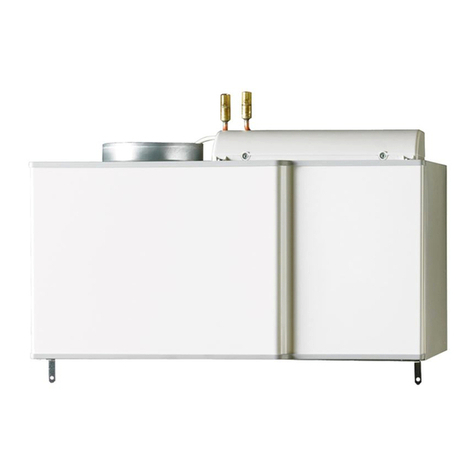
NIBE SCU 10 is a control module designed to optimally control solar heating together with other heating equipment.
Rights to make any design modifications are reserved.
To be filled in when the product has been installed
The serial number, must always be stated in all correspondence with NIBE.
______________
Installation date
Installation engineers
AdjustedPossible settingFactory settingSystem no.
15–9065Menu 2.1 [N] Set temp tank1
4–407Menu 2.2 [N] dTStart tank1
2–353Menu 2.3 [N] dTStop tank1
15–9065Menu 2.4 [N] Set temp tank2
4–407Menu 2.5 [N] dTStart tank2
2–353Menu 2.6 [N] dTStop tank2
15–9560Menu 2.7 [N] Min rev pump
15–9557Menu 2.8 [N] Max temp T3 P3
15–9515Menu 2.9 [N] Min temp T3 P3
15–9515Menu 2.10 [N] Max temp T4 P3
Make any changes to the default settings here.
Date _____________________________ Signature__________________________________________________________________
This appliance is not intended for use by persons (including children) with reduced physical, sensory or mental capabilities, or
lack of experience and knowledge, unless they have been given supervision or instruction concerning use of the appliance by a
person responsible for their safety.
Children should be supervised to ensure that they do not play with the appliance.
Rights to make any design or technical modifications are reserved.
©NIBE 2012.
SCU 102
For Home Owners
General

System description
Principle of operation
SCU 10 has been specially developed to work with NIBE's
heat pumps and existing heating and hot water equipment.
SCU 10 can be used with a number of different connection
options. With SCU 10 control the heat is spread from the
solar panel to the heat store, i.e. the accumulator and is
stored there when the sun is shining. The stored heat is then
distributed and used when the need arises.
-EP30-BT53
-EP8
-AA25
-EP30 -CM5
-GP4
-QM45
-RM3
-QM43
-QM44
-RM4 T
-GP30
T
-FL4
P
-CP1
-EP30-BT54
Pump station SPS 10 / SPS 20GP30Accumulator tankCP1
Safety valve, solarFL4Expansion vessel, solar circuitCM5
Circulation pump, solarGP4Solar panelEP8
Shut-off valveQM43
Shut-off valveQM44Solar control SCU 10EP30
Shut-off valveQM45Control unitEP30-AA25
Non-return valveRM3Temperature sensor, solar panel T1EP30-BT53
Non-return valveRM4Temperature sensor, tank bottom T2EP30-BT54
3SCU 10
For Home Owners
System description

Front panel
T1_ _ _°C
T2_ _ _°C
T3_ _ _°C
T4_ _ _°C
P1_ _ _ %
_ _ _ kW
_ _ _ Wh
T1 T4
T2
T3
Display explanation
Display
1. Simplified system diagram.
႑When the pump is running, the pump symbol rotates.
႑Filled in triangles in the valve indicate the direction
of flow.
2. Indication that charging from the collector to tank is in
progress.
3. Temperature of all connected sensors, pump speed, ac-
tual output, total energy charged to the tank.
4. Navigation buttons in menu.
Keypad
Forward button
Navigate right
Back button
Navigate left
Minus button
Navigate down in the menu or minus (-).
Plus button
Navigate up in the menu or plus (+).
SCU 104
For Home Owners
Front panel

Settings
Main menu
Information
Temperaturer
Drifttider
Drift
Inställningar
Service
,QIRUPDWLRQ
6HUYLFH
6HWWLQJV
2SHUDWLRQ
2SHUDWLRQ K
7HPSHUDWXUHV
Press to enter the desired menu. Active menu is shown at
the top with a black background.
Select sub menus by moving the cursor with the (+) or (-
)buttons, and then activate the sub menu with .
It is possible to press to go up a level in the menu system
from all menus.
Control
Menu 0 [N] Information
Make overall settings such as selecting language or activating
functions here.
Menu 1 [N] Service
Make overall settings such as selecting language or activating
functions here.
Menu 2 [N] Settings
Set the start and stop temperatures here.
Menu 3 [N] Operation
Select the operating mode here.
Menu 4 [N] Operation h
Different data shown as graphs can be viewed here.
Menu 5 [N] Temperatures
Here you can view different temperatures shown as graphs.
3 Menu Operation
Drift ------------------ -- -----
Automatik (aktiv)
Från
Manuell test
2SHUDWLRQ
$XWRPDWLF
2II
0DQXDO WHVWLQJ
3.1 Automatic operation and Off:
႑To activate automatic operation, press (+) or (-) and select
the row Automatic". Activate the choice by pressing .
႑Stop operation in the same way, but on row "Off".
4 Menu Operating times
Drifttider ------------------ -- -----
Drift _ _ h
dT _ _°C
Effekt _ _kW
Energi _ _kWh
Skicka PC
2SHUDWLRQ K
2SHUDWLRQ
G7
3RZHU
(QHUJ\
6' &DUG
BBK
B Br&
B BN:
B BN:K
This menu shows graphs of operating time, dT, output and
energy.
Drift 0.0h
-+
0d 00h
2SHUDWLRQ
႑To view the values in the entire graph, move the cursor
using (+) or (-).
႑The time base in the operation graphs is changed in menu
Service". The graph shows the present and a set number
of hours before.
5 Menu Temperatures
&ROOHFWRU
7DQN ERWWRP
7DQN WRS
7DQN
B Br&
B BN:
B BN:K
B B Br&
B B Br&
B Br&
B Br&
7HPSHUDWXUHV
႑This menu shows all current temperatures.
႑Select sensor using (+) or (-) to show earlier temperature
logs. When the cursor points at the sensor you want to
view, press . A graph then appears showing the tem-
perature of the selected sensor.
Kollektor1 _ _°C
-+
82
50
18
0:00
&ROOHFWRU B Br&
႑You can move the cursor using (+) or (-) to view the en-
tire logged time. The graph changes, when the end of
the first window is reached, to show another 100 points.
5SCU 10
For Home Owners
Settings

Control
System
When you have selected the row "System" press to enter
the sub menu . There are ten different systems to choose
between.
System 1
Basic system with one tank, one pump, one solar panel and
two sensors. With this system you can choose to add extra
functions with one or two sensors (Thermostat, Cooling or
Diff. control function).
System
1
T1
T2
T1 _ _ _°C
T2 _ _ _°C
P1 _ _ _ %
6\VWHP
System 2
Basic system with two tanks, one pump, one reversing valve,
one solar panel and three sensors.
System
2
T1
T1 _ _ _°C
T2 _ _ _°C
T4 _ _ _°C
P1 _ _ _ %
T2 T4
6\VWHP
6\VWHP
System 3
System with two tanks, two pumps, one solar panel and
three sensors.
System
3
T1
T1 _ _ _°C
T2 _ _ _ °C
T4 _ _ _°C
P1 _ _ _ %
P2 _ _ _ %
T2 T4
6\VWHP
6\VWHP
System 4
System with one tank, one pump, one reversing valve, two
solar panels (east/west) and three sensors. With this system
you can use extra functions with one sensor (Thermostat or
Cooling function).
System
4
T1 T4
T2
T1 _ _ _°C
T2 _ _ _°C
T4 _ _ _°C
P1 _ _ _ %
6\VWHP
6\VWHP
System 5
System with one tank, two pumps, two solar panels
(east/west) and three sensors. With this system you can use
extra functions with one sensor (Thermostat or Cooling
function).
System
5
T1 T4
T2
T1 _ _ _°C
T2 _ _ _°C
T4 _ _ _°C
P1 _ _ _ %
P2 _ _ _ %
6\VWHP
6\VWHP
System 6
System with two tanks, two pumps, one solar panel and four
sensors. With this system you can use extra functions with
one sensor (Thermostat or Cooling function).
System
6
T1
T1 _ _ _°C
T2 _ _ _°C
T3 _ _ _°C
T4 _ _ _°C
T2
T3 T4
P1 _ _ _ %
P2 _ _ _ %
6\VWHP
6\VWHP
System 7
System with one tank, one pump, one solar panel and four
sensors. With this system you can use extra functions with
one sensor (Thermostat or Cooling function).
System
7
T1
T1 _ _ _°C
T2 _ _ _°C
T3 _ _ _°C
T4 _ _ _°C
P1 _ _ _ %
T3
T4
T2
6\VWHP
6\VWHP
System 8
System with one tank, one pump, one solar panel, one heat
exchanger, one valve and five sensors. When the max tank
temperature is reached, the valve shifts to the external circuit.
System
8
T1 _ _ _°C
T2 _ _ _°C
T3 _ _ _°C
T4
T5
_ _ _°C
_ _ _°C
P1 _ _ _ %
T1
T3
T4
T2
T5
6\VWHP
6\VWHP
System 9
System with one water jacketed woodburning stove, one
tank, one pump, one solar panel and two sensors. With this
system you can choose to add extra functions with one or
two sensors (Thermostat, Cooling or Diff. control function).
System
5
T2
T1 _ _ _°C
T2 _ _ _°C
P1 _ _ _ %
T1
6\VWHP
6\VWHP
SCU 106
For Home Owners
Control

System 10
System with one water jacketed woodburning stove, one
tank, two pumps, one solar panel and three sensors. With
this system you can use extra functions with one sensor
(Thermostat or Cooling function).
System
5
T2
T1 _ _ _°C
T2 _ _ _°C
T4 _ _ _°C
T1
T4
P1 _ _ _ %
P2 _ _ _ %
6\VWHP
6\VWHP
7SCU 10
For Home Owners
Control
Menus
Example menu tree for System 6.
Menu 0 [N] Information
Menu 1.1 [N] EnglishMenu 1 [N] Service
Menu 1.2.1 [N] DayMenu 1.2 [N] Time and date
Menu 1.2.2 [N] Month
Menu 1.2.3 [N] Year
Menu 1.3.1 [S] System 6Menu 1.3 [S] System
Menu 1.4.1 [S] OffMenu 1.4 [S] Extra
Menu 1.4.2 [S] external heat
Menu 1.4.3 [S] cooling
Menu 1.4.4 [S] diffcontrol
Menu 1.5 [S] Tube collectors
Menu 1.6.1 [S] Temp boilMenu 1.6 [S] Protection func.
Menu 1.6.2 [S] Cooling coll.
Menu 1.6.3 [S] Cool. tank start
Menu 1.6.4 [S] Cool. tank stop
Menu 1.6.5 [S] Fluid
Menu 1.7 [S] Flow meter
Menu 1.8 [S] Flow (l/min)
Menu 1.9 [S] Factory setting
Menu 1.10 [N] Reset op time
Menu 1.11 [N] Time graf temp
Menu 1.12 [N] Time graf op
Menu 1.13.1 [S] Sensor T1Menu 1.13 [S] Calib sensors
Menu 1.13.2 [S] Sensor T2
Menu 1.13.3 [S] Sensor T3
Menu 1.13.4 [S] Sensor T4
Menu 1.13.5 [S] Sensor T5
Menu 1.14 [S] °C / °F
Menu 1.15 [S] Pump P1
Menu 1.16 [S] Pump P2
Menu 1.17 [S] GDS1 NC
Menu 1.18 [S] GDS2 NC
Normal menusN
Service menusS
SCU 108
For Home Owners
Control

Menu 2.1 [N] Set temp tank1Menu 2.0 [S] Settings
Menu 2.2 [N] dTStart tank1
Menu 2.3 [N] dTStop tank1
Menu 2.4 [N] Set temp tank2
Menu 2.5 [N] dTStart tank2
Menu 2.6 [N] dTStop tank2
Menu 2.7 [N] Min rev pump
Menu 2.8 [N] Max temp T3 P3
Menu 2.9 [N] Min temp T3 P3
Menu 2.10 [N] Max temp T4 P3
Menu 2.11 [N] Min temp T4 P3
Menu 3.1 [N] AutomaticMenu 3.0 [S] Operation
Menu 3.2 [N] Off
Menu 3.3.1 [S] Pump 1Menu 3.3 [S] Manual testing
Menu 3.3.2 [S] Pump 2
Menu 4.1 [N] Operation
Menu 4.0 [N] Operation
h
Menu 4.2 [N] dT
Menu 4.3 [N] Power
Menu 4.4 [N] Energy
Menu 4.5 [N] SD Card
Menu 5.1 [N] Collector1
Menu 5.0 [N] Temperat-
ures
Menu 5.2 [N] Tank1 bottom
Menu 5.3 [N] Tank top
Menu 5.4 [N] Tank2
Normal menusN
Service menusS
9SCU 10
For Home Owners
Control
General information for the installer
SCU 10 used when docking solar heating to your heating
system. For control to start working, it must be activated in
the operating menu.
Docking
The safety equipment must be installed in accordance with
current regulations for all docking options.
See www.nibe.se/docking for more docking options.
Inspection of the installation
Current regulations require the heating installation to be in-
spected before it is commissioned. The inspection must be
carried out by a suitably qualified person and should be
documented. The above applies to installations with a closed
expansion vessel. If the electric boiler or the expansion vessel
is replaced, the installation must be inspected again.
LEK
NOTE
Work behind panels secured by screws may only be
carried out by a qualified installation engineer.
NOTE
Electrical installation and service must be carried out
under the supervision of a qualified electrician.
Electrical installation and wiring must be carried out
in accordance with the stipulations in force.
NOTE
To prevent interference, sensor cables and communic-
ation cables must be separated (min 20 cm) from high
voltage cable when cable routing.
SCU 1010
For the Installer
General information for the installer

Menu Settings
This menu shows all adjustable parameters in the system.
Some parameters are not relevant for all systems.
Set temp tank1
႑Maximum temperature in the tank during normal opera-
tion. (Adjustable 15 °C to 90 °C with default setting 65
°C)
dTStart tank1
႑Temperature difference between collector (T1) and Tank1
(T2) at which the pump starts charging to tank. (Ad-
justable 3 °C to 40 °C with default setting 7 °C)
dTStop tank1
႑Temperature difference between collector (T1) and Tank1
(T2) at which the pump stops. (Adjustable 2 to (dTSet
tank1 -2 °C) with default setting 3 °C)
&ROOHFWRU
7HPS
7DQN
6SHHG FRQWURO SXPS
7DQN
G76WDUW
G76WDUW
G76WRS
G76WDUW
6HW 7HPS WDQN
PD[ WDQN
WHPSHUDWXUH
Min speed pump
Inställningar ------------------ -- -----
6HWWLQJV
6HW WHPS WDQN
G76WDUW WDQN
G76WRS WDQN
6HW WHPS WDQN
G76WDUW WDQN
G76WRS WDQN
0LQ UHY SXPS
r&
r&
r&
r&
r&
႑To select the row "Min rev pump" press (+) or (-). Then
press to activate the menu choice.
႑Minimum speed of the pump is set with (+) and (-) (ad-
justable 50 % to 100 % with default value 100 %).
႑For speed control using Triac, select PhAC SC.
When dT is below dTMax and the set "Min rev pump" is
used at dTmin the speed of the pump decreases.
Hastighet på pumpar
dTMin
dTMax
100%
Min varvtal pump
dTOmråde / 2
Hastighetsområde / 2
6SHHG UDQJH
3XPS VSHHGV
0LQ VSHHG SXPS
G76WDUW
G75DQJH
G76WRS
NOTE
Speed control is performed through phase control with
Triac. Check before changing min speed:
- that the pump can use this type of speed control.
- the minimum pump speed.
- that the speed selector on the pump is set to maxim-
um speed.
Extra heating
(Thermostat function is only available if extra function "ex-
ternal heat" is selected in menu "Extra".)
T3 start
T3 start +
hysteres
Extra P3
Temperatur i toppen av tank1 T3 (°C)
7HPSHUDWXUH DW WKH WRS RI WKH WDQN 7 r&
7 6WDUW
7
([WUD 3
K\VWHUHVLV
Start
႑Temperature level at the top of the tank (T3) at which
the thermostat function activates pump (P3) to heat the
top of the tank. (Adjustable 20 °C to 90 °C with default
value 40 °C.)
Hysteresis
႑Setting hysteresis for final heating of the top of the tank.
(Adjustable 2 °C to 30 °C with default value 10 °C.)
Extra cooling
(Only available if extra function "cooling" is selected in menu
"Extra".)
P3
Temperatur i toppen av tank1 T3 (°C)
Kylning start
Kylning stopp
(start – hysteres)
7HPSHUDWXUH DW WKH WRS RI WKH WDQN 7 r&
&RROLQJ 6WDUW
&RROLQJ 6WRS
VWDUW ದ K\VWHUHVLV
3
Cooling start
႑Temperature level at the top of the tank (T3) to start
cooling the tank through circulation with extra pump (P3)
to another heating layer.
(Adjustable 20 °C to 90 °C with default value 40 °C.)
Cooling hysteresis
႑Setting of hysteresis to stop cooling function. Cooling is
stopped when the temperature at the top of the tank
(T3) is below "Cooling start" minus "Hysteresis". (Ad-
justable 1 °C to 30 °C with default value 10 °C.)
11SCU 10
For the Installer
Menu Settings

Difference control Function (Diff. controls)
(Only available if extra function "diffcontrol" is selected in
menu "Extra")
Varm tankTW
Kall tankTC
MinVarm
tank
MaxKall
Tank
Extra P3
dTMin
dTMax
+RW WDQN 7:
&ROG WDQN 7&
G70LQ
G70D[
([WUD 3
0D[&ROG
WDQN
0LQ+RW
WDQN
Max cold tank
႑Maximum temperature in the cold tank. If (T3 = TC) ex-
ceeds this value, the function stops. (Adjustable 15 °C to
95 °C with default value 65 °C.)
Min hot tank
Minimum temperature in the hot tank. If (T4 = TW) falls be-
low this value, the function stops. (Adjustable 0 °C to 95 °C
with default value 15 °C.)
dTMax
Temperature difference between the hot and cold tank when
pump (P3) starts. (Adjustable 3°C to 40 °C with default value
10 °C.)
dTMin
Temperature difference between the hot and cold tank when
pump (P3) stops. (Adjustable 2 °C to 30 °C with default value
5 °C.)
Protection functions
Temp boil
Stops the charge pump at set value on the solar panel. This
is to prevent steam build up in the solar circuit.
Default value 140 °C.
Cooling coll.
If the temperature in the solar panel exceeds the set value,
the charge pump starts to cool the collector, even if the tar-
get temperature (set temp) in the tank is achieved. This
continues until the tank temperature reaches 95 °C.
Cool. tank start/Cool. tank stop
If the tank temperature has reached the target temperature
(set temp) and the solar panel has reached above "cooling
collector", the heat in the tank will be transferred to the
collector again, when the collector temperature then falls
again below the set value "Cooling start". This continues
until the tank temperature goes down to "Cooling stop".
Service
QR
QR
Service------------------ - --- --
Svenska------------------ - --- ---
7LPH DQG GDWH
6\VWHP
([WUD
7XEH FROOHFWRUV
3URWHFWLRQ IXQF
)ORZ PHWHU
6HUYLFH
(QJOLVK
Language
႑To select the row "English" press (+)or(-). Then press
to activate the menu row.
႑You can now switch language by pressing (+)or(-).
Available languages are English, Deutsch, Français,
Svenska, Español, Dansk, Suomi.
System
When you have selected the row "System", press to enter
the sub menu. There are five different systems to choose
between, with different options for adding extra functions.
႑In the “Service” menu you can change the time base on
the graph.
7XEH FROOHFWRUV
3URWHFWLRQ IXQF
)ORZ PHWHU
)ORZ OPLQ
)DFWRU\ VHWWLQJ
5HVHW RS WLPH
6HUYLFH
7LPH JUDI WHPS P
QR
\HV
QR
QR
႑Press (+)or(-) and select row “Time graf temp”. Then
press to activate the menu choice.
႑The time base is changed using (+) and (-). (Adjustable 1
to 60 minutes with default value 5 minutes.)
႑To return to the main menu press a few times.
႑The menu “Service” changes the time base in the opera-
tion graphs.
3URWHFWLRQ IXQF
)ORZ PHWHU
)ORZ OPLQ
)DFWRU\ VHWWLQJ
5HVHW RS WLPH
7LPH JUDI WHPS
6HUYLFH
7LPH JUDI RS K
\HV
QR
QR
P
႑To select the row "Time graf op" press (+)or(-). Then
press to activate the menu choice.
႑The time base is changed using (+) and (-). (Adjustable 1
to 48 hours with default value 1 hour)
႑Press a few times to return to the main menu.
SCU 1012
For the Installer
Menu Settings

Manual test
Manuell test ------------------ -- -
Pump 1 0%
Pump 2 (eller ventil) 0%
Tank 0%
T1 _ _°C T2 _ _°C
T3 _ _°C T4 _ _°C T5 _ _°C
0DQXDO WHVWLQJ
3XPS
3XPS
႑In manual testing, it is possible to test the outputs that
are active with the choice of system and extra functions
that are made. All temperature values are also displayed.
For sensors that are not connected, the maximum value
is shown.
႑To activate an output select row with (+)or(-). Press
to activate the selection. Now press (+)or(-) to activate
the output.
႑Speed controlled pumps start at the lowest set speed, set
in the menu “Settings” and increases up to 100% in in-
crements of 5% using (+).
Manuell test ------------------ -- -
Pump1 90%
Pump2 0%
Tank 0%
T1 _ _°C T2 _ _°C
T3 °C T4 °C T5 °C
0DQXDO WHVWLQJ
3XPS
3XPS
NOTE
When the menu is exited, the outputs return to the
relevant mode automatically.
႑Press a few times to return to the main menu.
Extra
When you have selected the row "Extra", press to enter
the menu selection.
There are three extra functions to choose from.
(All extra functions are not available for all systems, see pre-
vious pages)
Default setting means that the extra functions are deactiv-
ated.
External heating
The function is designed to heat up the tank when solar en-
ergy is insufficient.
႑External boiler
႑Immersion heater (NOTE must not be powered directly
from the output relay, but via contactor that is controlled
by the relay.)
Example
T1
P3
P1
T3
T2
Extra Funktion styr
pumpen för circulation
mot extern värmekälla
([WHUQDO KHDWLQJ IXQFWLRQ FRQWUROV WKH SXPS IRU
FLUFXODWLRQ DJDLQVW H[WHUQDO KHDW VRXUFH
Cooling
The cooling function is used to cool the tank down in the
event of high solar radiation. The function also allows the
transfer of heat to other heat storage (e.g. pool).
Example
P3
P1
T3
T2
T1
Extra Funktion styr pump
att värma upp pool
7KH FRROLQJ IXQFWLRQ FRQWUROV WKH SXPS WR KHDW D
SRRO
13SCU 10
For the Installer
Menu Settings

Difference control function
Difference control function is used to transfer heat between
tanks regardless of solar charging. The temperature in both
tanks is measured and the control transfers heat from the
”hot tank” to the ”cold tank”, when possible according to
the set parameters.
P3
P1
T2
T1
TC = T3
TW = T4
Extra Funktion styr pump för att
värma upp annan tank
7KH GLIIHUHQFH FRQWURO IXQFWLRQ FRQWUROV WKH SXPS WR KHDW
DQRWKHU WDQN
P3
P1
TC = T3
T2
T1
TW = T4
Extrafunktionen styr pumpen för
att värma upp soltanken när
solinställningen inte är tillräcklig
Annat värmesystem med tank.
(Olja, pellets, ved…)
7KH GLIIHUHQFH FRQWURO IXQFWLRQ FRQWUROV WKH SXPS WR KHDW WKH VRODU WDQN ZKHQ WKH
VRODU KHDWLQJ LV QRW VXIILFLHQW
2WKHU KHDWLQJ V\VWHP ZLWK WDQN
2LO SHOOHWV ZRRG
Vacuum pipe
Service------------------ - --- --
6HUYLFH
7XEH FROOHFWRUV QR
3URWHFWLRQ IXQF
)ORZ PHWHU QR
(QJOLVK
7LPH DQG GDWH
6\VWHP
([WUD
Select the row “Tube collectors” and activate by pressing
.
႑To use solar panel of the vacuum pipe type, press (+)to
select “yes”.
႑This function is used to detect a temperature increase on
the sensor even when it is not mounted directly where
the temperature increase occurs. The function runs the
pump for 30 seconds every 30 minutes to detect whether
solar radiation is sufficient to start charging.
႑This function only needs to be activated when the solar
panel sensor is not directly located on the solar panel
collector.
Protection functions
Service------------------ - --- --
Svenska
(QJOLVK
7LPH DQG GDWH
6\VWHP
([WUD
7XEH FROOHFWRUV
3URWHFWLRQ IXQF
)ORZ PHWHU
6HUYLFH
QR
QR
႑Select the row “Service” and activate by pressing .
Service------------------ - --- --
Svenska
7HPS ERLO
&RROLQJ FROO
&RRO WDQN VWDUW
&RRO WDQN VWRS
)OXLG
3URWHFWLRQ IXQF
r&
r&
r&
r&
*O\FRO
Max temp (temp boil)
႑Temperature level in the solar panel to activate the over-
heating protection. (Adjustable 100 °C to 180 °C with
default value 140 °C.)
Overheating protection for solar panel. The protection means
that the pump stops the circulation when the solar panel
temperature is above “Temp boil”.
Cooling (cooling coll)
႑When the “Cooling coll.” function is activated it is pos-
sible to activate the function “Cool. tank start”.
7HPS ERLO
3URWHFWLRQ IXQF
&RROLQJ FROO r&
r&
&RRO WDQN VWDUW
&RRO WDQN VWRS
)OXLG
)U§Q r&
)U§Q r&
JO\FRO
Cooling is used to protect the liquid in the solar panel and
works as follows: Pump P1 or P2 starts if the temperature in
solar panel (T1) or (T2) exceeds the “Cooling coll.” setting,
even if the set maximum temperature in the tank has been
reached. Circulation stops when the temperature in the solar
panel has dropped 10 °C. (Circulation stops if the temperat-
ure in the tank reaches 95 °C.)
Re-cooling
The pump is activated to cool the tank down through the
solar panel, if the temperature in the tank is above the set
maximum level and the temperature in the solar panel is 10
°C lower.
The pump stops when the temperature in the tank has
dropped to the set maximum level or the temperature differ-
ence between the tank and solar panel is less than 2 °C.
SCU 1014
For the Installer
Menu Settings

Freeze protection (liquid)
If anti freeze is selected, the temperature in the solar panels
(T1) and (T2) is maintained above the anti freeze temperature
(see below) by activating pump P1 or P2.
If the system is frost protected by for example glycol, this
function should not be used.
If liquid water is selected the frost protection is activ-
ated.
This function can be used to remove snow from the solar
panel and thereby increase efficiency. The liquid in the solar
coil is protected against freezing.
NOTE
You should not use this type of anti freeze where it is
regularly cold or cold for long periods.
Skyddsfunktioner -
Kollektor
Max temp 120°C
Kylning ja
Återkylning ja
överh.skydd ja
Frysskydd ja -----
Frysskydd temp 3°C
7HPS ERLO
&RROLQJ FROO
&RRO WDQN VWDUW
&RRO WDQN VWRS
$QWL IUHH]H WHPS
3URWHFWLRQ IXQF
r&
r&
r&
r&
)OXLG JO\FRO
႑Activate anti freeze by pressing (+)or(-). Select row
”Fluid“. Press to activate the menu choice and then
(+) to activate the function.
႑Now you can set the anti freeze temperature.
(Adjustable -20 °C to + 7 °C with default value 3 °C).
Flow meter
The flow meter is used for measuring energy and monitoring.
႑If a flow meter is not installed (default setting), you must
set the flow (l/min) in the menu using (+) and (-). Inform-
ation about the flow can normally be found on the pump.
(Adjustable 1 to 100 l/min with default value 10 l/min.)
6HUYLFH
)ORZ OPLQ
QR
QR
7LPH DQG GDWH
6\VWHP
([WUD
7XEH FROOHFWRUV
3URWHFWLRQ IXQF
)ORZ PHWHU
႑If a pulsing flow meter is installed (input T6), select
“pulse”. Then the flow meter pulse value in litre/pulse
must be set using (+)or(-). (Adjustable 1 to 25 l/pulse
with default value 10 l/pulse.)
႑If a pulse flow meter is used for energy measurement,
you should install a T5 sensor on the return to the collect-
or, to obtain a more accurate energy measurement.
7LPH DQG GDWH
6\VWHP
([WUD
7XEH FROOHFWRUV
3URWHFWLRQ IXQF
6HUYLFH
)ORZ PHWHU 3XOVH
QR
)ORZ OPLQ
႑If analogue Grundfos (type VFS) flow meter is installed
(T5 & T6) select “GSD”. The actual value of the flow can
be found under “Manual testing” in the operations menu.
(See 3.2)
႑See installation instructions for information about connec-
tion.
7LPH DQG GDWH
6\VWHP
([WUD
7XEH FROOHFWRUV
3URWHFWLRQ IXQF
6HUYLFH
)ORZ PHWHU *6'
QR
)ORZ OPLQ
Monitoring the flow
The flow in the system is also monitored if a flow meter is
not installed. The temperature difference between the solar
panel and the tank is used to indicate flow problems. If the
difference is greater than 60 °C, for longer than 30 minutes,
this is interpreted as a flow error. If a flow meter is installed
and a flow has not been measured for ten minutes after the
pump has started, a flow error is indicated. If the 60 °C/30
minimum criteria occurs, control stops and an error message
appears in the display. But if the flow meter indicates an error
this is only indicated in the display and control continues.
Factory setting
6\VWHP
([WUD
7XEH FROOHFWRUV
3URWHFWLRQ IXQF
)ORZ PHWHU
)ORZ OPLQ
6HUYLFH
)DFWRU\ VHWWLQJ QR
QR
\HV
႑If you wish to return to the default settings, select row
“Factory setting” and press to activate the row. Then
select “yes” with (+).
႑To return to the main menu press a few times.
15SCU 10
For the Installer
Menu Settings

Reset operating time
([WUD
7XEH FROOHFWRUV
3URWHFWLRQ IXQF
)ORZ PHWHU
)ORZ OPLQ
)DFWRU\ VHWWLQJ
6HUYLFH
5HVHW RS WLPH QR
QR
\HV
QR
႑If you wish to reset operating times, press to activate
the row. Then select “yes” with (+).
႑To return to the main menu press a few times.
NOTE
This function resets all total operating times.
Time graph temp
7XEH FROOHFWRUV
3URWHFWLRQ IXQF
)ORZ PHWHU
)ORZ OPLQ
)DFWRU\ VHWWLQJ
5HVHW RS WLPH
6HUYLFH
7LPH JUDI WHPS P
QR
\HV
QR
QR
႑To select the row "Time graf temp" press (+)or(-). Then
press to activate the menu choice.
႑Use (+) and (-) to change the time base. (Adjustable 1 to
60 minutes with default setting 5 minutes.)
႑To return to the main menu press a few times.
Time graph operation
3URWHFWLRQ IXQF
)ORZ PHWHU
)ORZ OPLQ
)DFWRU\ VHWWLQJ
5HVHW RS WLPH
7LPH JUDI WHPS
6HUYLFH
7LPH JUDI RS K
\HV
QR
QR
P
႑To select the row "Time graf op" press (+)or(-). Then
press to activate the menu choice.
႑Use (+) and (-) to change the time base. (Adjustable 1 to
48 hours with default setting 1 hour)
႑To return to the main menu press a few times.
Sensor calibration
Kalibrering givare--
-
-- Givare T1
Givare T2
Givare T3
Givare T4
Givare T5
6HQVRU 7
6HQVRU 7
6HQVRU 7
6HQVRU 7
6HQVRU 7
r&
r&
r&
r&
&DOLE VHQVRUV
r&
In this sub menu it is possible to calibrate all temperature
sensors in the system.
NOTE
Check the temperature with a calibrated thermometer
before adjustment.
(Calibration range -3 °C to +3 °C with default value 0 °C)
SCU 1016
For the Installer
Menu Settings

Prioritised Tank
(Only available in systems with two tanks (2 and 3)
႑In this menu you can select which tank is to be prioritised
in a two tank system, 1 or 2. If charging starts towards
the non-prioritised tank (if it is colder) charging switches
over to the prioritised tank when the non-prioritised tank
reaches the same temperature as the prioritised one.
When the prioritised tank reaches the maximum temper-
ature (according to the setting) charging switches back
to fully charge the non-prioritised tank.
17SCU 10
Miscellaneous
Menu Settings

Control
System
When you have selected the row "System" press to enter
the sub menu . There are ten different systems to choose
between.
System selection can occur during 15 minutes after SCU 10
has been powered. It is not possible to change the system,
until the voltage is switched off and on it again.
System 1
Basic system with one tank, one pump, one solar panel and
two sensors. With this system you can choose to add extra
functions with one or two sensors (Thermostat, Cooling or
Diff. control function).
System
1
T1
T2
T1 _ _ _°C
T2 _ _ _°C
P1 _ _ _ %
6\VWHP
Menu 2.1 [N] Set temp tank1Menu 2.0 [S] Settings
Menu 2.2 [N] dTStart tank1System 1
Menu 2.3 [N] dTStop tank1
System 2
Basic system with two tanks, one pump, one reversing valve,
one solar panel and three sensors.
System
2
T1
T1 _ _ _°C
T2 _ _ _°C
T4 _ _ _°C
P1 _ _ _ %
T2 T4
6\VWHP
6\VWHP
Menu 2.1 [N] Set temp tank1Menu 2.0 [S] Settings
Menu 2.2 [N] dTStart tank1System 2
Menu 2.3 [N] dTStop tank1
Menu 2.4 [N] Set temp tank2
Menu 2.5 [N] dTStart tank2
Menu 2.6 [N] dTStop tank2
Menu 2.7 [N] Min rev pump
Menu 2.8 [N] Mintemp prio
tank
System 3
System with two tanks, two pumps, one solar panel and
three sensors.
System
3
T1
T1 _ _ _°C
T2 _ _ _ °C
T4 _ _ _°C
P1 _ _ _ %
P2 _ _ _ %
T2 T4
6\VWHP
6\VWHP
Menu 2.1 [N] Set temp tank1Menu 2.0 [S] Settings
Menu 2.2 [N] dTStart tank1System 3
Menu 2.3 [N] dTStop tank1
Menu 2.4 [N] Set temp tank2
Menu 2.5 [N] dTStart tank2
Menu 2.6 [N] dTStop tank2
Menu 2.7 [N] Min rev pump
Menu 2.8 [N] Mintemp prio
tank
System 4
System with one tank, one pump, one reversing valve, two
solar panels (east/west) and three sensors. With this system
you can use extra functions with one sensor (Thermostat or
Cooling function).
System
4
T1 T4
T2
T1 _ _ _°C
T2 _ _ _°C
T4 _ _ _°C
P1 _ _ _ %
6\VWHP
6\VWHP
Menu 2.1 [N] Set temp tank1Menu 2.0 [S] Settings
Menu 2.2 [N] dTStart tank1System 4
Menu 2.3 [N] dTStop tank1
System 5
System with one tank, two pumps, two solar panels
(east/west) and three sensors. With this system you can use
extra functions with one sensor (Thermostat or Cooling
function).
System
5
T1 T4
T2
T1 _ _ _°C
T2 _ _ _°C
T4 _ _ _°C
P1 _ _ _ %
P2 _ _ _ %
6\VWHP
6\VWHP
Menu 2.1 [N] Set temp tank1Menu 2.0 [S] Settings
Menu 2.2 [N] dTStart tank1System 5
Menu 2.3 [N] dTStop tank1
SCU 1018
Miscellaneous
Control
Table of contents
Other Nibe Control Unit manuals