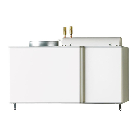
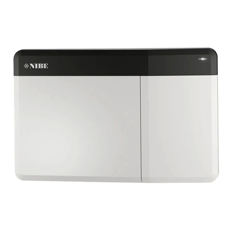
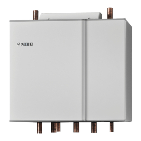
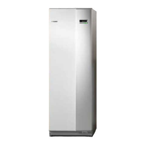
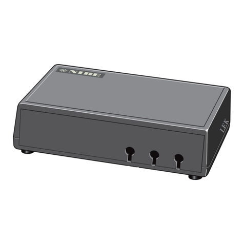
Nibe VVM 500 User manual

User manual
Indoor module
NIBE VVM 500
UHB EN 2235-1
731265

Quick guide
Navigation Ok button (confirm/select)
Back button (back/undo/exit)
Control knob (move/increase/reduce)
A detailed explanation of the button functions can be found on page 8.
How to scroll through menus and make different settings is described on page 10.
Set the indoor climate
2X
MY INSTALLATION
INDOOR CLIMATE HOT WATER
INFO
The mode for setting the indoor temperature is accessed by pressing the OK button twice, when in the start mode in
the main menu. Read more about the settings on page 13.
Increase hot water volume
2X
1X INDOOR CLIMATE HOT WATER
MY INSTALLATION INFO
To temporarily increase the amount of hot water, first turn the control knob to mark menu 2 (water droplet) and then
press the OK button twice. Read more about the settings on page 22.
In event of disturbances in comfort
If you experience any disturbance in comfort, there are some measures you can take yourself before you need to contact
your installer. See section "Disturbances in comfort" for instructions.

41 Important information
4Installation data
4Safety information
5Symbols
5Serial number
5VVM 500 – An excellent choice
6
2 The heating installation – the heart of the
house
6Installation function
8Contact with VVM 500
11Maintenance of VVM 500
12Saving tips
133 VVM 500 – at your service
13Set the indoor climate
22Set the hot water capacity
24Get information
26Adjust the indoor module
354 Disturbances in comfort
35Info-menu
35Manage alarm
36Troubleshooting
37Add. heat only
385 Technical data
396 Glossary
43Contact information
3Table of ContentsNIBE VVM 500
Table of Contents

Installation data
VVM 500Product
Serial number
Installation date
Installer
SetDefault settingsNameNo.
0temperature (heating curve offset)1.1
9heating curve (curve slope)1.9.1
20min. flow line temp.1.9.3
Accessories
Serial number must always be given.
Certification that the installation is carried out according to instructions in the accompanying installer manual and applicable regulations.
____________________________________________________________Signed_____________________________________Date
Safety information
This appliance can be used by children
aged from 8 years and above and per-
sons with reduced physical, sensory or
mental capabilities or lack of experience
and knowledge if they have been given
supervision or instruction concerning use
of the appliance in a safe way and under-
stand the hazards involved. Children shall
not play with the appliance. Cleaning and
user maintenance shall not be made by
children without supervision.
This is an original manual. It may not be
translated without the approval of NIBE.
Rights to make any design or technical
modifications are reserved.
©NIBE 2022.
VVM 500 must be installed via an isolator
switch. The cable area has to be dimen-
sioned based on the fuse rating used.
If the supply cable is damaged, only NIBE,
its service representative or similar author-
ised person may replace it to prevent any
danger and damage.
Do not start VVM 500 if there is a risk that
the water in the system has frozen.
MinMaxSystem
pressure
0.05 MPa
(0.5 bar)
0.3 MPa
(3 bar)
Heating me-
dium
0.01 MPa
(0.1 bar)
1.0 MPa
(10 bar)
Domestic
water
NIBE VVM 500Chapter 1 | Important information4
Important information

Symbols
Explanation of symbols that may be present in this manual.
NOTE
This symbol indicates danger to person or machine.
Caution
This symbol indicates important information about
what you should observe when maintaining your
installation.
TIP
This symbol indicates tips on how to facilitate us-
ing the product.
Serial number
The serial number can be found at the bottom right of the
front cover, in the info menu (menu 3.1) and on the type
plate.
Serial number
Caution
You need the product’s (14 digit) serial number for
servicing and support.
VVM 500 – An excellent choice
VVM 500 is an indoor module, which has been developed to
supply your home with inexpensive and environmentally
friendly heating and hot water in the most efficient manner.
The integrated hot water coil, immersion heater, circulation
pumps, solar coil and control system provide reliable and
economical heat production.
The indoor module can be connected to an optional low
temperature heat distribution system, e.g. radiators, con-
vectors or underfloor heating. It is also prepared for connec-
tion to a number of different products and accessories, e.g.
solar or other external heat source, extra water heater,
swimming pool and climate systems with different temper-
atures.
VVM 500 is equipped with a control computer for good
comfort, good economy and safe operation. Clear informa-
tion about status, operating time and all temperatures in
the system is shown on the large and easy to read display.
This means, for example, that external unit thermometers
are not necessary.
EXCELLENT PROPERTIES FOR VVM 500:
•Coil for hot water
There is a stainless steel hot water coil integrated in the
indoor module. The water in the coil is heated by the hot
water in the surrounding tank.
•Buffer vessel
There is a buffer vessel integrated in the indoor module
that equalises the temperature of the water that is sent
out in the climate system.
•Scheduling the indoor comfort and hot water
Heating and hot water can be scheduled for each day of
the week or for longer periods (vacation).
•Large display with user instructions
The indoor module has a large display with easy-to-under-
stand menus that facilitate setting a comfortable climate.
•Easy to install
The indoor module (VVM 500) is easy to install together
with a compatible NIBE air/water heat pump. When in-
stalling together with NIBE air/water heat pump, the heat
pump’s values can easily be read off from the indoor
module’s display.
•External heat source
VVM 500 is prepared for easy connection to a solar panel
installation and/or oil/gas/ wood fired boiler and district
heating.
5Chapter 1 | Important informationNIBE VVM 500

Förångare
Kondensor 80 °C
2 °C-3 °C
0 °C-7 °C
Expansionsventil Kompressor
A
D
F
B
C
E
Värmebärare
Köldmedium
Uteluft
55 °C45 °C
H
II
G
Heating medium
Värmebärare
Köldmedium
Köldbärare
Värmekälla
Förångare
Kondensor 100 °C
0 °C-3 °C
-2 °C
50 °C40 °C
Expansionsventil Kompressor
A
D
F
H
B
C
E
G
Outdoor air
Refrigerant
Evaporator
Condenser
Expansion valve Compressor
Heat source 1
2
3
The temperatures are only examples and may vary between different installations and time of year.
Installation function
An air/water heat pump installation uses the outdoor air to
heat up a home. The conversion of the outdoor air’s energy
into residential heating occurs in three different circuits.
From the outdoor air, (1) , free heat energy is retrieved and
transported to the heat pump. The heat pump increases the
retrieved heat’s low temperature to a high temperature in
the refrigerant circuit, (2) . The heat is distributed around
the building in the heating medium circuit, (3) .
NIBE VVM 500Chapter 2 | The heating installation – the heart of the house6
The heating installation – the heart
of the house

Outdoor air
The outdoor air is sucked into the heat pump.
A
The fan then routes the air to the heat pump’s evaporat-
or. Here, the air releases the heating energy to the refri-
gerant and the air's temperature drops. The cold air is
then blown out of the heat pump.
B
Refrigerant circuit
A gas circulates in a closed system in the heat pump, a
refrigerant, which also passes the evaporator. The refri-
gerant has a very low boiling point. In the evaporator the
refrigerant receives the heat energy from the outdoor
air and starts to boil.
C
The gas that is produced during boiling is routed into an
electrically powered compressor. When the gas is com-
pressed, the pressure increases and the gas's temperat-
ure increases considerably, from 0 °C to approx 80 °C.
D
From the compressor, gas is forced into a heat ex-
changer, condenser, where it releases heat energy to
the indoor module, whereupon the gas is cooled and
condenses to a liquid form again.
E
As the pressure is still high, the refrigerant can pass an
expansion valve, where the pressure drops so that the
refrigerant returns to its original temperature. The refri-
gerant has now completed a full cycle. It is routed to the
evaporator again and the process is repeated.
F
Heat medium circuit
The heat energy that the refrigerant produces in the
condenser is retrieved by the indoor module's water, the
heating medium, which is heated to 55 °C (supply tem-
perature).
G
The heating medium circulates in a closed system and
transports the heated water's heat energy to the house
radiators/heating coils.
H
The indoor module's integrated hot water heater is in
the boiler section. The hot boiler water heats the hot
water.
I
7Chapter 2 | The heating installation – the heart of the houseNIBE VVM 500

Contact with VVM 500
EXTERNAL INFORMATION
When the indoor module door is closed, information can be
received via an information window and a status lamp.
Information window
Status lamp
Information window
The information window shows part of the display that is
on the display unit (located behind the door to the indoor
module). The information window can display different types
of information, e.g. temperatures, clock, etc.
You determine what is to be displayed in the information
window. Your own combination of information is entered
using the display unit. This information is specific to the in-
formation window and disappears when the front hatch of
the indoor module door is opened.
Status lamp
The status lamp indicates the status of the indoor module:
continuous green light during normal function, continuous
yellow light during activated emergency mode or continuous
red light in the event of a deployed alarm.
Alarm management is described on page 35.
DISPLAY UNIT
A
B
C
D
E
F
Display
Status lamp
OK button
Back button
Control knob
Switch
INDOOR CLIMATE
MY SYSTEM INFO
HOT WATER
VVM500 GUSB port
There is a display unit behind the indoor module door, which
is used to communicate with VVM 500. Here you:
•switch on, switch off or set the installation to emergency
mode.
•set the indoor climate and hot water as well as adjust the
installation to your needs.
•receive information about settings, status and events.
•see different types of alarms and receive instructions
about how they are to be rectified.
Display
Instructions, settings and operational information are
shown on the display. You can easily navigate between
the different menus and options to set the comfort or
obtain the information you require.
A
Status lamp
The status lamp indicates the status of the indoor mod-
ule. It:
•lights green during normal operation.
•lights yellow in emergency mode.
•lights red in the event of a deployed alarm.
B
OK button
The OK button is used to:
•confirm selections of sub menus/options/set val-
ues/page in the start guide.
C
Back button
The back button is used to:
•go back to the previous menu.
•change a setting that has not been confirmed.
D
Control knob
The control knob can be turned to the right or left. You
can:
•scroll in menus and between options.
•increase and decrease the values.
•change page in multiple page instructions (for example
help text and service info).
E
Switch
The switch assumes three positions:
•On ()
•Standby ( )
•Emergency mode ( )
Emergency mode must only be used in the event of a
fault on the indoor module. In this mode, the compressor
switches off and the immersion heater engages. The in-
door module display is not illuminated and the status
lamp illuminates yellow.
F
USB port
The USB port is hidden beneath the plastic badge with
the product name on it.
The USB port is used to update the software.
Visit nibeuplink.com and click the "Software" tab to
download the latest software for your installation.
G
NIBE VVM 500Chapter 2 | The heating installation – the heart of the house8

MENU SYSTEM
When the door to the indoor module is opened, the menu
system’s four main menus are shown in the display as well
as certain basic information.
INDOOR CLIMATE
MY SYSTEM INFO
HOT WATER
Indoor temperature - (if room sensors are
installed)
Hot water temp.
Temporary lux (if
activated)
Outdoor
temperature
Estimated amount of hot
water
Information about
operation
MENU 1 - INDOOR CLIMATE
Setting and scheduling the indoor climate. See page 13.
MENU 2 - HOT WATER
Setting and scheduling hot water production. See page 22.
MENU 3 - INFO
Display of temperature and other operating information and
access to the alarm log. See page 24.
MENU 4 - MY SYSTEM
Setting time, date, language, display, operating mode etc.
See page 26.
Symbols in the display
The following symbols can appear in the display during op-
eration.
DescriptionSymbol
This symbol appears by the information sign if
there is information in menu 3.1 that you should
note.
These two symbols indicate whether the com-
pressor in the outdoor module or additional heat
is blocked in VVM 500.
These can, for example, be blocked depending on
which operating mode is selected in menu 4.2, if
blocking is scheduled in menu 4.9.5 or if an alarm
has occurred that blocks one of them.
Blocking the compressor.
Blocking additional heat.
This symbol appears if periodic increase or lux
mode for the hot water is activated.
This symbol indicates whether "holiday setting" is
active in 4.7.
This symbol indicates whether VVM 500 has con-
tact with NIBE Uplink.
This symbol indicates the actual speed of the fan
if the speed has changed from the normal setting.
Accessory needed.
This symbol is visible in installations with active
solar accessories.
This symbol indicates whether pool heating is act-
ive.
Accessory needed.
This symbol indicates whether cooling is active.
Heat pump with cooling function required.
9Chapter 2 | The heating installation – the heart of the houseNIBE VVM 500

Operation
To move the cursor, turn the control knob to the
left or the right. The marked position is white
and/or has a turned up tab.
Selecting menu
To advance in the menu system select a main menu by
marking it and then pressing the OK button. A new window
then opens with sub menus.
Select one of the sub menus by marking it and then pressing
the OK button.
Selecting options
economy
comfort mode 2.2
normal
luxury
smart control
In an options menu the current selected option is indic-
ated by a green tick.
To select another option:
1. Mark the applicable option. One of the options is
pre-selected (white).
2. Press the OK button to confirm the selected option.
The selected option has a green tick.
Setting a value
time & date 4.4
time
day
year
month
24 h
12 h
date
Values to be changed
To set a value:
1. Mark the value you want to set using the control
knob.
2. Press the OK button. The background of the value
becomes green, which means that you have ac-
cessed the setting mode.
3. Turn the control knob to the right to increase the
value and to the left to reduce the value.
4. Press the OK button to confirm the value you
have set. To change and return to the original
value, press the Back button.
NIBE VVM 500Chapter 2 | The heating installation – the heart of the house10

Use the virtual keyboard
Different keyboards
In some menus where text may require entering, a virtual
keyboard is available.
Depending on the menu, you can gain access to different
character sets which you can select using the control knob.
To change character table, press the Back button. If a menu
only has one character set the keyboard is displayed directly.
When you have finished writing, mark "OK” and press the OK
button.
Scroll through the windows
A menu can consist of several windows. Turn the control
knob to scroll between the windows.
Current menu
window
Number of
windows in the
menu
Scroll through the windows in the start guide
language 4.6
If the start guide is left on this page it
closes automatically in
60 min
Arrows to scroll through window in start guide
1. Turn the control knob until one of the arrows in the top
left corner (at the page number) has been marked.
2. Press the OK button to skip between the steps in the
start guide.
Help menu
In many menus there is a symbol that indicates that
extra help is available.
To access the help text:
1. Use the control knob to select the help symbol.
2. Press the OK button.
The help text often consists of several windows that you
can scroll between using the control knob.
Maintenance of VVM 500
REGULAR CHECKS
Your indoor module is, in principle, maintenance free and
therefore requires minimal care after commissioning. On
the other hand, it is recommended that you check your in-
stallation regularly.
If anything abnormal occurs, messages about the malfunc-
tion appear in the display in the form of various alarm texts.
See alarm management in section "Alarm".
Safety valve
The hot water coil’s externally mounted safety valve some-
times releases water after hot water usage. This is because
the cold water that enters the hot water coil expands when
heated, causing the pressure to rise and the safety valve to
open. The climate system’s externally fitted safety valve
must be completely sealed and normally does not release
any water.
The function of the safety valve should be checked regularly.
You can find the safety valve on the incoming pipe (cold
water). Perform checks as follows:
1. Open the valve.
2. Check that water flows through the valve.
3. Close the valve.
4. Check the system pressure, top up if required.
TIP
The safety valve is not supplied with the indoor
module. Contact your installer if you are unsure
how one checks the valve.
Check pressure
VVM 500 must be fitted with an external pressure gauge,
which shows the heating system pressure. The pressure
should be between 0.5 and 1.5 bar, but varies during temper-
ature changes. If the pressure drops to 0 or rises to 2.5 bar
frequently, contact your installer for troubleshooting.
Filling the climate system
If the pressure is too low in the climate system, it needs to
be topped up. See the Installer Manual for more information.
11Chapter 2 | The heating installation – the heart of the houseNIBE VVM 500

Venting the climate system
In event of repeated filling of the climate system, or if bub-
bling sounds are heard from the indoor module, the system
may need venting. This is done as follows:
1. Turn off the power supply to the indoor module.
2. Vent the indoor module via the vent valves and the rest
of the climate system via the relevant vent valves.
3. Keep topping up and venting until all air has been re-
moved and the pressure is correct.
The climate system may require topping up after venting.
Saving tips
Your installation produces heat and hot water. This occurs
via the control settings you made.
Factors that affect the energy consumption are, for example,
indoor temperature, hot water consumption, the insulation
level of the house and whether the house has many large
window surfaces. The position of the house, e.g. wind expos-
ure is also an affecting factor.
Also remember:
•Open the thermostat valves completely (except in rooms
where you want it to be cooler). This is important, as fully
or partially closed thermostat valves slow the flow in the
climate system, which results in VVM 500 working at a
higher temperature. This in turn can lead to increased
energy consumption.
•You can lower the operating cost when away from home
by scheduling selected parts of the system. This is done
in menu 4.7 "holiday setting". See page 32 for instructions.
•If you activate "economy" in menu 2.2 "comfort mode",
less energy is used.
•You can influence the energy consumption by connecting
the indoor module to different supplements such as solar,
gas or oil.
POWER CONSUMPTION
Approximate energy consumption for VVM 500
spread across the year
Energiförbrukning fördelat över året
0%
5%
10%
15%
20%
25%
jan feb mars april maj juni juli aug sep okt nov dec
Månad
% av årsförbrukningen
Month
Jan Feb Mar April May June July Aug Sep Oct Nov Dec
% of annual
consumption
Increasing the indoor temperature by one degree increases
the energy consumption by approx. 5 %.
Energy meter
Check the accommodation's energy meter regularly,
preferably once a month. This will indicate any changes in
power consumption.
Newly built houses usually have twin energy meters, use
the difference to calculate your domestic electricity.
New builds
Newly built houses undergo a drying out process for a year.
The house can then consume significantly more energy than
it would thereafter. After 1-2 years the heating curve should
be adjusted again, as well as the offset heating curve and
the building's thermostat valves, because the heating sys-
tem, as a rule, requires a lower temperature once the drying
process is complete.
NIBE VVM 500Chapter 2 | The heating installation – the heart of the house12

Set the indoor climate
OVERVIEW
Sub-menus
temperature
INDOOR CLIMATE 1
ventilation
scheduling
advanced
off
normal
For the menu IN-
DOOR CLIMATE there
are several sub-
menus. Status inform-
ation for the relevant
menu can be found
on the display to the
right of the menus.
temperature Setting
the temperature for the climate system. The status inform-
ation shows the set values for the climate system.
ventilation Setting the fan speed. The status information
shows the selected setting. This menu is only displayed if
the exhaust air module is connected (accessory).
scheduling Scheduling heating, cooling and ventilation.
Status information "set" is displayed if you set a schedule
but it is not active now, "holiday setting" is displayed if the
vacation schedule is active at the same time as the schedule
(the vacation function is prioritised), "active" displays if any
part of the schedule is active, otherwise it displays " off".
advanced Setting of heat curve, adjusting with external
contact, minimum value for supply temperature, room
sensor, cooling function and +Adjust.
MENU 1.1 - TEMPERATURE
temperature heating 1.1.1
temperature cooling 1.1.2
If the house has sever-
al climate systems,
this is indicated on
the display by a ther-
mometer for each
system.
Choose between
heating or cooling and
then set the desired
temperature in the
next menu "temperat-
ure heating/cooling"
in menu 1.1.
Set the temperature (with room sensor
installed and activated):
heating
Setting range: 5 – 30 °C
Default value: 20
cooling (accessory required)
Setting range: 5 – 30 °C
Default value: 25
The value in the display appears as a temperature in °C if
the climate system is controlled by a room sensor.
Caution
A slow heating system such as underfloor heating
may not be suitable for control using the indoor
module’s room sensors.
To change the room temperature, use the control knob to
set the desired temperature in the display. Confirm the new
setting by pressing the OK button. The new temperature is
shown on the right-hand side of the symbol in the display.
Setting the temperature (without room
sensors activated):
Setting range: -10 to +10
Default value: 0
The display shows the set values for heating (curve offset).
To raise or lower the indoor temperature, increase or reduce
the value on the display.
Use the control knob to set a new value. Confirm the new
setting by pressing the OK button.
The number of steps the value has to be changed to achieve
a degree change of the indoor temperature depends on the
heating installation. One step is usually enough but in some
cases several steps may be required.
Setting the desired value. The new value is shown on the
right-hand side of the symbol in the display.
Setting the relative humidity: (accessory is
required)
Setting range: 30 to 90 %
Factory setting: 60 %
The menu is only displayed if limit RH is activated in menu
5.3.16.
13Chapter 3 | VVM 500 – at your serviceNIBE VVM 500
VVM 500 – at your service

The display shows the value set for relative humidity. To
change how VVM 500 is run, in relation to relative humidity,
increase or decrease the value given on the display.
Use the control knob to set the required value. Confirm the
new setting, by pressing the OK button.
Caution
An increase in the room temperature can be
slowed by the thermostats for the radiators or
under floor heating. Therefore, open the thermo-
stats fully, except in those rooms where a cooler
temperature is required, e.g. bedrooms.
TIP
Wait 24 hours before making a new setting, so that
the room temperature has time to stabilise.
If it is cold outdoors and the room temperature is
too low, increase the curve slope in menu 1.9.1.1
by one increment.
If it is cold outdoors and the room temperature is
too high, reduce the curve slope in menu 1.9.1.1 by
one increment.
If it is warm outdoors and the room temperature
is too low, increase the value in menu 1.1.1 by one
increment.
If it is warm outdoors and the room temperature
is too high, reduce the value in menu 1.1.1 by one
increment.
MENU 1.2 - VENTILATION (ACCESSORY RE-
QUIRED)
normal (50%)
ventilation 1.2
speed 1 (0%)
speed 2 (40%)
speed 3 (80%)
speed 4 (100%)
Setting range: nor-
mal and speed 1-4
Default value: nor-
mal
The ventilation in the accommodation can be temporarily
increased or reduced here.
When you have selected a new speed a clock starts a count
down. When the time has counted down the ventilation
speed returns to the normal setting.
If necessary, the different return times can be changed in
menu 1.9.6.
The fan speed is shown in brackets (in percent) after each
speed alternative.
TIP
If longer time changes are required use the holiday
function or scheduling.
Caution
The ventilation accessory requires a minimum
ventilation flow in order to work properly. An insuf-
ficient ventilation flow can result in an alarm and
blocking of compressor operation.
MENU 1.3 - SCHEDULING
scheduling 1.3
cooling
ventilation off
off
heating off
In the menu
scheduling indoor
climate (heating/cool-
ing/ventilation) is
scheduled for each
weekday.
You can also schedule
a longer time during a
selected period (holi-
day) in menu 4.7.
MENU 1.3.1 - HEATING
Increases or decreases in the accommodation temperature
can be scheduled here for up to three time periods per day.
If a room sensor is installed and activated the desired room
temperature (°C) is set during the time period. Without an
activated room sensor the desired change is set (of setting
in menu 1.1). One step is usually enough to change the room
temperature by one degree, but in some cases several steps
may be required.
SCHEDULING HEATING 1.3.1
activated
schedule 2
system
schedule 3schedule 1
all
mon
tues
wed
thur
fri
sat
sun
21:30 -
06:00 20.5°
Time period AdjustingDay
Activated Schedule System
Conflict
Schedule: The schedule to be changed is selected here.
Activated: Scheduling for the selected period is activated
here. Set times are not affected at deactivation.
NIBE VVM 500Chapter 3 | VVM 500 – at your service14

System: The climate system that the relevant schedule
relates to is selected here. This alternative is only displayed
if there is more than one climate system.
Day: Select which day or days of the week the scheduling
is to apply to here. To remove the scheduling for a particular
day, the time for that day must be reset by setting the start
time to the same as the stop time. If the row "all" is used, all
days in the period are set according to that row.
Time period: The start and stop time for the selected day
for scheduling are selected here.
Adjustment: How much the heating curve is to be offset in
relation to menu 1.1 during scheduling is set here. If a room
sensor is installed, the desired room temperature is set in
°C.
Conflict: If two settings conflict with each other, a red ex-
clamation mark is displayed.
TIP
If you wish to set similar scheduling for every day
of the week start by filling in “all” and then chan-
ging the desired days.
TIP
Set the stop time earlier than the start time so that
the period extends beyond midnight. Scheduling
then stops at the set stop time the day after.
Scheduling always starts on the date that the start
time is set for.
Caution
Changes of temperature in accommodation take
time. For example, short time periods in combina-
tion with underfloor heating will not give a notice-
able difference in room temperature.
MENU 1.3.2 - COOLING (ACCESSORY RE-
QUIRED)
Here you can schedule when cooling is permitted in the ac-
commodation for up to two different time periods per day.
SCHEDULING COOLING 1.3.2
activated
schedule 2schedule 1
all
mon
tues
wed
thur
fri
sat
sun
21:30 -
06:00 on
Activated Schedule
Time period AdjustingDay Conflict
Schedule: The schedule to be changed is selected here.
Activated: Scheduling for the selected period is activated
here. Set times are not affected at deactivation.
Day: Select which day or days of the week the scheduling
is to apply to here. To remove the scheduling for a particular
day, the time for that day must be reset by setting the start
time to the same as the stop time. If the row "all" is used, all
days in the period are set according to that row.
Time period: The start and stop time for the selected day
for scheduling are selected here.
Adjustment: Here, you schedule when cooling will not be
permitted.
Conflict: If two settings conflict with each other, a red ex-
clamation mark is displayed.
TIP
If you wish to set similar scheduling for every day
of the week start by filling in “all” and then chan-
ging the desired days.
TIP
Set the stop time earlier than the start time so that
the period extends beyond midnight. Scheduling
then stops at the set stop time the day after.
Scheduling always starts on the date that the start
time is set for.
MENU 1.3.3 - VENTILATION (ACCESSORY RE-
QUIRED)
Increases or decreases in the ventilation to the accommod-
ation can be scheduled here for up to two time periods per
day.
15Chapter 3 | VVM 500 – at your serviceNIBE VVM 500

all
mon
tues
wed
thur
fri
sat
sun
activated
schedule 2schedule 1
SCHEDULING VENTILATION 1.3.3
21:30 -
06:00 speed 3
Activated Schedule
Time period AdjustingDay Conflict
Schedule: The schedule to be changed is selected here.
Activated: Scheduling for the selected period is activated
here. Set times are not affected at deactivation.
Day: Select which day or days of the week the scheduling
is to apply to here. To remove the scheduling for a particular
day, the time for that day must be reset by setting the start
time to the same as the stop time. If the row "all" is used, all
days in the period are set according to that row.
Time period: The start and stop time for the selected day
for scheduling are selected here.
Adjustment: The desired fan speed is set here.
Conflict: If two settings conflict with each other, a red ex-
clamation mark is displayed.
TIP
If you wish to set similar scheduling for every day
of the week start by filling in “all” and then chan-
ging the desired days.
TIP
Set the stop time earlier than the start time so that
the period extends beyond midnight. Scheduling
then stops at the set stop time the day after.
Scheduling always starts on the date that the start
time is set for.
Caution
A significant change over a longer period of time
may cause poor indoor environment and worse
operating economy.
MENU 1.9 - ADVANCED
advanced 1.9
heating curve
external adjustment
min. flow line temp.
room sensor settings
cooling settings
fan return time
Menu advanced has
orange text and is in-
tended for the ad-
vanced user. This
menu has several
sub-menus.
curve Setting the
curve slope for heat-
ing and cooling.
external adjustment Setting the heat curve offset when
the external contact is connected.
min. flow line temp. Setting minimum permitted flow line
temperature.
room sensor settings Settings regarding the room sensor.
cooling settings Settings for cooling.
fan return time Fan return time settings in the event of
temporary ventilation speed change.
own curve Setting own curve for heating and cooling.
point offset Setting the offset of the heating curve or
cooling curve at a specific outdoor temperature.
night cooling Setting night cooling.
+Adjust Setting how much effect +Adjust will have on
calculated supply temperature for underfloor heating. The
higher the value is the greater the effect.
MENU 1.9.1 - CURVE
heating curve
heating curve 1.9.1.1
system
outdoor temp. °C
flow temperature °C
Setting range: 0 –
15
Default value: 9
cooling curve
cooling curve 1.9.1.2
system
outdoor temp. °C
flow temperature °C
Setting range: 0 –
9
Default value: 0
The prescribed heating curve for your house can be viewed
in the menu curve . The task of the heating curve is to give
an even indoor temperature, regardless of the outdoor
temperature, and thereby energy efficient operation. It is
from this heating curve that the indoor module’s control
computer determines the temperature of the water to the
NIBE VVM 500Chapter 3 | VVM 500 – at your service16

heating system, supply temperature, and therefore the in-
door temperature. Select the heating curve and read off
how the supply temperature changes at different outdoor
temperatures here. If there is access to cooling the same
settings can be made for the cooling curve.
17Chapter 3 | VVM 500 – at your serviceNIBE VVM 500

Caution
With underfloor heating systems, max flow line
temperature should normally be set to between
35 and 45 °C.
With underfloor cooling, "min. flow line temp." must
be restricted to prevent condensation.
Check the max temperature for your floor with
your installer/floor supplier.
TIP
Wait 24 hours before making a new setting, so that
the room temperature has time to stabilise.
If it is cold outdoors and the room temperature is
too low, increase the curve slope by one incre-
ment.
If it is cold outdoors and the room temperature is
too high, lower the curve slope by one increment.
If it is warm outdoors and the room temperature
is too low, increase the curve offset by one incre-
ment.
If it is warm outdoors and the room temperature
is too high, lower the curve offset by one incre-
ment.
Cooling in 2-pipe system
VVM 500 contains a built-in function for operating cooling
in a 2-pipe system down to 17 °C, factory setting 18 °C. This
requires that the outdoor unit can perform cooling. (See the
Installer Manual for your air/water heat pump.) If the outdoor
unit can perform cooling, the cooling menus are activated
in the display on the indoor module (VVM).
In order for operating mode “cooling” to be permitted, the
average temperature must be above the setting value for
“start cooling” in menu 4.9.2
The cooling settings for the climate system are adjusted in
the indoor climate menu, menu 1.
MENU 1.9.2 - EXTERNAL ADJUSTMENT
external adjustment 1.9.2
climate system 1
climate system 2
climate system 3
climate system 4
°C
°C
Set the
temperature
(with room
sensor
installed and
activated):
Setting range: 5 –
30 °C
Default value: 20
Setting the temperature (without room
sensors activated):
Setting range: -10 to +10.
Default value: 0
Connecting an external contact, for example, a room ther-
mostat or a timer allows you to temporarily or periodically
raise or lower the room temperature while heating. When
the contact is on, the heating curve offset is changed by
the number of steps selected in the menu. If a room sensor
is installed and activated the desired room temperature (°C)
is set.
If there is more than one climate system the setting can be
made separately for each system.
MENU 1.9.3 - MIN. FLOW LINE TEMP.
min. flow line temp. heating 1.9.3.1
climate system 1
climate system 2
climate system 3
climate system 4
°C
°C
°C
°C
20
20
20
20
min. flow line temp. cooling 1.9.3.2
climate system 1
climate system 2
climate system 3
climate system 4
°C
°C
°C
°C
18
18
18
18
heating
Setting range: 5-
70 °C
Default value: 20
°C
cooling
(accessory
required)
Factory setting:
18 °C
In menu 1.9.3 you select heating or cooling, in the next menu
(min. supply temp.heating/cooling) set the minimum tem-
perature on the supply temperature to the climate system.
This means that VVM 500 never calculates a temperature
lower than that set here.
If there is more than one climate system the setting can be
made separately for each system.
NIBE VVM 500Chapter 3 | VVM 500 – at your service18

TIP
The value can be increased if you have, for ex-
ample, a cellar that you always want to heat, even
in summer.
You may also need to increase the value in "stop
heating" menu 4.9.2 "auto mode setting".
MENU 1.9.4 - ROOM SENSOR SETTINGS
room sensor settings 1.9.4
heating factor system 1
control room sensor syst 2
control room sensor syst 3
cooling factor system 1
control room sensor syst
control room sensor syst 4
factor system
heating
Setting range: 0.0
- 6.0
Factory setting
heating: 1.0
cooling
(accessory
required)
Setting range: 0.0 - 6.0
Factory setting cooling: 1.0
Room sensors to control the room temperature can be activ-
ated here.
Caution
A slow heating system such as underfloor heating
may not be suitable for control using the installa-
tion’s room sensors.
Here you can set a factor (a numerical value) that determines
how much an over or sub normal temperature (the difference
between the desired and actual room temperature) in the
room is to affect the supply temperature to the climate
system. A higher value gives a greater and faster change of
the heating curve's set offset.
NOTE
Too high a set value for "factor system" can (de-
pending on your climate system) produce an un-
stable room temperature.
If several climate systems are installed the above settings
can be made for the relevant systems.
MENU 1.9.5 - COOLING SETTINGS (ACCESSORY
REQUIRED)
cooling 1.9.5
set pt value cool/heat sensor
heat at room under temp.
cool at room over temp.
use room sensor
°C
°C
°C
delta at +20
°C
Setting range: 3 -
10 °C
Default value: 3
delta at +40
°C
Setting range: 3 -
10 °C
Default value: 6
cool/heat sensor
Factory setting: no sensor selected
set pt value cool/heat sensor
Setting range: 5 - 40 °C
Default value: 21
heat at room under temp.
Setting range: 0.5 - 10.0 °C
Default value: 1.0
cool at room over temp.
Setting range: 0.5 - 10.0 °C
Default value: 1.0
larm rumsgivare kyla
Setting range: on/off
Factory setting: off
start active cooling
Setting range: 10 – 300
Default value: 0
degree minutes cooling
Setting range: -3000 – 3000 cooling degree minutes
Factory setting: 0
time betw. switch heat/cool (Displayed if
cooling in 2-pipe system is activated.)
Setting range: 0 – 48 h
Factory setting: 2
op mode auto EQ1-GP12
Here, you set whether you want the cooling pump (GP12)
to run in operating mode auto.
cooling pump speed
Setting range: 1 – 100 %
Factory setting: 70 %
19Chapter 3 | VVM 500 – at your serviceNIBE VVM 500

You can use VVM 500 to cool the house during hot periods
of the year.
Caution
Certain setting options only appear if their function
is installed and activated in VVM 500.
delta at +20 °C
Set the desired temperature on the temperature difference
between supply and return lines to the climate system during
cooling operation when the outdoor temperature is +20 °C.
VVM 500 then attempts to get as close to the set temperat-
ure as possible.
delta at +40 °C
Set the desired temperature on the temperature difference
between supply and return lines to the climate system during
cooling operation when the outdoor temperature is +40 °C.
VVM 500 then attempts to get as close to the set temperat-
ure as possible.
use room sensor
Here you can set whether room temperature sensors are to
be used in cooling mode.
cool/heat sensor
An extra temperature sensor can be connected to VVM 500
in order to determine when it is time to switch between
heating and cooling operation.
When several heating/cooling sensors are installed, you can
select which one of them should be in control.
Caution
When the heating/cooling sensors BT74 have been
connected and activated in menu 5.4, no other
sensor can be selected in menu 1.9.5.
set pt value cool/heat sensor
Caution
This setting option only appears if a room sensor
for cooling/heating is installed and activated in
VVM 500.
Here you can set at which indoor temperature VVM 500 is
to shift between heating respectively cooling operation.
heat at room under temp.
Caution
This setting option only appears if a room temper-
ature sensor is connected to VVM 500 and has
been activated.
Here you can set how far the room temperature can drop
below the desired temperature before VVM 500 switches
to heating operation.
cool at room over temp.
Caution
This setting option only appears if a room temper-
ature sensor is connected to VVM 500 and has
been activated.
Here you can set how high the room temperature can in-
crease above the desired temperature before VVM 500
switches to cooling operation.
larm rumsgivare kyla
This is where you set whether VVM 500 is to initiate an alarm
if the room sensor is disconnected or breaks during cooling
operation.
start active cooling
Caution
This setting option only appears if "active cooling"
is activated in menu 5.2.4.
Here you can set when active cooling is to start.
Degree minutes are a measurement of the current heating
demand in the house and determine when the compressor,
cooling operation respectively additional heat will start/stop.
degree minutes cooling
This selection is only available when the connected access-
ory itself counts cooling degree minutes.
After a min or max value has been set, the system will
automatically set the actual value if the air/water heat pump
is running cooling.
time betw. switch heat/cool
This selection is only available when cooling in 2-pipe sys-
tems.
Here you can set how long VVM 500 is to wait before it re-
turns to heating mode when the cooling demand has ceased
or vice versa.
MENU 1.9.6 - FAN RETURN TIME (ACCESSORY
REQUIRED)
fan return time 1.9.6
speed 1
speed 2
speed 3
speed 4
hrs
hrs
hrs
hrs
speed 1-4
Setting range: 1 –
99 h
Default value: 4 h
Here you select the return time for temporary speed change
(speed 1-4) on the ventilation in menu 1.2.
Return time is the time it takes before ventilation speed re-
turns to normal.
NIBE VVM 500Chapter 3 | VVM 500 – at your service20
Other manuals for VVM 500
7
Table of contents
Other Nibe Control Unit manuals