NSK M500L User manual

OM-T0345E 004

1
ENGLISH
CAUTION
· Read this Operation Manual before use to fully understand the product functions and file for future reference.
· When operating the handpiece always consider the safety of the patient.
· Do not attempt to disassemble the handpiece nor tamper with the mechanism.
· Check for vibration, noise and overheating outside the patient's mouth. If any abnormalities are found do not operate. Contact authorized dealer for service.
· Should the handpiece not function normally, cease operation immediately and return the handpiece to your authorised NSK Dealer for service.
·
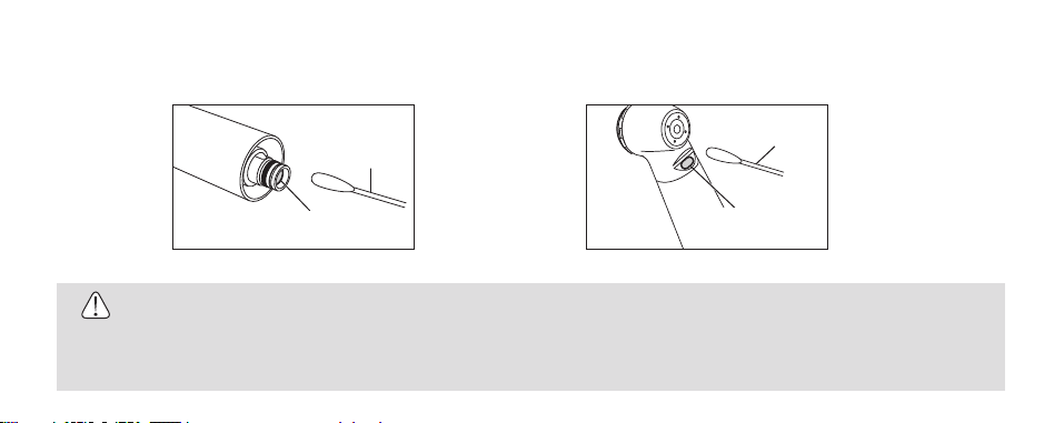
Depressing the chuck push button system while the bur is rotating could result in OVERHEATING of the handpiece head. Caution must be exercised during use to keep
cheek tissue away from the chuck push button system. Contact with soft tissue may cause the push button to depress and burn injury to the patient may occur.
· Avoid impact on the handpiece. Do not drop the handpiece.
· Remove the bur only after the handpiece has completely stopped rotating.
· Do not use long surgical burs. Do not use burs longer than 26mm.
· This product is classified as Class 1 LED Product. (M500WLED, M500BLED, M600WLED, M600BLED)
· Do not fixate the eyes of LED light.(M500WLED, M500BLED, M600WLED, M600BLED)
· If any abnormalities (dark, do not light on or flashing)are found for LED, stop using the product immediately and contact authorized dealer. (M500WLED,
M500BLED, M600WLED, M600BLED)
· Use the power source with the supply capability of 15W or less for LED lighting.
· Use a power source which meets the following requirements. (M500WLED, M500BLED, M600WLED, M600BLED)
1. The electricity supply of the power source is below 15W both under normal and single failure conditions.
Intended Use : This handpiece is designed only for dental treatment use.

2
2. The power source uses a SELV circuit for electricity supply.
3. The output voltage of the power source is within the range recommended by the manufacturer of this product.
1. Specification
Consumption
current
Activate Voltage
Friction Grip Standard Shank
Friction Grip Short/Standard Shank
Push Button Chuck
Size: ISO1797-1 Type3 ø1.59~1.60mm
-
Glass Rod
- White LED -
Glass Rod
Glass Rod
-
-
-
-
-
-
-
0.38A Typical
(3.3V)
2.8 - 4.0 V
AC/DC
3.3±0.05V
0.38A Typical
(3.3V)
2.8 - 4.0 V
AC/DC
3.3±0.05V
White LED
0.25MPa (2.5kgf/cm2)~0.3MPa (3.0kgf/cm2)
Miniature Head
M500
M500L
380,000~450,000min-1
M500K
M500KL/M500SL/
M500WL/M500BL
M500WLED
M500BLED
M600
M600L
Standard Head
360,000~430,000min-1
M600KL/M600SL/
M600WL/M600BL
0.20MPa (2.0kgf/cm2)
~0.25MPa (2.5kgf/cm2)
0.20MPa (2.0kgf/cm2)
~0.25MPa (2.5kgf/cm2)
0.25MPa (2.5kgf/cm2)~0.3MPa ( 3.0kgf/cm2)
M600K
M600WLED
M600BLED
Glass Rod
Model
Head Type
Rotation Speed
Drive Air Pressure
Chuck Type
Burs
Optic
Voltage

3
ENGLISH GERMAN FRENCH SPANISH ITALIAN
2. Connection / Disconnection to the Coupling
First make sure the manufacturer’s coupling is firmly attached to the handpiece tubing and
the drive air pressure is correct.
CONNECTION (Fig.1)
To connect the handpiece to the coupling align the handpiece to the coupling and push
together (per the coupling manufacturers instructions).
DISCONNECTION (Fig.1)
Release the handpiece from the coupling (per the coupling manufacturers instructions) and
remove the handpiece.
NSK COUPLING : Pull back Connector Ring to release the handpiece.
Fig. 1
Handpiece
NSK Coupling
Connector Ring

4
3. Insertion & Removal of the bur
TO INSERT THE BUR (Fig. 2)
Depress the Push Button and insert the bur into the chuck until it is secure. Release the button.
TO REMOVE THE BUR (Fig. 3)
Stop the handpiece. Depress the Push Button firmly and remove the bur.
1
2
Fig. 2
2
1
Fig. 3
CAUTION
Test that the bur is secure by gently pulling and pushing the bur without depressing the Push
Button.

5
ENGLISH GERMAN FRENCH SPANISH ITALIAN
4. Information about burs
· Do not use non-standard burs. The ISO standard shank diameter is ø1.59 - ø1.60 mm.
· Do not use bent, worn, damaged, or non-concentric burs. Such burs can cause damage to the handpiece.
· Do not exceed the bur speed recommended by the bur manufacturer.
· Always keep the bur shank clean. Entry of hard debris into the chuck via the bur shank could cause rotation slip and also prevent the bur from being
securely located in the chuck.
· Fully depress the Push Button and insert the bur into the chuck until it is secure.
· Do not use short shank burs in Standard Head handpieces.
5. Lubrication, Cleaning and Sterilization
Refer to the Maintenance Guide OM-Z0135E.
All handpieces can be cleaned and disinfected with a Thermo-Disinfector.
All handpieces can be autoclavable up to Max.135°C.

6
6. Replacing the optic illumination bulb (M500WL, M600WL, M500BL, M600BL Series)
Remove the handpiece from the coupling. Loosen and remove the Taper Ring. (Fig. 4).
Pull out the joint then remove the bulb holder, then the bulb.Align the pins of the new
bulb with the points in the bulb holder and insert the bulb. Place the bulb holder back
into the joint. (Fig. 5).
Firmly tighten the Taper Ring.
Optional Bulb : TA Bulb (Pack of 3) Order No.Y900132
Figure shows M500WL/,M600WL
CAUTION
· Do not touch the glass section of new bulb.
· Screw the taper ring tightly. A loose fitting taper ring could
result in water and air leakage. It is easier to screw in the
taper ring when the bulb holder is lightly pressed in by hand.
Fig. 4
Taper Ring
Fig. 5
Bulb Bulb Holder
Joint
<M500WL, M600WL>
Bulb Bulb Holder
Joint
<M500BL, M600BL>

7
ENGLISH GERMAN FRENCH SPANISH ITALIAN
7. Replacing the O-rings (M500L, M500, M600L, M600 Series)
Replace the O-rings if water is present in the exhaust air line. This is an indication of possible water leakage
within the coupling. ALWAYS change the complete set of O-rings. Remove the handpiece from the coupling.
Loosen and remove the Taper Ring at the rear of the handpiece. (Fig. 4) Gently remove each O-ring with your
thumb. Insert the complete set of new O-rings in the correct grooves. (Fig. 6). Replace and firmly tighten the
Taper Ring.
Optional O-ring : PTL O-ring Set (Pack of 5) Order No.Y900580
O-rings
Fig. 6
CAUTION
· Make certain that the Taper Ring is firmly tightened. If the Taper Ring is loose water and air leakage could occur.
· Do not disassemble the taper-ring except the O-ring changing.

8
CAUTION
Do not use a sharp tool to clean the cellular glass optic rod. It could damage the glass and reduce the light transmission. If illumination becomes
dim please contact your dealer.
Wipe clean the cellular glass optic rod entry point (Fig. 7) and exit point (Fig. 8) with an alcohol-immersed cotton swab. Remove all debris and oil.
Fig. 8
Cotton Swab
Cellular glass optic rod
exit point
Cotton Swab
Cellular glass optic rod
entry point
Fig. 7
8.
Cleaning the cellular glass optic rod
(M500L, M600L, M500KL, M600KL, M500SL, M600SL, M500WL, M600WL, M500WLED, M600WLED, M500BL, M600BL, M500BLED, M600BLED)

9
ENGLISH GERMAN FRENCH SPANISH ITALIAN
9. Replacing the Turbine Cartridge
(1) Remove the turbine cartridge from the handpiece
1) Insert a bur into the chuck.
2) Locate the head cap wrench tool on the head cap then turn the
wrench counter-clockwise. Remove the cap.
3) Use the bur to gently lever the entire turbine cartridge out of the
head.
4) Remove debris from inside the empty head.
(2) Insert a new NSK turbine cartridge
1) Gently insert the new NSK turbine cartridge into the head section,
always making certain that the turbine cartridge locating pin is
aligned in the slot inside the head.
2) Use fingers to screw the head cap back into place and then use the
cap wrench to further tighten until the cap is securely in place.
Optional Cartridge : SX-MU03 (Cartridge for Miniature head) Order No.P1001250
SX-SU03 (Cartridge for Standard head) Order No.P1002250
Head Cap
Head Cap Wrench
Locating Pin
Slot
Cartridge
Fig. 9

10
Consult with dealer from whom you purchased it about waste disposal.
10. Disposing product
Fig. 10
CAUTION
· Use only the genuine NSK-manufactured turbine cartridge. Do not use repaired or re-built NSK turbine cartridge.
Non-conformance to this shall immediately void the manufacturer's warranty, and the manufacturer shall have
no liability to the user and the patient for any incident that may arise from use of such turbine cartridge.
· The head cap screw thread is very fine. To prevent damage to the thread always first tighten the handpiece head
cap using fingers, then secure with the head cap wrench.
· Make sure that the two O-rings (Fig.10) are correctly located on the cartridge.
· Use only NSK genuine cartridge. If you use our cartridge, specification may not be satisfied and we can not
warranty of this situation.
O-ring
O-ring
KaVo®and MULTIflex®are registered trademarks of Kaltenbach & Voigt GmbH & Co., Germany. Sirona®is a registered trademark of Sirona Dental Systems GmbH, Germany.
W&H®and Roto Quick®are registered trademarks of W&H Dentalwerk Bürmoos GmbH,Austria. Bien-Air®and Unifix®are registered trademarks of Bien-Air Dental S.A.,Switzerland.

11
DEUTSCH
· Lesen Sie diese Betriebsanleitung vor dem Gebrauch sorgfältig durch und machen Sie sich mit allen Bedienungsfunktionen vertraut. Bewahren Sie die
Betriebsanleitung so auf, dass sie für die zukünftige Verwendung leicht auffindbar ist.
· Bei Verwendung der Turbine muss immer die Patientensicherheit beachtet werden.
· Versuchen Sie nicht, die Turbine zu zerlegen und nehmen Sie keine Eingriffe am Mechanismus vor.
· Prüfen Sie Vibration, Betriebsgeräusch und Erhitzung außerhalb der Mundhöhle des Patienten. Falls anormale Zustände vorgefunden werden, beenden
Sie den Betrieb. Wenden Sie sich zur Wartung an Ihren NSK-Fachhändler.
·
Sollte eine anormale Funktion an der Turbine auftreten, beenden Sie den Betrieb sofort und reichen die Turbine beim autorisieren NSK-Fachhändler zur Reparatur ein.
· Das Drücken des Druckknopf-Spannsystems bei rotierendem Bohrer könnte zu einer ÜBERHITZUNG des Turbinenkopfs führen. Während der
Verwendung muss sorgfältig darauf geachtet werden, die Wange vom Druckknopf-Spannsystem fernzuhalten. Bei Kontakt mit Weichgewebe kann der
Druckknopfdeckel eingedrückt werden und eine Verbrennung des Patienten auftreten.
· Schützen Sie die Turbine vor Stößen, lassen Sie die Turbine nicht fallen.
· Entfernen Sie den Bohrer erst, wenn die Turbine vollständig zum Stillstand gekommen ist.
· Verwenden Sie keine langen chirurgischen Bohrer. Verwenden Sie keine Bohrer, die länger sind als 26 mm.
· Dieses Produkt ist als LED-Produkt der Klasse 1 eingestuft. (M500WLED, M500BLED, M600WLED, M600BLED)
· Nicht starr in de LED-Beleuchtung blicken. (M500WLED, M500BLED, M600WLED,M600BLED)
· Wenn Störungen des LED-Displays auftreten (dunkel, leuchtet nicht oder blinkt), stellen Sie die Benutzung des Produkts sofort ein und wenden Sie sich
an den Händler. (M500WLED, M500BLED, M600WLED,M600BLED)
· Benutzen Sie die Stromquelle mit der Leistungsfähigkeit von 15W oder weniger für die LED-Beleuchtung.
· Benutzen Sie eine Stromquelle, die die folgenden Anforderungen erfüllt. (M500WLED, M500BLED, M600WLED, M600BLED)
1. Die Stromversorgung der Stromquelle liegt sowohl unter normalen Bedingungen als auch im Fehlerfall unter 15W.
VORSICHT
Vorgesehene Verwendung : Diese Turbine ist nur für die zahnärztliche Behandlung vorgesehen.

12
2. Die Stromquelle verwendet ein SELV-Kreis für die Stromversorgung.
3. Die Ausgangsspannung der Stromquelle befindet sich innerhalb des vom Hersteller dieses Produkts empfohlenen Bereichs.
1. Caratéristiques Techniques
Verbrauchsstrom
Aktivierungsspannung
FG–Standardschaft
FG–Kurzschaft/Standardschaft
Druckknopf-Spannsystem
Größe : ISO1797-1 Typ3 ø1,59~1,60mm
-
Glass Rod
- Weiße LED -
Glasstaboptik
Glasstaboptik
-
-
-
-
-
-
-
0,38A Typisch
(3,3V)
2,8 - 4,0 V
AC/DC
3,3±0,05V
0,38A Typisch
(3,3V)
2,8 - 4,0 V
AC/DC
3,3±0,05V
Weiße LED
0,25MPa (2,5kgf/cm2)~0,3MPa (3,0kgf/cm2)
Miniaturkopf
M500
M500L
380.000~450.000min-1
M500K
M500KL/M500SL/
M500WL/M500BL
M500WLED
M500BLED
M600
M600L
Standardkopf
360.000~430.000min-1
M600KL/M600SL/
M600WL/M600BL
0,20MPa (2,0kgf/cm2)
~0,25MPa (2,5kgf/cm2)
0,20MPa (2,0kgf/cm2)
~0,25MPa (2,5kgf/cm2)
0,25MPa (2,5kgf/cm2)~0,3MPa ( 3,0kgf/cm2)
M600K
M600WLED
M600BLED
Glasstaboptik
Modell
Kopftyp
Drehzahl
Antriebsluftdruck
Futtertyp
Bohrer
Zellularer Glasstab
Spannung

13
ENGLISCH DEUTSCH FRANZÖSISCH SPANISCH ITALIENISCH
2. Anschließen an/abnehmen von der Kupplung
Stellen Sie zuerst sicher, dass die Kupplung des Herstellers fest an den Turbinenschlauch
angeschlossen und der Antriebsluftdruck richtig gewählt ist.
ANSCHLUSS (Abb.1)
Zum Anschließen der Turbine an die Kupplung richten Sie die Turbine auf die Kupplung aus
und drücken die Teile zusammen. (siehe Anleitung des Kupplungsherstellers).
ABNEHMEN (Abb.1)
Nehmen Sie die Turbine von der Kupplung. (entsprechend den Anweisungen des
Kupplungsherstellers)
NSK-Kupplung: Ziehen Sie den Anschlussring zum Freigeben der Turbine.
Abb. 1
Turbine
NSK-Kupplung
Anschlussring

14
3. Einsetzen und Entfernen des Bohrers
EINSETZEN DES BOHRERS (Abb. 2)
Drücken Sie den Druckknopfdeckel und setzen Sie den Bohrer in das Spannsystem, bis er sicher sitzt.
Lassen Sie den Druckknopfdeckel los.
ENTFERNEN DES BOHRERS (Abb. 3)
Stoppen Sie die Turbine. Drücken Sie den Druckknopfdeckel fest ein und entfernen Sie den Bohrer.
1
2
Abb. 2
2
1
Abb. 3
VORSICHT
Stellen Sie sicher, dass der Bohrer festsitzt, indem Sie vorsichtig daran ziehen und drücken, ohne
dabei den Druckknopfdeckel zu betätigen.

15
ENGLISCH DEUTSCH FRANZÖSISCH SPANISCH ITALIENISCH
4. Information über Bohrer
· Verwenden Sie nur standardmäßige Bohrer. Der Standard-Schaftdurchmesser nach ISO beträgt ø 1,59 – ø 1,60 mm.
· Verwenden Sie keine verbogenen, verschlissenen oder nicht konzentrischen Bohrer. Solche Bohrer können Schäden an der Turbine verursachen.
· Überschreiten Sie nicht die vom Bohrerhersteller angegebenen Drehzahlen.
· Halten Sie immer den Bohrerschaft sauber. Falls harter Bohrstaub über den Bohrerschaft in das Spannsystem eindringt, kann Drehungsschlupf
verursacht und der sichere Halt das Bohrers im Spannsystem beeinträchtigt werden.
· Drücken Sie den Druckknopfdeckel voll ein und setzen Sie den Bohrer in das Spannsystem, bis er sicher sitzt.
· Verwenden Sie keine Kurzschaftbohrer in Standard- oder Torquekopf-Turbinen.
5. Schmierung, Reinigung und Sterilisation
Siehe Wartungsanleitung OM-Z0135E.
Alle Instrumente können mit einem Thermodesinfektor gereinigt und desinfiziert werden.
Alle Instrumente können bei bis zu max.135 °C autoklaviert werden.

16
6. Ersetzen der optischen Beleuchtungsbirne (Series M500WL, M600WL, M500BL, M600BL,)
Nehmen Sie die Turbine von der Kupplung ab. Lösen und entfernen Sie den Konusring
(Abb.4). Ziehen Sie die Verbindung heraus und nehmen Sie den Birnenhalter und dann
die Birne ab. Richten Sie die Stifte der neuen Birne mit den Punkten im Birnenhalter
aus und setzen Sie die Birne ein. Setzen Sie den Birnenhalter wieder in die Verbindung
(Abb. 5). Ziehen Sie den Konusring sicher fest.
Optionale Birne: TA-Birne (3er-Packung)Bestellnr: Y900132
Die Abbildung zeigt M500WL,M600WL
· Berühren Sie nicht den Glasteil der neuen Birne.
· Schrauben Sie den Konusring sicher fest. Ein locker sitzender
Konusring kann zu Wasser- und Luftlecks führen. Es ist
leichter, den Konusring einzuschrauben, wenn der Birnenhalter
leicht mit der Hand eingedrückt wird.
Abb. 4
Konusring
Abb. 5
Birne Birnenhalter
Verbindung
<M500WL, M600WL>
Birne Birnenhalter
Verbindung
<M500BL, M600BL>
VORSICHT

17
ENGLISCH DEUTSCH FRANZÖSISCH SPANISCH ITALIENISCH
7. Ersetzen der O-Ringe (Series M500L, M500, M600L, M600)
Ersetzen Sie die O-Ringe, falls Wasser in der Abluftleitung vorhanden ist. Dies ist eine Anzeige von möglichen
Wasserlecks innerhalb der Kupplung. Tauschen Sie IMMER den kompletten Satz von O-Ringen aus.Nehmen
Sie die Turbine von der Kupplung ab.
Lösen und entfernen Sie den Konusring hinten an der Turbine (Abb. 4). Entfernen Sie vorsichtig jeden O-Ring
mit ihrem Daumen. Setzen Sie den kompletten Satz neuer O-Ringe in die richtigen Rillen ein (Abb. 6).
Montieren Sie den Konusring und ziehen ihn sicher fest.
Optionaler O-Ring: PTL O-Ring Satz (5er-Packung)Bestellnr: Y900580
O-Ringnut
Abb. 6
Vorsicht
· Stellen sie sicher, dass der Konusring sicher festgezogen ist. Bei locker sitzendem Konusring können Wasser-und Luftlecks auftreten.
· Entfernen Sie den Reduzierring nur zum Wechseln des O-Rings.

18
Vorsicht
Verwenden Sie keine scharfen Werkzeuge zum Reinigen der Glasstaboptik. Dadurch könnte das Glas beschädigt und die Lichtleistung verringert
werden. Wenn die Beleuchtung schwach wird, wenden Sie sich an Ihren Fachhändler.
Wischen Sie den Eintrittspunkt der Glasstaboptik (Abb. 7)und den Austrittspunkt (Abb. 8)mit einem in Alkohol getränkten Wattetupfer ab. Entfernen Sie
sämtlichen Bohrstaub und Öl.
Abb. 8
Wattetupfer
Glasstaboptik
-Austrittspunkt
Wattetupfer
Glasstaboptik
-Eintrittspunkt
Abb. 7
8. Reinigung der Glasstaboptik
(M500L, M600L, M500KL, M600KL, M500SL, M600SL, M500WL, M600WL, M500WLED, M600WLED, M500BL, M600BL, M500BLED, M600BLED)

19
ENGLISCH DEUTSCH FRANZÖSISCH SPANISCH ITALIENISCH
9. Auswechseln der Turbinenpatrone/ Rotor
(1)Entfernen der Turbinenpatrone /Rotor
1)Setzen Sie einen Bohrer in die Spannzange.
2)Den Kopfdeckel-Schlüssel am Kopfdeckel ansetzen und gegen den
Uhrzeigersinn drehen. Deckel abnehmen.
3)Mit Hilfe des Bohrers die gesamte Turbinenpatrone/Rotor vorsichtig
aus dem Kopf nehmen.
4)Verschmutzungen aus dem Inneren des leeren Kopfs entfernen.
(2)Einsetzen einer neuen NSK Turbinenpatrone
1)Stecken Sie die neue NSK Turbinenpatrone vorsichtig in den Kopf,
wobei stets darauf zu achten ist, dass der Orientierungsstift der
Turbinenpatrone entsprechend der Nut im Inneren des Kopfs
ausgerichtet ist.
2)Den Kopfdeckel zuerst mit den Fingern aufschrauben und dann mit
dem Kopfdeckelschlüssel anziehen, bis er fest sitzt.
Optionale Patrone :SX-MU03 (Patrone für Miniaturkopf) Bestellnr P1001250
SX-SU03 (Patrone für Standardkopf) Bestellnr P1002250
Kopfdeckel
Kopfdeckelschlüssel
Orientierungs-stift
Nut
Patrone
Abb. 9
This manual suits for next models
17
Table of contents
Languages:
Other NSK Dental Equipment manuals

NSK
NSK AS2000 M4 User manual

NSK
NSK Surgic Pro2 User manual

NSK
NSK DynaLED User manual

NSK
NSK s-max pico series User manual

NSK
NSK CARE 3 PLUS User manual

NSK
NSK Ti-Max Nano Series User manual

NSK
NSK NAC-Y User manual

NSK
NSK iPexII User manual

NSK
NSK Ti-Max A 500 User manual

NSK
NSK Ti-Max S-Max Series User manual
Popular Dental Equipment manuals by other brands

Morita
Morita Lubrina 2 Instructions for use

Durr Dental
Durr Dental Vector Paro Installation and operating instructions

Practicon
Practicon BFC3 Instructions for use

Vector
Vector LED-P Instructions for use

Schick Dental
Schick Dental C2 - Profi operating instructions

Carestream
Carestream CS 1200 quick start guide