manuals.online logo
Brands
  1. Home
  2. •
  3. Brands
  4. •
  5. NuAire
  6. •
  7. Accessories
  8. •
  9. NuAire DRI-ECO-CO2 User manual

NuAire DRI-ECO-CO2 User manual

1
11. 08. 20. Document Number 671794Nuaire | Western Industrial Estate | Caerphilly | CF83 1NA |nuaire.co.uk
DRI-ECO-CO2
CO2 Sensor For Use With RF Enabled
Hall Control DRI-ECO Units
Installation Manual
EMC Directive
2014/30/EU
LVD Directive
2014/35/EU
1.0 SAFETY INFORMATION
• The provision of the electrical supply and the connection of the unit to the mains must be
carried out by a qualified electrician.
• Isolate from power supply before removing any covers. During installation / maintenance ensure
all covers are fitted before switching on the mains supply.
• All-pole disconnection from the mains as shown in the wiring diagram must be incorporated
within the fixed wiring and shall have a minimum contact separation of 3mm in accordance with
latest edition of the wiring regulations.
• If the supply cord is damaged, it must be replaced by the manufacturer, its service agent or
similarly qualified persons in order to avoid a hazard.
• This appliance should not be used by children or persons with reduced physical, sensory or
mental capabilities or lack of experience and knowledge, unless they have been given supervision
or instruction concerning the safe use of the appliance by a person responsible for their safety.
Children shall not play with the appliance. Cleaning and user maintenance shall not be carried
out by children.
1.1 Hazard Symbols
GENERAL WARNING
Signifies a general warning regarding hazard specified by supplementary information.
ELECTRIC SHOCK
This unit must be completely electrically isolated before any panels are removed. Check
mains supply and control connections.
REFER TO INSTRUCTION MANUAL
Read and understand the installation and maintenance manual before installing,
operating or maintaining this product.
1.2 Important Information
This manual contains important information on the safe and
appropriate assembly, transport, commissioning, operation,
maintenance, disassembly and simple troubleshooting of the product.
While the product has been manufactured according to the accepted
rules of current technology, there is still a danger of personal injury or
damage to equipment if the following general safety instructions and
the warnings contained in these instructions are not complied with.
•Read these instructions completely and thoroughly before
working with the product.
•Keep these instructions in a location where they are accessible
to all users at all times.
•Always include the operating instructions when you pass the
product on to third parties.
1.3 Personal Protective Equipment
The following minimum Personal Protective Equipment (PPE) is
recommended when interacting with Nuaire product:
•Protective Steel Toed Shoes - when handling heavy objects.
•Full Finger Gloves (Marigold PU800 or equivalent) - when
handling sheet metal components.
•Semi Fingerless Gloves (Marigold PU3000 3DO or equivalent)
- when conducting light work on the unit requiring tactile
dexterity.
•Safety Glasses - when conducting any cleaning/cutting operation
or exchanging filters.
•Reusable Half Mask Respirators - when replacing filters which
have been in contact with normal room or environmental air.
Nuaire would always recommend a site specific risk assessment by a
competent person to determine if any additional PPE is required.
2
11. 08. 20. Document Number 671794Nuaire | Western Industrial Estate | Caerphilly | CF83 1NA |nuaire.co.uk
DRI-ECO-CO2Installation Manual
2.0 INSTALLATION
Installation must be completed by competent persons, in accordance
with good industry practice and should conform to all governing and
statutory bodies i.e. IEE, CIBSE, etc.
The CO2 sensor requires a 230V power supply. The front panel of the
CO2 sensor must first be released by pressing in the plastic fixing lug
located on the bottom edge of the sensor. The panel may now be
removed allowing access to complete the sensor wiring. Finally the
sensor should be mounted on the wall in a suitable location (screws not
provided).
1 DRI-ECO-CO2
Indent
Button
2.1 Wiring Diagram
2 DRI-ECO-CO2 Wiring
L N
CO2
Sensor
Mains
230V
50Hz
4VA
N
L
2.2 DRI-ECO Fan Unit Binding Mode
Where a CO2 sensor is present, it must first be bound to the fan unit
before it can work. In order to bind the sensor(s) the fan must be in
binding mode. The steps required to enter binding mode are shown
below.
•Ensure the fan unit is powered on.
•Unit will enter the start-up sequence for 2 minutes when first
powered on. Press the down button on the ceiling diffuser control
panel once, to exit the start-up sequence.
•Press and hold the both the UP and DOWN buttons for 20-30
seconds then release. A single horizontal bar on the display flashes.
•Press "down" to enter binding mode (binding mode lasts for 5
minutes).The unit will now display a flashing ‘b’ to indicate it has
entered binding mode.
Solid “P” indicates boost, flashing “b” indicates binding mode.
2.3 Binding Sensor To DRI-ECO Fan Unit
Putting the unit into binding (Section 2.2) before powering the sensors
will automatically bind the sensors to the unit. However if they do not
bind follow the below steps.
•Put the unit into binding mode.
•Power up sensors (insert batteries for humidity, mains for CO2).
•Tap indented button then hold until left hand LED flashes red/
green (ignore red/blue and continue to hold). Release button
whilst flashing.
•Tap indented button again, whilst red/green LED is still flashing.
•Close binding window on fan control panel by holding both “up”
and “down” for 5 seconds and release.
•Check sensor has bound by tapping indented button and look for
left hand LED to go green. If it displays red, repeat from step 1.
3.0 CONTROLS
3.1 Setting Sensor Setpoint
The sensors will automatically trigger the fan to increase speed once
the sensor set point has been exceeded. To change the sensor set point,
press and hold the indent button until the status indication LED flashes
BLUE/RED then release, the green LED’s illuminate to show the current
sensor set point. Press the button to cycle through all allowed values,
and press and hold to confirm choice. If the button is not operated for
10 seconds the set point currently selected is stored.
Boost (Sensor) - If a sensor set point has been exceeded, the fan speed
will increase to maximum and a solid ‘b’ will be shown in the display.
3.2 LED Indicators
The sensors and switches include an LED which illuminates when a
button is pressed. A green light shows that communication between
the sensor or switch and the fan unit is taking place. A red light shows
that no communication is taking place and binding may be required.
4.0 MAINTENANCE
It is important that maintenance checks are recorded and that the
schedule is always adhered to, in all cases, the previous report should
be referred to.
4.1 Routine Maintenance
This sensor can be cleaned with a dry brush or dry cloth. Any other
maintenance or cleaning should be carried out by properly qualified
personnel.
Ensure the unit does not come into contact with any kind of liquid
or solvent. If this should occur, contact a qualified technician before
reassembling the fan.
3
11. 08. 20. Document Number 671794Nuaire | Western Industrial Estate | Caerphilly | CF83 1NA |nuaire.co.uk
DRI-ECO-CO2Installation Manual
5.0 WARRANTY
The 7 year warranty starts from the day of delivery and includes parts
and labour for the first year. The remaining period covers replacement
parts only.
This warranty is void if the equipment is modified without
authorisation, is incorrectly applied, misused, disassembled, or not
installed, commissioned and maintained in accordance with the details
contained in this manual and general good practice.
The product warranty applies to the UK mainland and in accordance
with Clause 14 of our Conditions of Sale. Customers purchasing from
outside of the UK should contact Nuaire International Sales office for
further details.
Failure to maintain the unit as recommended will invalidate the
warranty.
6.0 END-OF-LIFE AND RECYCLING
Where possible Nuaire use components which can be largely recycled
when the product reaches its end-of-life:
•Fans, motors, controls, actuators, cabling and other electrical
components can be segregated into WEEE recycling streams.
•Sheet metal parts, aluminium extrusion, heating/cooling coils and
other metallic items can be segregated and fully recycled.
•EPP, plastic ducting, nylon corner pieces, plastic heat exchangers,
packaging material and other plastic components can be
segregated into mixed plastic and widely recycled.
•Cardboard packaging, wood, used filters and other paper
components can be largely recycled or fully processed in energy
from waste centres.
•Remaining Items can be further segregated and processed in
accordance with the zero waste hierarchy. Please call After Sales
Support for further information on items not listed above.
IMPORTANT
Ensure that Nuaire product is made safe from any electrical
/ water / refrigerant supplies before dismantling commences.
This work should only be undertaken by a qualified person in
accordance with local authority regulations and guidelines,
taking into account all site based risks.
7.0 AFTER SALES AND REPLACEMENT PARTS
For technical assistance or further product information, including spare
parts and replacement components, please contact the After Sales
Department.
If ordering spares please quote the serial number of the unit together
with the part number, if the part number is not known please give a full
description of the part required. The serial number will be found on the
identification plate attached to the unit casing.
Telephone 02920 858 400
aftersales@nuaire.co.uk
4
11. 08. 20. Document Number 671794Nuaire | Western Industrial Estate | Caerphilly | CF83 1NA |nuaire.co.uk
DRI-ECO-CO2Installation Manual
NOTES

Other NuAire Accessories manuals

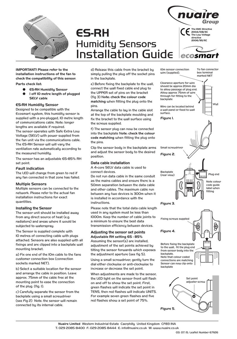
NuAire MRXBOX95-PIR Instruction Manual

NuAire

NuAire MRXBOX95-PIR Instruction Manual

NuAire NU-5810 User manual

NuAire

NuAire NU-5810 User manual

NuAire 1 Series User manual

NuAire

NuAire 1 Series User manual

NuAire 7 Series User manual

NuAire

NuAire 7 Series User manual

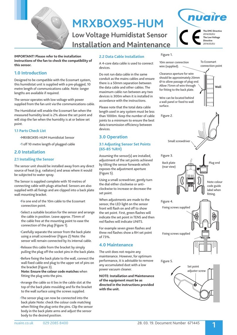
NuAire MRXBOX95-HUM Instruction Manual

NuAire

NuAire MRXBOX95-HUM Instruction Manual

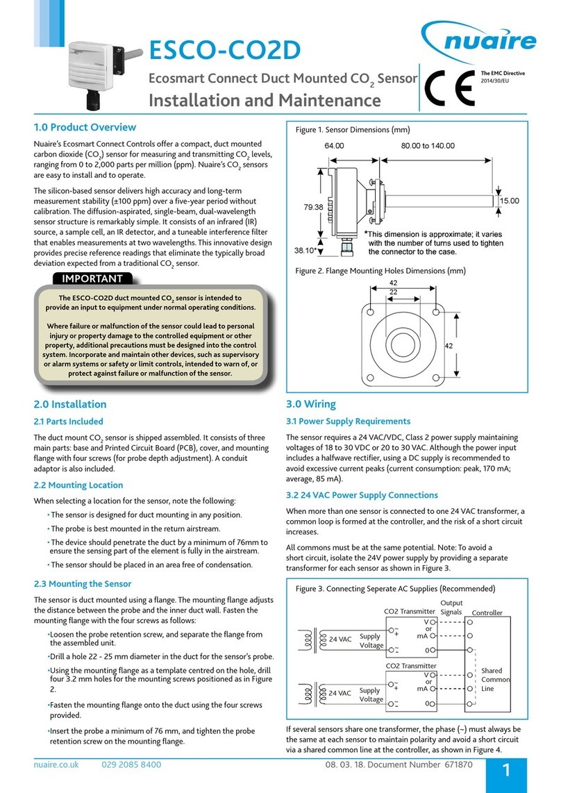
NuAire ESCO-CO2D User manual

NuAire

NuAire ESCO-CO2D User manual

NuAire Ecosmart Connect ESCO-CO2D Instruction Manual

NuAire

NuAire Ecosmart Connect ESCO-CO2D Instruction Manual

NuAire NU 4500 User manual

NuAire

NuAire NU 4500 User manual

NuAire 5 Series User manual

NuAire

NuAire 5 Series User manual

NuAire NU-8625 User manual

NuAire

NuAire NU-8625 User manual

NuAire NU-5500 User manual

NuAire

NuAire NU-5500 User manual

NuAire CM-XBOX-INLINE Instruction Manual

NuAire

NuAire CM-XBOX-INLINE Instruction Manual

NuAire DRI-ECO-RH User manual

NuAire

NuAire DRI-ECO-RH User manual

NuAire NU-5710 User manual

NuAire

NuAire NU-5710 User manual

NuAire ES-TEMP2 User manual

NuAire

NuAire ES-TEMP2 User manual

NuAire NU-5510 User manual

NuAire

NuAire NU-5510 User manual

NuAire 12 Series User manual

NuAire

NuAire 12 Series User manual

NuAire NU-8600 User manual

NuAire

NuAire NU-8600 User manual

NuAire ES-PIR2 User manual

NuAire

NuAire ES-PIR2 User manual

NuAire 3 Series User manual

NuAire

NuAire 3 Series User manual

NuAire NU-1000 User manual

NuAire

NuAire NU-1000 User manual

NuAire ES-RH User manual

NuAire

NuAire ES-RH User manual

Popular Accessories manuals by other brands

SICK GTE6 Series operating instructions

SICK

SICK GTE6 Series operating instructions

clare CVP-B3DB50-ODIW Installation and user guide

clare

clare CVP-B3DB50-ODIW Installation and user guide

Vernier Go Direct Thermocouple manual

Vernier

Vernier Go Direct Thermocouple manual

Contherm Cat 1050 instruction manual

Contherm

Contherm Cat 1050 instruction manual

PCB Piezotronics 208C04 Installation and operating manual

PCB Piezotronics

PCB Piezotronics 208C04 Installation and operating manual

Endress+Hauser Indumax CLS54 operating instructions

Endress+Hauser

Endress+Hauser Indumax CLS54 operating instructions

Maxxair NXMLRD Assembly instructions

Maxxair

Maxxair NXMLRD Assembly instructions

Craftsman 315.175320 Operator's manual

Craftsman

Craftsman 315.175320 Operator's manual

Leviton DMX-512 installation guide

Leviton

Leviton DMX-512 installation guide

Waeco ColdMachine 54 operating manual

Waeco

Waeco ColdMachine 54 operating manual

StarTech.com ST128HD20 quick start guide

StarTech.com

StarTech.com ST128HD20 quick start guide

Delphi SA10252 - SKYFi 3 Standard Live Wearable user guide

Delphi

Delphi SA10252 - SKYFi 3 Standard Live Wearable user guide

Dsoon NV5000 manual

Dsoon

Dsoon NV5000 manual

turck LUS211 Series Instructions for use

turck

turck LUS211 Series Instructions for use

INSTEON TriggerLinc 2843-2 owner's manual

INSTEON

INSTEON TriggerLinc 2843-2 owner's manual

Panasonic MA2SP01 Specification sheet

Panasonic

Panasonic MA2SP01 Specification sheet

Endress+Hauser Oxymax H COS21D operating instructions

Endress+Hauser

Endress+Hauser Oxymax H COS21D operating instructions

BAC Nexus quick start guide

BAC

BAC Nexus quick start guide

manuals.online logo
manuals.online logoBrands
  • About & Mission
  • Contact us
  • Privacy Policy
  • Terms and Conditions

Copyright 2025 Manuals.Online. All Rights Reserved.