manuals.online logo
Brands
  1. Home
  2. •
  3. Brands
  4. •
  5. NuAire
  6. •
  7. Accessories
  8. •
  9. NuAire ESCO-CO2D User manual

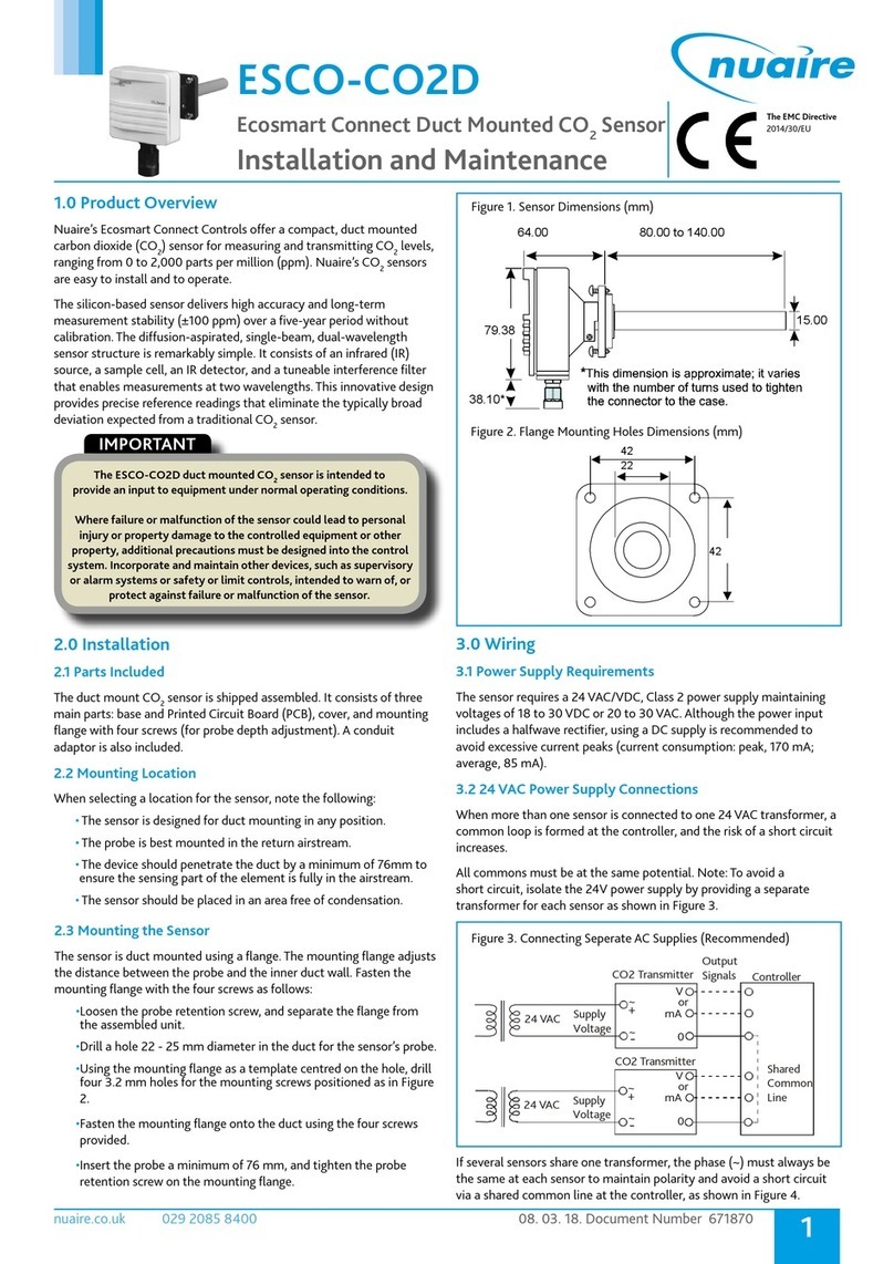
NuAire ESCO-CO2D User manual

16. 04. 21. Document Number 671635 1
Nuaire | Western Industrial Estate | Caerphilly | CF83 1NA | nuaire.co.uk
ESCO-CO2D
Ecosmart Connect Duct Mounted CO2Sensor
Installation Manual
1.0 SAFETY INFORMATION
• The provision of the electrical supply and the connection of the unit to the mains must be
carried out by a qualified electrician.
1.1 Hazard Symbols
GENERAL WARNING
Signifies a general warning regarding hazard specified by supplementary information.
REFER TO INSTRUCTION MANUAL
Read and understand the installation and maintenance manual before installing,
operating or maintaining this product.
1.2 Important Information
This manual contains important information on the safe and
appropriate assembly, transport, commissioning, operation,
maintenance, disassembly and simple troubleshooting of the product.
While the product has been manufactured according to the accepted
rules of current technology, there is still a danger of personal injury or
damage to equipment if the following general safety instructions and
the warnings contained in these instructions are not complied with.
•Read these instructions completely and thoroughly before
working with the product.
•Keep these instructions in a location where they are accessible
to all users at all times.
•Always include the operating instructions when you pass the
product on to third parties.
1.3 Personal Protective Equipment
The following minimum Personal Protective Equipment (PPE) is
recommended when interacting with Nuaire product:
•Protective Steel Toed Shoes - when handling heavy objects.
•Full Finger Gloves (Marigold PU800 or equivalent) - when
handling sheet metal components.
•Semi Fingerless Gloves (Marigold PU3000 3DO or equivalent)
- when conducting light work on the unit requiring tactile
dexterity.
•Safety Glasses - when conducting any cleaning/cutting operation
or exchanging filters.
•Reusable Half Mask Respirators - when replacing filters which
have been in contact with normal room or environmental air.
Nuaire would always recommend a site specific risk assessment by a
competent person to determine if any additional PPE is required.
2.0 INTRODUCTION
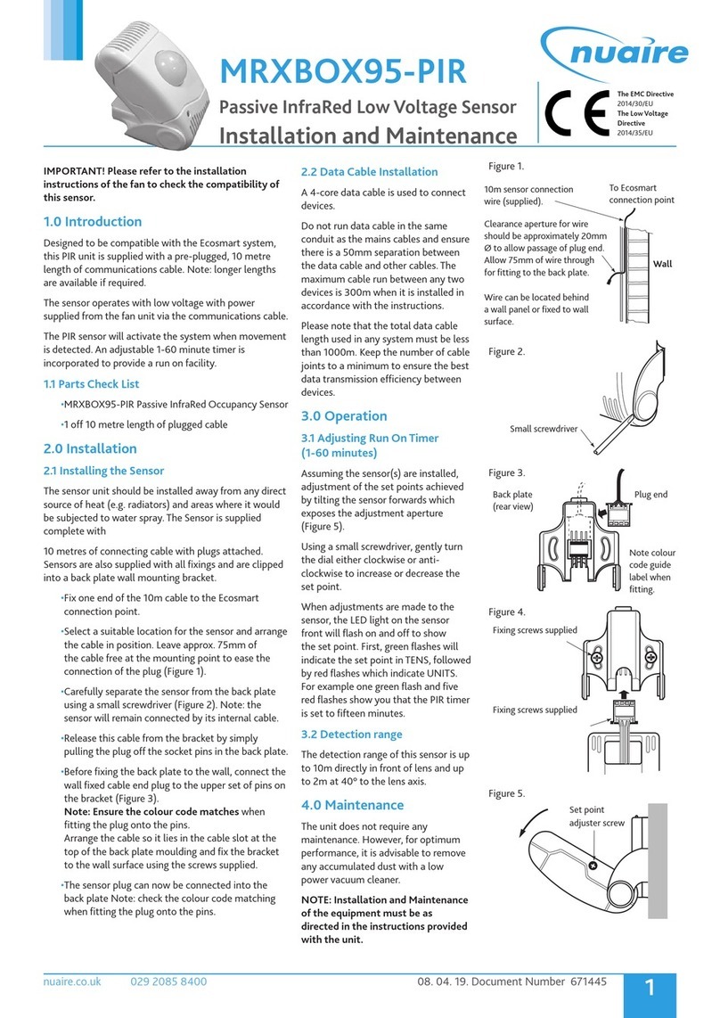
Nuaire’s Ecosmart Connect Controls offer a compact, duct mounted
carbon dioxide (CO2) sensor for measuring and transmitting CO2levels,
ranging from 0 to 2,000 parts per million (ppm). Nuaire’s CO2sensors
are easy to install and to operate.
The silicon-based sensor delivers high accuracy and long-term
measurement stability (±100 ppm) over a five-year period without
calibration. The diffusion-aspirated, single-beam, dual-wavelength
sensor structure is remarkably simple. It consists of an infrared (IR)
source, a sample cell, an IR detector, and a tuneable interference filter
that enables measurements at two wavelengths. This innovative design
provides precise reference readings that eliminate the typically broad
deviation expected from a traditional CO2sensor.
The ESCO-CO2D duct mounted CO2sensor is intended to
provide an input to equipment under normal operating conditions.
Where failure or malfunction of the sensor could lead to personal injury or
property damage to the controlled equipment or other
property, additional precautions must be designed into the control system.
Incorporate and maintain other devices, such as supervisory or alarm
systems or safety or limit controls, intended to warn of, or protect against
failure or malfunction of the sensor.
2.1 MECHANICAL INSTALLATION
2.2 Parts Included
The duct mount CO2sensor is shipped assembled. It consists of three
main parts: base and Printed Circuit Board (PCB), cover, and mounting
flange with four screws (for probe depth adjustment). A conduit
adaptor is also included.
2.3 Mounting Location
When selecting a location for the sensor, note the following:
•The sensor is designed for duct mounting in any position.
•The probe is best mounted in the return air stream.
•The device should penetrate the duct by a minimum of 76mm to
ensure the sensing part of the element is fully in the air stream.
•The sensor should be placed in an area free of condensation.
16. 04. 21. Document Number 671635 2
Nuaire | Western Industrial Estate | Caerphilly | CF83 1NA | nuaire.co.uk
ESCO-CO2D
Installation Manual
2.4 Mounting the Sensor
The sensor is duct mounted using a flange. The mounting flange adjusts
the distance between the probe and the inner duct wall. Fasten the
mounting flange with the four screws as follows:
•Loosen the probe retention screw, and separate the flange from
the assembled unit.
•Drill a hole 22 - 25 mm diameter in the duct for the sensor’s probe.
•Using the mounting flange as a template centred on the hole, drill
four 3.2 mm holes for the mounting screws positioned as in Figure
1.
•Fasten the mounting flange onto the duct using the four screws
provided.
•Insert the probe a minimum of 76 mm, and tighten the probe
retention screw on the mounting flange.
1 Dimensions (mm)
3.0 ELECTRICAL INSTALLATION
3.1 Power Supply Requirements
The sensor requires a 24 VAC/VDC, Class 2 power supply maintaining
voltages of 18 to 30 VDC or 20 to 30 VAC.
3.2 24 VAC Power Supply Connections
When more than one sensor is connected to one 24 VAC transformer, a
common loop is formed at the controller, and the risk of a short circuit
increases.
All commons must be at the same potential.
To avoid a short circuit, isolate the 24V power supply by providing
a separate transformer for each sensor as shown in Figure 2.
2 Connecting Separate AC Supplies (Recommended)
~
+
~
-
0
~
+
~
-
Shared
Common
Line
24 VAC Supply
Voltage
CO2 Transmitter
24 VAC Supply
Voltage
Output
Signals
CO2 Transmitter Controller
V
0
mA
or
V
mA
or
If several sensors share one transformer, the phase (~) must always be
the same at each sensor to maintain polarity and avoid a short circuit
via a shared common line at the controller, as shown in Figure 3.
.
0
Shared
Common
Line
Supply
Voltage
24 VAC
CO2 Sensor
Supply
Voltage
Output
Signals
CO2 Sensor Controller
~
+
~
-
~
+
~
-
V
0
mA
or
V
mA
or
3 Connecting One AC Supply to Several Sensors (Not
Recommended)
3.3 Wiring the PCB
To wire the PCB’s input and output connections:
•Open the sensor cover.
•Insert the wire carefully through the conduit adapter and then strip
6.35 mm of the wire insulation to prepare the wire for connection
to the terminal block.
•Connect the 24V supply between the UB+ and GND terminals as
shown in Figure 4.
•Connect the common wire to the GND terminal.
•Connect the other wire to AOU1 terminal (for voltage output).
4 Sensor PCB
CO2 - 0..10 V
15..35 V = | 19..29 V ~
4.0 SENSOR CALIBRATION
Nuaire’s carbon dioxide (CO2) sensors come from the factory calibrated
for the following:
•Output signal (0 to 10V) proportional to CO2 concentration (0 to
2,000 parts per million [ppm]).
•Altitude range of 0 to 600m above sea level without
compensation.
•Default relay output trigger point of 1,000 ppm.
5.0 TROUBLESHOOTING
The sensor is not field repairable.
In the event the unit is not functioning properly, use the following
checklist to identify the symptoms and determine a solution.
•Verify that all wiring is correct.
•Verify that the power supply voltage level is 20 to 30 VAC or 18 to
30 VDC.
16. 04. 21. Document Number 671635 3
Nuaire | Western Industrial Estate | Caerphilly | CF83 1NA | nuaire.co.uk
ESCO-CO2D
Installation Manual
6.0 TECHNICAL SPECIFICATIONS
ESCO-CO2D Ecosmart Connect Duct Mounted CO2Sensor
Product ESCO-CO2D Duct Mounted CO2 Sensor
Measuring Range 0 to 2,000 ppm CO2
Accuracy at 21°C < ±[50 ppm CO2 + 3.0% of reading] (includes manufacturing deviation and drift). All accuracy
specifications reflect testing the transmitters using high-grade, certified gases. Transmitters are
intended for an altitude range of 0 to 600 m above sea level without compensation.
Operating Temperature Range 0 to 50°C
Storage Temperature Range -20 to 70°C
Humidity Range 0 to 85% RH (non-condensing)
Transmitter Output Signal CO2 Jumper Selectable: 0 to 10 VDC (Default)
Maximum Output Voltage: 12.5V
Recommended External Load Current Output: Maximum 500 ohms Load Resistance
Voltage Output: Minimum 10k ohms Load Resistance
Power Supply Range 15..35 V = or 19..29 V ~ SELV
Power Consumption max. 2.3W; 4.3VA
Air Speed min. 0.3m/s, max. 12m/s
Duct Probe Material Duct Probe Meets Plenum Rating Requirements of UL 1995, Heating and Cooling Equipment
Housing Material ABS Plastic
Shipping Weight 0.14 Kg
The performance specifications are nominal and conform to acceptable industry standards.
7.0 WARRANTY
The 5 year warranty starts from the day of delivery and includes parts
and labour for the first year. The remaining 4 years covers replacement
parts only.
The labour element of the warranty is subject to full, free and safe
access to the equipment as recommended by CDM regulations.
This warranty is void if the equipment is modified without
authorisation, is incorrectly applied, misused, disassembled, or not
installed, commissioned and maintained in accordance with the details
contained in this manual and general good practice.
The product warranty applies to the UK mainland and in accordance
with Clause 14 of our Conditions of Sale. Customers purchasing from
outside of the UK should contact Nuaire International Sales office for
further details.
8.0 END-OF-LIFE AND RECYCLING
Where possible Nuaire use components which can be largely recycled
when the product reaches its end-of-life:
•Fans, motors, controls, actuators, cabling and other electrical
components can be segregated into WEEE recycling streams.
•Sheet metal parts, aluminium extrusion, heating/cooling coils and
other metallic items can be segregated and fully recycled.
•Cardboard packaging, wood, used filters and other paper
components can be largely recycled or fully processed in energy
from waste centres.
•Remaining items can be further segregated for energy from waste
centres or, as a last resort, sent to landfill. Please call After Sales
Support for further information on items not listed above.
Ensure that Nuaire product is made safe from any electrical / water
/ refrigerant supplies before dismantling commences. This work
should only be undertaken by a qualified person in accordance with
local authority regulations and guidelines, taking into account all
site based risks.
9.0 AFTER SALES AND REPLACEMENT PARTS
For technical assistance or further product information, including spare
parts and replacement components, please contact the After Sales
Department.
If ordering spares please quote the serial number of the unit together
with the part number, if the part number is not known please give a full
description of the part required. The serial number will be found on the
identification plate attached to the unit casing.
Telephone 02920 858 400
aftersales@nuaire.co.uk
Technical or commercial considerations may, from time to time,
make it necessary to alter the design, performance and dimensions
of equipment and the right is reserved to make such changes without
prior notice.

Other NuAire Accessories manuals

NuAire ES-PIR2 User manual

NuAire

NuAire ES-PIR2 User manual

NuAire ES-TEMP2 User manual

NuAire

NuAire ES-TEMP2 User manual

NuAire DRI-ECO-CO2 User manual

NuAire

NuAire DRI-ECO-CO2 User manual

NuAire NU 4500 User manual

NuAire

NuAire NU 4500 User manual

NuAire ES-RH User manual

NuAire

NuAire ES-RH User manual

NuAire NU-1000 User manual

NuAire

NuAire NU-1000 User manual

NuAire CM-XBOX-INLINE Instruction Manual

NuAire

NuAire CM-XBOX-INLINE Instruction Manual

NuAire MRXBOX95-HUM Instruction Manual

NuAire

NuAire MRXBOX95-HUM Instruction Manual

NuAire NU-5500 User manual

NuAire

NuAire NU-5500 User manual

NuAire NU-5810 User manual

NuAire

NuAire NU-5810 User manual

NuAire 5 Series User manual

NuAire

NuAire 5 Series User manual

NuAire DRI-ECO-RH User manual

NuAire

NuAire DRI-ECO-RH User manual

NuAire NU-5510 User manual

NuAire

NuAire NU-5510 User manual

NuAire NU-8625 User manual

NuAire

NuAire NU-8625 User manual

NuAire 3 Series User manual

NuAire

NuAire 3 Series User manual

NuAire Ecosmart Connect ESCO-CO2D Instruction Manual

NuAire

NuAire Ecosmart Connect ESCO-CO2D Instruction Manual

NuAire NU-5710 User manual

NuAire

NuAire NU-5710 User manual

NuAire 1 Series User manual

NuAire

NuAire 1 Series User manual

NuAire 7 Series User manual

NuAire

NuAire 7 Series User manual

NuAire MRXBOX95-PIR Instruction Manual

NuAire

NuAire MRXBOX95-PIR Instruction Manual

NuAire NU-8600 User manual

NuAire

NuAire NU-8600 User manual

NuAire 12 Series User manual

NuAire

NuAire 12 Series User manual

Popular Accessories manuals by other brands

technotrans termotek P70100-24495 Original instruction manual

technotrans

technotrans termotek P70100-24495 Original instruction manual

Hudora 76219 INSTRUCTIONS ON USE

Hudora

Hudora 76219 INSTRUCTIONS ON USE

Larson Electronics ATEX-EXP-DNS-400W-M20-HV instruction manual

Larson Electronics

Larson Electronics ATEX-EXP-DNS-400W-M20-HV instruction manual

Nibe RTS 40 Installer manual

Nibe

Nibe RTS 40 Installer manual

Skope HB80-2 user manual

Skope

Skope HB80-2 user manual

EVE door & window 20EAL9901 Get started

EVE

EVE door & window 20EAL9901 Get started

Fiamma ADVANCED F45s Installation and usage instructions

Fiamma

Fiamma ADVANCED F45s Installation and usage instructions

GeoSIG VE-3x Series Installation and operation manual

GeoSIG

GeoSIG VE-3x Series Installation and operation manual

Klimasan R600a Service manual

Klimasan

Klimasan R600a Service manual

Leviton OSSMD-FT install guide

Leviton

Leviton OSSMD-FT install guide

Craftsman 31293 Operator's manual

Craftsman

Craftsman 31293 Operator's manual

TP-Link HS103 user guide

TP-Link

TP-Link HS103 user guide

ALTAI A8n Series installation guide

ALTAI

ALTAI A8n Series installation guide

ORION TELESCOPES & BINOCULARS Stratus 08244d instruction manual

ORION TELESCOPES & BINOCULARS

ORION TELESCOPES & BINOCULARS Stratus 08244d instruction manual

ROSE DISPLAYS FISH CLIP instruction sheet

ROSE DISPLAYS

ROSE DISPLAYS FISH CLIP instruction sheet

Gaius GL-1028-A-2 manual

Gaius

Gaius GL-1028-A-2 manual

Viking SL-2 product manual

Viking

Viking SL-2 product manual

IFM Electronic Efector 200 operating instructions

IFM Electronic

IFM Electronic Efector 200 operating instructions

manuals.online logo
manuals.online logoBrands
  • About & Mission
  • Contact us
  • Privacy Policy
  • Terms and Conditions

Copyright 2025 Manuals.Online. All Rights Reserved.