manuals.online logo
Brands
  1. Home
  2. •
  3. Brands
  4. •
  5. NuAire
  6. •
  7. Accessories
  8. •
  9. NuAire Ecosmart Connect ESCO-CO2D Instruction Manual

NuAire Ecosmart Connect ESCO-CO2D Instruction Manual

1
nuaire.co.uk 029 2085 8400 08. 03. 18. Document Number 671870
The EMC Directive
2014/30/EU
ESCO-CO2D
Ecosmart Connect Duct Mounted CO2Sensor
Installation and Maintenance
1.0 Product Overview
Nuaire’s Ecosmart Connect Controls offer a compact, duct mounted
carbon dioxide (CO2) sensor for measuring and transmitting CO2levels,
ranging from 0 to 2,000 parts per million (ppm). Nuaire’s CO2sensors
are easy to install and to operate.
The silicon-based sensor delivers high accuracy and long-term
measurement stability (±100 ppm) over a five-year period without
calibration. The diffusion-aspirated, single-beam, dual-wavelength
sensor structure is remarkably simple. It consists of an infrared (IR)
source, a sample cell, an IR detector, and a tuneable interference filter
that enables measurements at two wavelengths. This innovative design
provides precise reference readings that eliminate the typically broad
deviation expected from a traditional CO2sensor.
2.0 Installation
2.1 Parts Included
The duct mount CO2sensor is shipped assembled. It consists of three
main parts: base and Printed Circuit Board (PCB), cover, and mounting
flange with four screws (for probe depth adjustment). A conduit
adaptor is also included.
2.2 Mounting Location
When selecting a location for the sensor, note the following:
•The sensor is designed for duct mounting in any position.
•The probe is best mounted in the return airstream.
•The device should penetrate the duct by a minimum of 76mm to
ensure the sensing part of the element is fully in the airstream.
•The sensor should be placed in an area free of condensation.
IMPORTANT
The ESCO-CO2D duct mounted CO2sensor is intended to
provide an input to equipment under normal operating conditions.
Where failure or malfunction of the sensor could lead to personal
injury or property damage to the controlled equipment or other
property, additional precautions must be designed into the control
system. Incorporate and maintain other devices, such as supervisory
or alarm systems or safety or limit controls, intended to warn of, or
protect against failure or malfunction of the sensor.
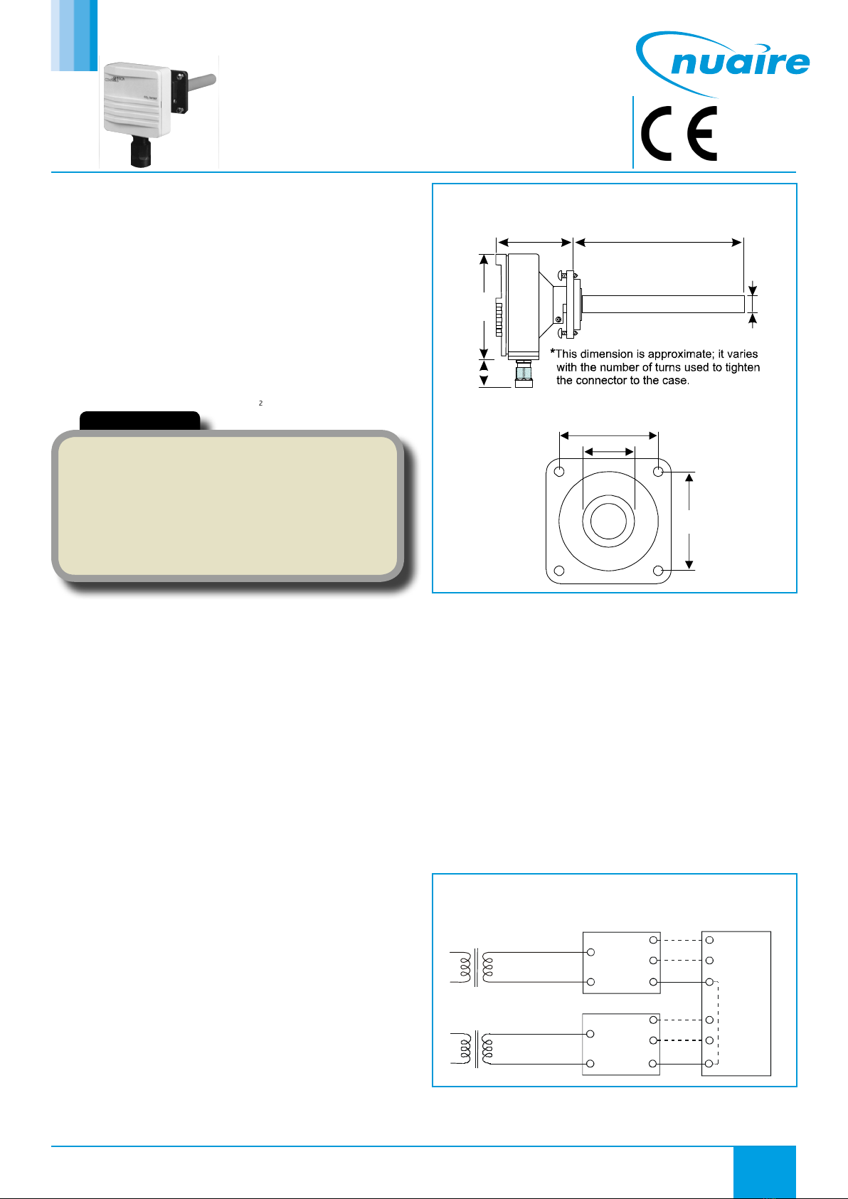
15.00
80.00 to 140.00
38.10*
64.00
79.38
Figure 1. Sensor Dimensions (mm)
2.3 Mounting the Sensor
The sensor is duct mounted using a flange. The mounting flange adjusts
the distance between the probe and the inner duct wall. Fasten the
mounting flange with the four screws as follows:
•Loosen the probe retention screw, and separate the flange from
the assembled unit.
•Drill a hole 22 - 25 mm diameter in the duct for the sensor’s probe.
•Using the mounting flange as a template centred on the hole, drill
four 3.2 mm holes for the mounting screws positioned as in Figure
2.
•Fasten the mounting flange onto the duct using the four screws
provided.
•Insert the probe a minimum of 76 mm, and tighten the probe
retention screw on the mounting flange.
3.0 Wiring
3.1 Power Supply Requirements
The sensor requires a 24 VAC/VDC, Class 2 power supply maintaining
voltages of 18 to 30 VDC or 20 to 30 VAC. Although the power input
includes a halfwave rectifier, using a DC supply is recommended to
avoid excessive current peaks (current consumption: peak, 170 mA;
average, 85 mA).
3.2 24 VAC Power Supply Connections
When more than one sensor is connected to one 24 VAC transformer, a
common loop is formed at the controller, and the risk of a short circuit
increases.
All commons must be at the same potential. Note: To avoid a
short circuit, isolate the 24V power supply by providing a separate
transformer for each sensor as shown in Figure 3.
~
+
~
-
0
~
+
~
-
Shared
Common
Line
24 VAC Supply
Voltage
CO2 Transmitter
24 VAC Supply
Voltage
Output
Signals
CO2 Transmitter Controller
V
0
mA
or
V
mA
or
Figure 3. Connecting Seperate AC Supplies (Recommended)
If several sensors share one transformer, the phase (~) must always be
the same at each sensor to maintain polarity and avoid a short circuit
via a shared common line at the controller, as shown in Figure 4.
42
22
42
Figure 2. Flange Mounting Holes Dimensions (mm)
2
nuaire.co.uk 029 2085 8400 08. 03. 18. Document Number 671870
Installation and Maintenance Ecosmart Connect Duct Mounted CO2Sensor
0
Shared
Common
Line
Supply
Voltage
24 VAC
CO2 Sensor
Supply
Voltage
Output
Signals
CO2 Sensor Controller
~
+
~
-
~
+
~
-
V
0
mA
or
V
mA
or
mAV0
—+
X3 V7 V10
0/4mA
X7X6
X5
SERIAL COM
Figure 4. Connecting One AC Supply to Several Sensors (Not
Recommended)
Figure 6. Sensor PCB.
3.3 Connecting the Conduit Adaptor
•Align the nut with the opening inside the enclosure, and hold it in
place.
•Insert the adaptor body into the sensor conduit opening.
•Manually tighten the adaptor into the nut, turning in a clockwise
direction (see Figure 5).
•Insert the wires through the conduit adaptor body opening.
•Tighten the adaptor onto the adaptor body by turning the adaptor
in a clockwise direction.
IMPORTANT
Do not overtighten the conduit adaptor, doing so could cause damage
to or displacement of the PCB.
Nut
Adaptor Body
Adaptor
Figure 5. Inserting the Conduit Adaptor.
3.4 Wiring the PCB
To wire the PCB’s input and output connections:
•Open the sensor cover.
•Insert the wire carefully through the conduit adapter and then strip
6.35 mm of the wire insulation to prepare the wire for connection
to the terminal block.
•Connect the 24V supply between the positive (+) and negative (-)
terminals as shown in Figure 6.
•Connect the common wire to Terminal 0.
•Connect the other wire to Terminal V (for voltage output).
4.0 Sensor Calibration
Nuaire’s carbon dioxide (CO2) sensors come from the factory calibrated
for the following:
•Output signal (0 to 10V) proportional to CO2 concentration (0 to
2,000 parts per million [ppm]).
•Altitude range of 0 to 600m above sea level without
compensation.
•Default relay output trigger point of 1,000 ppm.
5.0 Troubleshooting
The sensor is not field repairable.
In the event the unit is not functioning properly, use the following
checklist to identify the symptoms and determine a solution.
•Verify that all wiring is correct.
•Verify that the power supply voltage level is 20 to 30 VAC or 18 to
30 VDC.
Note: The diagnostic Light-Emitting Diodes (LEDs) shown in the lower
right-hand corner of Figure 6 indicate operational status:
•V7 lights up if the self-diagnostics procedure detects an
abnormality.
•V10 pulses to indicate that the device is operational.
If the sensor will not operate after completing these steps, replace the
unit.
3
nuaire.co.uk 029 2085 8400 08. 03. 18. Document Number 671870
Installation and Maintenance Ecosmart Connect Duct Mounted CO2Sensor
8.0 After Sales
For technical assistance or further product information, please contact
the After Sales Department.
Telephone 02920 858 400
aftersales@nuaire.co.uk
LCD Browser Page BACnet Object
Product ESCO-CO2D Duct Mounted CO2 Sensor
Measuring Range 0 to 2,000 ppm CO2
Accuracy at 25°C < ±[30 ppm CO2 + 2.0% of reading] (includes manufacturing deviation and drift). All accuracy
specifications reflect testing the transmitters using high-grade, certified gases. Transmitters are
intended for an altitude range of 0 to 600 m above sea level without compensation.
Non-Linearity < 0.5% of Full Scale
Temperature Dependence of Output < 0.1% of Full Scale/C°
Long-Term Stability < ±5.0% of Full Scale/5 Years
Response Time (0 to 63%) 1 Minute
Operating Temperature Range -5 to 45°C
Storage Temperature Range -20 to 70°C
Humidity Range 0 to 85% RH (non-condensing)
Transmitter Output Signal CO2 Jumper Selectable: 0 to 10 VDC (Default)
Maximum Output Voltage: 12.5V
Relay Output (Optional) Maximum 30V, 0.5A, Class 2
Recommended External Load Current Output: Maximum 500 ohms Load Resistance
Voltage Output: Minimum 1,000 ohms Load Resistance
Power Supply Range 20 to 30 VAC (18 to 30 VDC), Class 2
Power Consumption < 2.5 W Average, 4.1 VA
Warm-up Time < 5 Minutes
Air Flow Range 0 to 2,286 m/Minute
Duct Probe Material Duct Probe Meets Plenum Rating Requirements of UL 1995, Heating and Cooling Equipment
Housing Material ABS Plastic
Dimensions (H x W x D) 80 x 81 x 204 (mm)
Shipping Weight 0.14 Kg
6.0 Technical Data
7.0 Warranty
The 5 year warranty starts from the day of delivery and includes parts
and labour for the first year. The remaining 4 years covers replacement
parts only.
The labour element of the warranty is subject to full, free and safe
access to the equipment as recommended by CDM regulations.
This warranty is void if the equipment is modified without
authorisation, is incorrectly applied, misused, disassembled, or not
installed, commissioned and maintained in accordance with the details
contained in this manual and general good practice.
The product warranty applies to the UK mainland and in accordance
with Clause 14 of our Conditions of Sale. Customers purchasing from
outside of the UK should contact Nuaire International Sales office for
further details.
The performance specifications are nominal and conform to acceptable industry standards.

Other NuAire Accessories manuals

NuAire DRI-ECO-CO2 User manual

NuAire

NuAire DRI-ECO-CO2 User manual

NuAire 3 Series User manual

NuAire

NuAire 3 Series User manual

NuAire ES-RH User manual

NuAire

NuAire ES-RH User manual

NuAire NU 4500 User manual

NuAire

NuAire NU 4500 User manual

NuAire ES-TEMP2 User manual

NuAire

NuAire ES-TEMP2 User manual

NuAire MRXBOX95-PIR Instruction Manual

NuAire

NuAire MRXBOX95-PIR Instruction Manual

NuAire DRI-ECO-RH User manual

NuAire

NuAire DRI-ECO-RH User manual

NuAire NU-5500 User manual

NuAire

NuAire NU-5500 User manual

NuAire NU-8600 User manual

NuAire

NuAire NU-8600 User manual

NuAire 7 Series User manual

NuAire

NuAire 7 Series User manual

NuAire 5 Series User manual

NuAire

NuAire 5 Series User manual

NuAire ES-PIR2 User manual

NuAire

NuAire ES-PIR2 User manual

NuAire NU-8625 User manual

NuAire

NuAire NU-8625 User manual

NuAire NU-5510 User manual

NuAire

NuAire NU-5510 User manual

NuAire NU-5710 User manual

NuAire

NuAire NU-5710 User manual

NuAire ESCO-CO2D User manual

NuAire

NuAire ESCO-CO2D User manual

NuAire MRXBOX95-HUM Instruction Manual

NuAire

NuAire MRXBOX95-HUM Instruction Manual

NuAire 12 Series User manual

NuAire

NuAire 12 Series User manual

NuAire 1 Series User manual

NuAire

NuAire 1 Series User manual

NuAire NU-1000 User manual

NuAire

NuAire NU-1000 User manual

NuAire NU-5810 User manual

NuAire

NuAire NU-5810 User manual

NuAire CM-XBOX-INLINE Instruction Manual

NuAire

NuAire CM-XBOX-INLINE Instruction Manual

Popular Accessories manuals by other brands

GEM PBT-020-4 Specification sheet

GEM

GEM PBT-020-4 Specification sheet

Mitsubishi Electric KD Series user manual

Mitsubishi Electric

Mitsubishi Electric KD Series user manual

Honeywell FireLite SD355, FireLite SD355T Installation and maintenance instructions

Honeywell

Honeywell FireLite SD355, FireLite SD355T Installation and maintenance instructions

Zeta OPZ1ZT92 quick start guide

Zeta

Zeta OPZ1ZT92 quick start guide

Dometic ELITE SLIDE TOPPER Series Installation & operating instructions

Dometic

Dometic ELITE SLIDE TOPPER Series Installation & operating instructions

HENGBO HB-MC-1 user manual

HENGBO

HENGBO HB-MC-1 user manual

Stokke XPLORY X user guide

Stokke

Stokke XPLORY X user guide

Wenglor OEII403C0103 user manual

Wenglor

Wenglor OEII403C0103 user manual

Britax BOB Gear Travel Bag Instruction

Britax

Britax BOB Gear Travel Bag Instruction

Dell Active Pen PN556W user guide

Dell

Dell Active Pen PN556W user guide

ROSE DISPLAYS ANOQUICK ROUND WITH CABLE AND CRIMP SLEEVES instruction sheet

ROSE DISPLAYS

ROSE DISPLAYS ANOQUICK ROUND WITH CABLE AND CRIMP SLEEVES instruction sheet

Sontay GS-S-CO-W quick start guide

Sontay

Sontay GS-S-CO-W quick start guide

Pyxis LS-200 Quick start up guide

Pyxis

Pyxis LS-200 Quick start up guide

Dryve Designs Dryve 2600 user manual

Dryve Designs

Dryve Designs Dryve 2600 user manual

Novalynx 200-WS-23 user manual

Novalynx

Novalynx 200-WS-23 user manual

Mark 7 PrimerSense 1050 instruction manual

Mark 7

Mark 7 PrimerSense 1050 instruction manual

SunSetter OASIS Series installation instructions

SunSetter

SunSetter OASIS Series installation instructions

Symphony Diet 3D user manual

Symphony

Symphony Diet 3D user manual

manuals.online logo
manuals.online logoBrands
  • About & Mission
  • Contact us
  • Privacy Policy
  • Terms and Conditions

Copyright 2025 Manuals.Online. All Rights Reserved.