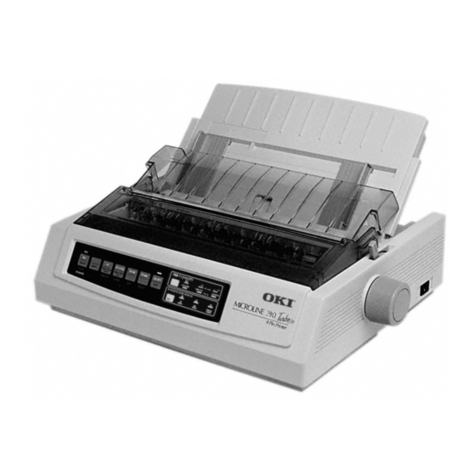
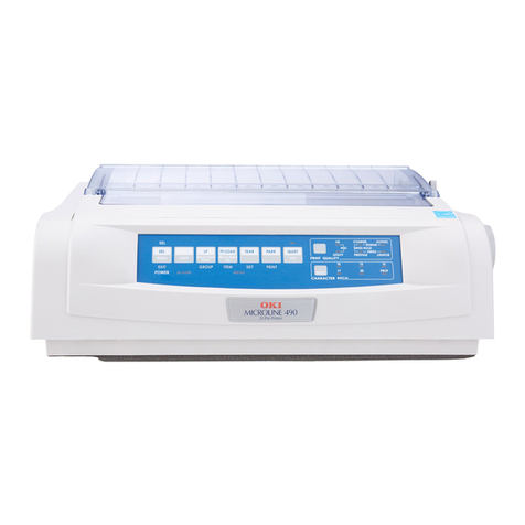
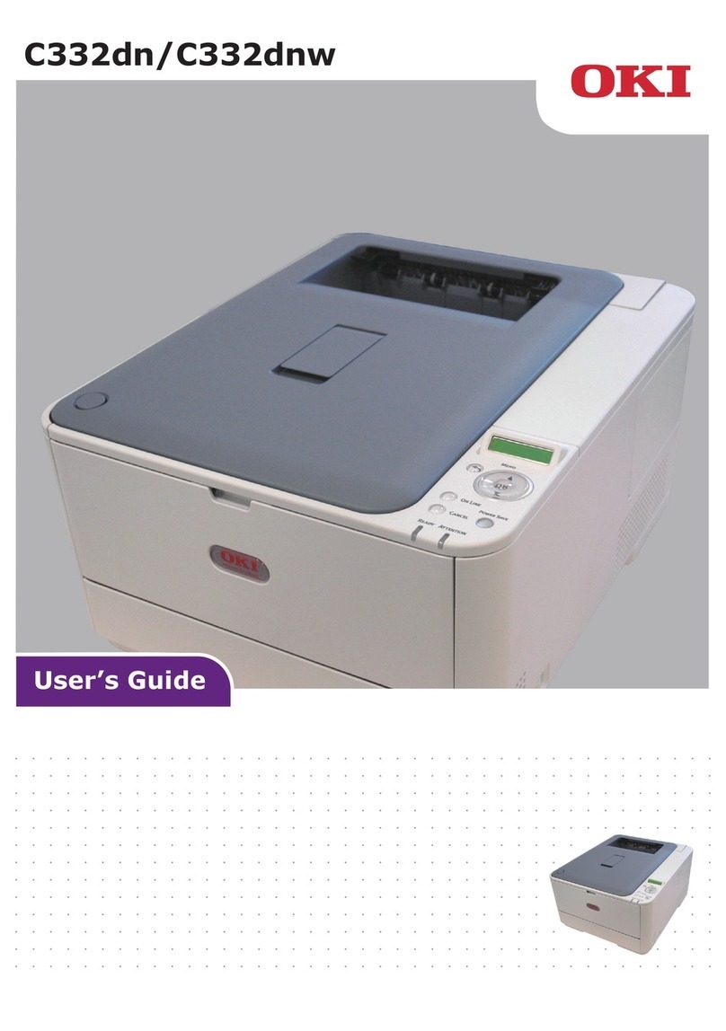
Oki C301 User manual

OEL
Maintenance Manual
C301/C321/C331/C511/C531
Revision 2
Rev Date Oki Data Corporation
1 2012-04-26
2 2012-06-29
Name
C301/C321/C331/C511/C531
Maintenance Manual
This document is “OKI DATA – CONFIDENTIAL”
Only persons and parties authorised by OKI DATA have
permissions to access this document.
This document should not be accessed by any parties
without the approval of OKI DATA.
Anyone who is found to be contradicting the above may be subject to legal action.

44951501TH Rev.2 ii /
Oki Data CONFIDENTIAL
Document Revision History
Rev.
No. Date Changed items Person in charge
No. Page Description of change
1 2012-04-26 Issue NME13
H. Enomoto
2 2012-06-29 Addition of EDT series NME13
H. Enomoto
Rev.
No. Date Changed items Person in charge
No. Page Description of change
Document Revision History

44951501TH Rev.2 iii /
Oki Data CONFIDENTIAL
This manual explains the maintenance methods for the C301dn, C321dn, C331dn, C511dn
and C531dn printers.
The manual has been prepared for use by the maintenance personnel. For how to operate
the C301dn/C321dn/C331dn/C511dn and C531dn printers, refer to the corresponding user’s
manual.
These printer names may be given as follows in this manual.
C301dn
C301
C321dn
C321
C331dn
C331
C511dn
C511
C531dn
C531
Note! •Thecontentsofthismanualaresubjecttochangeswithoutpriornotice.
•Despitethatexhaustiveeffortsweremadeinpreparingthemanualtomake
it accurate, it still may contain errors. Oki Data will not hold itself liable
for any damage that results or is claimed to have resulted from repairs,
adjustment, or modications of the printers conducted by the users using
this manual.
•ThepartsemployedintheC301dn,C321dn,C331dn,C511dn,andC531dn
printers are so delicate that they may be damaged if not treated properly.
Oki Data Corporation highly recommends that the maintenance of the
printers is undertaken by ODC's registered maintenance personnel.
•Workaftereliminatingstaticelectricity.
PREFACE
PREFACE

44951501TH Rev.2 iv /
Oki Data CONFIDENTIAL
CONTENTS
CONTENTS
1. CONFIGURATION..................................................................1-1
1.1 System configuration .........................................................................................1-2
1.2 Printer configuration ...........................................................................................1-3
1.3 Optional items ....................................................................................................1-4
1.4 Specifications .....................................................................................................1-5
1.5 Interface specifications .......................................................................................1-9
1.5.1 USB interface specifications ........................................................................1-9
1.5.1.1 USB interface overview.........................................................................1-9
1.5.1.2 USB interface connector and cable ......................................................1-9
1.5.1.3 USB interface signals ...........................................................................1-9
1.5.2 Network interface specifications ................................................................1-10
1.5.2.1 Network interface overview.................................................................1-10
1.5.2.2 Network interface connector and cable...............................................1-10
1.5.2.3 Network interface signals ...................................................................1-10
2. DESCRIPTION OF OPERATION ...........................................2-1
2.1 Electrophotographic process mechanism ..........................................................2-2
2.2 Printing process..................................................................................................2-6
3.INSTALLATION........................................................................3-1
3.1 Cautions, and do’s and don’ts.............................................................................3-2
3.2 Unpacking procedure .........................................................................................3-3
3.3. Printer installation instructions ..........................................................................3-4
3.4 List of components and accessories ..................................................................3-5
3.5 Assembly procedure ..........................................................................................3-6
3.5.1 Assembly of the printer main unit ................................................................3-6
3.5.2 Connection of the power cable ..................................................................3-10
3.5.3 Installation and recognition confirmation of an option ...............................3-12
3.6 Printing of MenuMap ........................................................................................3-21
3.7 Connection methods.........................................................................................3-22
3.8 Checking of paper used by the user .................................................................3-24
4.REPLACEMENT OF PARTS...................................................4-1
4.1 Notes on replacement of parts............................................................................4-2
4.2 Part replacement procedure ...............................................................................4-4
4.2.1 Belt unit.........................................................................................................4-4
4.2.2 Fuser unit......................................................................................................4-5
4.2.3 Left side cover ..............................................................................................4-5
4.2.4 Right side cover............................................................................................4-6
4.2.5 Face-up tray..................................................................................................4-6
4.2.6 Rear cover....................................................................................................4-7
4.2.7 LED assembly. and LED assembly springs ..................................................4-7
4.2.8 Image drum fan and ZHJ board....................................................................4-8
4.2.9 CU/PU PCB and low-voltage power supply..................................................4-8
4.2.10 Top cover assembly..................................................................................4-10
4.2.11 Top cover and LED head cable assembly.................................................4-10
4.2.12 Operator panel assembly..........................................................................4-11
4.2.13 Board IBB and LCD..................................................................................4-11
4.2.14 MPT assembly..........................................................................................4-12
4.2.15 Front fan, hopping motor, rear fan, image drum motor and
cover-open switch.....................................................................................4-13
4.2.16 High-voltage power supply board.............................................................4-14
4.2.17Guide-ejectionassembly,fuserconnectorassemblyand
color-registration assembly ......................................................................4-15
4.2.18 Frame-MPT assembly and feeder assembly...........................................4-16
4.2.19 Side-L assembly, side-R assembly and base assembly ⑦.....................4-17
4.2.20 Feed rollers...............................................................................................4-18
4.3 Locations to lubricate........................................................................................4-19

44951501TH Rev.2 v /
Oki Data CONFIDENTIAL CONTENTS
5. MAINTENANCE MENUS........................................................5-1
5.1 System Maintenance menu (for maintenance personnel)...................................5-2
5.2 Maintenance Utility..............................................................................................5-4
5.3 User maintenance menu functions .....................................................................5-6
5.3.1 Maintenance menu (for end-users)...............................................................5-6
5.3.2 Self-diagnostic mode....................................................................................5-7
5.3.3 Various types of printing on stand-alone basis...........................................5-24
5.3.4 Button functions at power-on......................................................................5-25
5.4 Setup after part replacement ............................................................................5-26
5.4.1 Notes on CU/PU board replacement..........................................................5-26
5.5Manualdensityadjustmentoperation ...............................................................5-28
5.6 Printer ADMIN MENU.......................................................................................5-29
6. PERIODIC MAINTENANCE ...................................................6-1
6.1 Cleaning..............................................................................................................6-2
6.2 LED lens array cleaning......................................................................................6-3
6.3 Pick-up roller cleaning.........................................................................................6-5
6.4 Pinter internal cleaning .......................................................................................6-6
7.TROUBLESHOOTING.............................................................7-1
7.1 Before troubleshooting........................................................................................7-2
7.2 Points to check before dealing with image troubles............................................7-2
7.3 Precautions for dealing with image troubles .......................................................7-2
7.4 Preparation for troubleshooting...........................................................................7-2
7.5 Troubleshooting procedure..................................................................................7-3
7.5.1 LCD messages list........................................................................................7-3
7.5.2 Preparation for troubleshooting ..................................................................7-24
7.5.3 Troubleshooting of image problems ...........................................................7-57
7.5.4 Network troubleshooting ............................................................................7-64
7.5.4.1 ConnectionerrorsoccurbyuseofaWebbrowser
(for C321/C331/C531) ....................................................................7-64
7.5.4.1.1 Has a certificate been created?...................................................7-65
7.5.4.1.2 Is the SSL/TLS setting set to ON?...............................................7-65
7.5.4.1.3ChecktheversionnumberoftheWebbrowser. ..........................7-66
7.5.4.2 Print operation is not possible (for C321/C331/C531) ........................7-67
7.5.4.2.1 Check the OS (Operating System)..............................................7-67
7.5.4.2.2 Has a printer been created?........................................................7-67
7.5.4.2.3 Is the IPP setting set to Enable? .................................................7-67
7.5.4.3 A certificate cannot be created. (for C321/C331/C531) ......................7-67
7.5.4.3.1 Not all the required entry fields are filled in.................................7-67
7.5.4.3.2 The printer is printing...................................................................7-68
7.5.4.4 A certificate cannot be installed. (for C321/C331/C531).................7-68
7.5.4.4.1 The printer IP address has been changed. .................................7-68
7.5.4.4.2 The network card has been initialized. ........................................7-68
7.5.4.4.3 A CSR has been deleted.............................................................7-68
7.5.4.4.4 Install an intermediate Certificate. ..............................................7-69
7.5.4.5 Other questions (for C321/C331/C531) .............................................7-70
7.5.4.5.1 Time required for creation of a certificate....................................7-70
7.5.4.5.2 Communication time when the encryption function is enabled....7-70
7.5.4.5.3 Can encrypted printing be performed without IPP?.....................7-70
7.5.4.5.4Whatwill happen if SSL/TLS is set to OFF after a certificate is
created (or installed)?..................................................................7-70
7.5.4.5.5 How to change the port number..................................................7-70
7.5.4.5.6 The error message “The security certificate was issued by a
company you have not chosen to trust.View the certificate to
determine whether you want to trust the certifying authority” is
displayed......................................................................................7-70
7.5.4.5.7 The error message “Name of security certificate is invalid or does
not match the site name” is displayed..........................................7-71
7.5.4.6 Restrictions when using Internet Explore 7 (for C321/C331/C531) .7-72
7.5.4.6.1WarningindicationwhenSSLisenabledforself-signed
certificates ...................................................................................7-72
7.6 Fuse check........................................................................................................7-73
8. CONNECTION DIAGRAMS ..................................................8-1
8.1 Resistance value checking .................................................................................8-2
8.2 Layout of parts ...................................................................................................8-5
8.3 Firmware revision numbers ..............................................................................8-19
8.3.1 ROM control numbers.................................................................................8-19
8.3.2 Checking and indication of the revision number ........................................8-20
8.3.3 Stamp of maintenance board indication ....................................................8-20
Oki Data CONFIDENTIAL
1.
CONFIGURATION
1.1 System configuration ...................................................................1-2
1.2 Printer configuration ....................................................................1-3
1.3 Optional items ..............................................................................1-4
1.4 Specifications ..............................................................................1-5
1.5 Interface specifications ................................................................1-9

44951501TH Rev.2 1-2 /
Oki Data CONFIDENTIAL 1. CONFIGURATION
㻻㻼㻣㻞㻠
㻼㻯㻮㻙㼀㻭㻳
㻔㼅㻕
㼅㻙㻵㻰
㻹㻙㻵㻰
㻯㻙㻵㻰
㻷㻙㻵㻰
㻼㻯㻮㻙㼀㻭㻳
㻔㻹㻕
㻼㻯㻮㻙㼀㻭㻳
㻔㻯㻕
㻼㻯㻮㻙㼀㻭㻳
㻔㻷㻕
㻼㻯㻮㻙㻻㻾㼆
㻔㻼㼃㻾㻌㼡㼚㼕㼠㻙㻴㼕㼓㼔㻌㼂㼛㼘㼠㼍㼓㼑㻕
㻰㻮㻙㼅
㻿㻮㻙㼅
㻰㻮㻙㻹
㻿㻮㻙㻹
㻰㻮㻙㻯
㻿㻮㻙㻯
㻯㻴㻙㻷
㻰㻮㻙㻷
㻿㻮㻙㻷
㻷㼀㻺㻾㻯㼀㻺㻾㻹㼀㻺㻾
㼅㼀㻺㻾
㻞㻠㻼
㻮㻱㻸㼀
㻼㻯㻮㻙㻿㻻㻼㻌㻔㻯㻟㻜㻝㻘㻌㻯㻡㻝㻝㻕㻌
㻼㻯㻮㻙㻯㻸㻽㻌㻔㻯㻟㻞㻝㻘㻌㻯㻟㻟㻝㻘㻌㻯㻡㻟㻝㻕
㼁㻿㻮
㻸㻭㻺
㻴㻻㻼
㻹㼛㼠㼛㼞
㻼㻯㻮㻙㻵㻮㻮
㻸㻱㻰㻝 㻸㻱㻰㻞
㻿㼃㻝㻿㼃㻞
㻠㻼
㻝㻞㻼
㻯㼛㼢㼑㼞㻻㼜㼑㼚
㻌㻿㼣㼕㼠㼏㼔
㻙㻌㻌㻌㻌㻌㻗
㻼㻯㻮㻙㼆㻴㻶
㼅㻴㻱㻭㻰
㻹㻴㻱㻭㻰
㻯㻴㻱㻭㻰
㻷㻴㻱㻭㻰
㻼㼔㼛㼠㼛㻌㻵㼚㼠㼑㼞㼞㼡㼜㼠㼑㼞
㻟㻼
㻼㼔㼛㼠㼛㻌㻵㼚㼠㼑㼞㼞㼡㼜㼠㼑㼞
㻟㻼
㻼㼔㼛㼠㼛㻌㻵㼚㼠㼑㼞㼞㼡㼜㼠㼑㼞
㻟㻼
㻿㼃㻟㻿㼃㻠
㻿㼃㻡㻿㼃㻢
㻼㼔㼛㼠㼛㻌㻵㼚㼠㼑㼞㼞㼡㼜㼠㼑㼞
㻟㻼
㼃㻾
㻵㻺
㻴㻻㻼
㻼㻱㻺㻰
㻯㼘㼡㼠㼏㼔
㻔㻾㻱㻳㻕
㻯㼘㼡㼠㼏㼔
㻔㻴㼛㼜㻕
㻼㼔㼛㼠㼛㻌㻵㼚㼠㼑㼞㼞㼡㼜㼠㼑㼞
㻟㻼
㻱㼄㻵㼀
㻾㻱㻭㻾㻌㻯㼛㼢㼑㼞 㻞㻼
㻴㼡㼙㼕㼐㼕㼠㼥㻌㼟㼑㼚㼟㼛㼞
㻼㼔㼛㼠㼛㻌㻵㼚㼠㼑㼞㼞㼡㼜㼠㼑㼞
㻟㻼
㻼㼔㼛㼠㼛㻌㻵㼚㼠㼑㼞㼞㼡㼜㼠㼑㼞
㻟㻼
㻰㼡㼜㻌㻾㼑㼍㼞
㻰㼡㼜㻌㻲㼞㼛㼚㼠
㻡㻼
㻰㼑㼚㼟㼕㼠㼥㻌㻿㼑㼚㼑㼛㼞
㻝㻢㻼
㻰㼞㼍㼣㼑㼞
㻯㼛㼚㼚㼑㼏㼠㼛㼞
㻠㻼
㻤㻼
㻝㻜㻼㻢㻼㻞㻼㻡㻼
㻟㻼
㻝㻞㻼
㻢㻼
㻠㻼
㻞㻼
㻞㻼
㻞㻠㻼
㻞㻼
㻠㻼
㻮㼑㼘㼠㻌㼀㼔㼑㼞㼙㼕㼟㼠㼛㼞
㻿㼔㼡㼠㼠㼑㼞
㻿㼛㼘㼑㼚㼛㼕㼐
㻡㻼
㻯㼛㼘㼛㼞㻾㼑㼓㻌㻿㼑㼚㼑㼛㼞
㻰㻯㻵㻰
㻹㼛㼠㼛㼞
㻥㻼
㻥㻼
㻥㻼
㻹㼛㼠㼛㼞㻙
㻲㻭㻺㻔㻼㼛㼣㼑㼞㻕
㻝㻢㻼
㻲㻲㻯㻜㻠
㻞㻜㻼
㻞㻜㻼
㻞㻜㻼
㻞㻜㻼
㻲㻲㻯㻜㻡
㻲㻲㻯㻜㻢
㻲㻲㻯㻜㻣
㻷㻌㻸㻱㻰㻌㻴㻱㻭㻰
㻯㻌㻸㻱㻰㻌㻴㻱㻭㻰
㻹㻌㻸㻱㻰㻌㻴㻱㻭㻰
㼅㻌㻸㻱㻰㻌㻴㻱㻭㻰
㻲㻳
㻲㼕㼘㼙㻙㻲㻳
㻲㻳
㻼㼃㻾㻌㼡㼚㼕㼠
㻙㻭㻯㻰㻯㻌㻿㼣㼕㼠㼏㼔㻌
㻲㼁㻿㻱㻾
㼘㼛㼣㼑㼞㻙㼠㼔
㼡㼜㼜㼑㼞㻙㼠㼔
㼒㼞㼍㼙㼑㻙㼠㼔
㼀㼔㼑㼞㼙㼛㼟㼠㼍㼠
㻥㻼
㻵㼚㼘㼑㼠㻭㻯㻻㼡㼠㼘㼑㼠
㻲㻳
㼟㼕㼐㼑㻙㼠㼔
㻠㻼
㻠㻼
㻝㻢㻼
㻡㻼
㻠㻼
㻡㻼
㻰㼞㼍㼣㼑㼞
㻯㼛㼚㼚㼑㼏㼠㼛㼞
㻟㻼㻔㻞㻕
㻮㼘㼍㼏㼗
㻤㻼
㻠㻼
㻠㻼
㻟㻼
㻤㻼 㻤㻼
㻰㻯
㻴㻱㻭㼀
㻹㼛㼠㼛㼞
㻤㻼
㻠㻼
㻮㼑㼘㼠
㻹㼛㼠㼛㼞
㻠㻼
㻯㼘㼡㼠㼏㼔
㻔㻰㼡㼜㻕
㻞㻼
㻼㻜㻝
㻼㻜㻡
㻼㻜㻢
㻼㻜㻣
㻼㻜㻤
㻼㻜㻥
㻼㻝㻜
㻼㻝㻞
㻼㻝㻟
㻼㻝㻠
㻼㻝㻡
㻼㻝㻢
㻼㻝㻤
㻲㻲㻯㻜㻝
㻲㻲㻯㻜㻞
㻲㻲㻯㻜㻟
㻭㻜㻞
㻭㻜㻟
㻭㻜㻠
㻭㻜㻡
㻭㻜㻢
㻭㻜㻝
㻟㻼
㻼㻝㻥
㻹㼛㼠㼛㼞㻙㻲㻭㻺㻔㻵㻰㻕
㻭㻜㻤
㻟㻼
㻮㼑㼘㼠㻌㻲㼡㼟㼑
㻲㻲㻯㻜㻤
㼀㼛㼚㼑㼞㻲㼡㼘㼘㻌㻿㼑㼚㼑㼛㼞
㻵㻰㻌㼁㻼㻰㻻㼃㻺
㻼㼔㼛㼠㼛㻌㻵㼚㼠㼑㼞㼞㼡㼜㼠㼑㼞
㻼㻯㻮㻙㻱㻻㻱
㻼㻯㻮㻙㻰㻻㻰
㻵㻰㻌㻲㼡㼟㼑 㻟㻼
㻱㼚㼢㼕㼞㼛㼚㼙㼑㼚㼠㼍㼘㻌㼀㼑㼙㼜㻌㼟㼑㼚㼟㼛㼞
㻼㼔㼛㼠㼛㻌㻵㼚㼠㼑㼞㼞㼡㼜㼠㼑㼞
㻟㻼
㻯㼍㼟㼟㼑㼠㼠㼑
㻹㻙㻱㻾
㻿㻿
㻾㻱㻙㻷㻿㻾㻱㻙㻯㻿㻾㻱㻙㼅
㻝㻢㻼
㻟㻼
㻟㻼
㻹㼛㼠㼛㼞㻙㻲㻭㻺㻔㻹㻕
㻭㻜㻣
㻯㼘㼡㼠㼏㼔
㻔㻹㻼㻯㻕
㻯㼘㼡㼠㼏㼔
㻔㻵㻰㻯㻕㻞㻼
㻣㻼
㻞㻼
㻯㻴㻙㻯
㻯㻴㻙㻹
㻯㻴㻙㼅
㻼㻜㻞
㻵㻰㻙㼁㻺㻵㼀
㻭㻜㻥
㻭㻝㻜
㻼㻜㻟
㻞㻜㻼
㻞㻜㻼
㻞㻜㻼
㻞㻜㻼
㻻㼜㼠㼕㼛㼚㻌㼀㼞㼍㼥
㻔㻼㻯㻮㻙㻳㻻㻳㻕
㼁㻿㻮㻞㻚㻜㻌㻵㻛㻲
㻱㼠㼔㼑㼞㼚㼑㼠
㻿㻰㻌㻯㼍㼞㼐
㻿㼘㼛㼠㻌㻔㻯㻡㻟㻝㻕
㻻㼜㼠㼕㼛㼚㻌㻹㼑㼙㼛㼞㼥㻌㻿㼘㼛㼠
㻔㻯㻟㻞㻝㻘㻌㻯㻟㻟㻝㻘㻌㻯㻡㻟㻝㻕
㻝㻜㻼
㻠㻼
㻠㻼 㻼㻯㻮㻙㻼㻢㻭
㻿㼃
㻸㻱㻰㻿㼛㼒㼠㻌㻼㼛㼣㼑㼞㻌㻿㼃
㻏㻌㻻㼚㼘㼥㻌㻯㻟㻟㻝㻘㻌㻯㻡㻝㻝㻘㻌㻯㻡㻟㻝
1.1 System configuration
Figure 1-1 show the system configurations of the C301dn,
C321dn, C331dn, C511dn and C531dn printers.
Figure 1-1 System Configuration Diagram

44951501TH Rev.2 1-3 /
Oki Data CONFIDENTIAL 1. CONFIGURATION
1.2 Printer configuration
The internal part of the C301dn, C321dn, C331dn, C511dn, and C531dn printers consists of
the following sections:
• Electrophotographic processing section
• Paper paths
• Controllers (CU/PU)
• Operator panel
• Power supplies (high-voltage power supply/low-voltage power supply)
Figure 1-2 shows the configuration of the printers.
Figure 1-2

44951501TH Rev.2 1-4 /
Oki Data CONFIDENTIAL 1. CONFIGURATION
1.3 Optional items
The following optional items are available for the C331dn, C511dn, and C531dn printers:
(1) Optional tray (2nd Tray)
(except C301 and C321)
(2) Additional memory (application to C321, C331 and C531)
(3) SD memory card (C531 only)
(authentication printing, encrypted secure printing)

44951501TH Rev.2 1-5 /
Oki Data CONFIDENTIAL 1. CONFIGURATION
1.4 Specifications
C531dn C511dn C331dn
Printing
system Xerographic method using LEDs (light emitting diodes) as light sources
Resolution 600 dots/inch (LED head)
600 × 600 dpi/600 × 1200 dpi/600 × 600 dpi × 2 bits (print resolution)
Print color Four colors of yellow, magenta, cyan, and black
CPU Power PC
RAM
capacity 256 MB
(Max. 756 MB)
64 MB 128 MB
(Max. 640 MB)
Supported
OSes Windows 7/ Windows
Vista/ Windows Server
2008/ Windows XP/
Windows Server 2003
Mac OS X 10.3.9 to
10.7
See the system
requirements for further
information.
Windows 7/ Windows Vista/ Windows Server 2008/
Windows XP/ Windows Server 2003
Mac OS X 10.3.9 to 10.7
See the system requirements for further
information.
Print
languages PostScript3 emulation
PCL5c/PCL XL
emulation
Hiper-C PostScript3 emulation
PCL5c/PCL XL
emulation
Internal
fonts -
Interface USB (supporting Hi-Speed USB), 100BASE-TX/10BASE-T
C531dn C511dn C331dn
Print speed
*1
(at 600 ×
600 dpi or
600 × 1200
dpi)
Color:
26 pages/minute (A4-size plain paper in copy
mode),
10 pages/minute (postcards and label stocks),
12 pages/minute (177g/m2[152kg] or more thick
paper),
14 pages/minute (duplex printing on A4 plain
paper)
Monochrome:
30 pages/minute (A4 plain paper in copy mode),
10 pages/minute (postcards and label stocks),
16 pages/minute (duplex printing on A4 plain
paper)
Color:
22 pages/minute
(A4-size plain paper in
copy mode),
10 pages/minute
(postcards and label
stocks),
12 pages/minute
(189g/m2[163kg] or
more thick paper),
12 pages/minute
(duplex printing on A4
plain paper)
Monochrome:
24 pages/minute (A4
plain paper in copy
mode),
10 pages/minute
(postcards and label
stocks),
13 pages/minute
(duplex printing on A4
plain paper)
Paper size
*2 A4, A5, A6, B5, Letter, Legal 13 inch, Legal 13.5 inch, Legal 14 inch, Executive,
16K (184 × 260 mm), 16K (195 × 270 mm), 16K (197 × 273 mm), Custom,
Postcard, Double-postcard, Envelope, Index Card
Paper type
*2 Plain paper (64g/m2[55kg] to 220g/m2 [151kg]), Postcard, Envelope, Labels
Feed type *2 Automatic feeding byTray 1
Automatic feeding by or manual feeding from the multi-purpose tray
Automatic feeding by a second tray unit (option)

44951501TH Rev.2 1-6 /
Oki Data CONFIDENTIAL 1. CONFIGURATION
C531dn C511dn C331dn
Automatic
feeding by a
second tray
unit (option)
Tray
capacity
Tray1:250 sheets of 82g/m2 (70kg) plain paper, 25mm or less in total thickness
Multi-purpose tray:100 sheets of 82g/m2 (70kg) plain paper, 10mm or less in
total thickness, 10 envelopes of 85g/m2paper
Second tray unit (option): 530 sheets of 82g/m2 (70kg) plain paper, 53 mm or
less in total thickness
Paper
ejection *2 Face-up (ejecting paper with the front side up)/Face-down (ejecting paper
with the back-side up)
Stacker
capacity *3 Face-up:100 sheets of 82g/m2 (70kg) plain paper
Face-down: 150 sheets of 82g/m2 (70kg) plain paper
Assured
print area Area excluding 6.35mm from paper edges (except special media such as
envelopes)
Print
accuracy Print start position accuracy: ±2mm, Paper skew: ±1mm/100mm
Image expansion: ±1mm/100mm (in use of 82g/m2 of 70kg paper)
Warm-up
time In 60 sec. after power on (25°C) *4
Within 32 sec. from power saving
Power AC 220 - 240 V, 50/60Hz ± 2%
Power
consumption Operating:
Max. 1170W, Average
540W (25°C)
Ready:
Average 90W (25°C)
Power save mode:
Less than14W
Sleep mode:Less than
1.5W
Off Mode:Less than
0.5W
Operating:
Max. 1170W,
Average 540W (25°C)
Ready:
Average 80W
(25°C)
Power save mode:
Less than 9.5W
Sleep mode:Less than
2.5W
Off Mode:Less than
0.5W
Operating:
Max. 1170W,
Average 480W (25°C)
Ready:
Average 90W
(25°C)
Power save mode:
Less than 14W
Sleep mode:Less than
1.5W
Off Mode:Less than
0.5W
Inrush
current 70A or less (25°C)
Operating
environment
conditions
Operating: 10 to 32°C, 20 to 80% RH (max. wet-bulb temperature: 25°C, max.
wet- and dry-bulb temperature difference: 2°C)
Non-operating: 0 to 43°C, 10 to 90% RH (max. wet-bulb temperature: 26.8°C,
max. wet -and dry-bulb temperature difference: 2°C)
C531dn C511dn C331dn
Print quality
assured
conditions
30 to 73% RH at 10°C, 30 to 54% RH at 32°C, 10 to 32°C at 30% RH, 10 to
27°C at 80% RH, 17 to 27°C at 50 to 70% RH in color printing
Standard
operating
conditions
Average power–on hours: 600 hours/month
Average number of printed pages: 6,000 pages/month
Consumables,
maintenance
units
Toner cartridges, Image Drum units, Belt units, Fuser units
Printer life 5 years or 420,000 pages (A4) 5 years or 300,000
pages (A4)
Total weight
*5 Approx. 22kg
*1: Print speed varies depending on sizes, types and thickness of paper and paper feed types.
*2: There are limitations on paper feed types and paper ejection types depending on paper
sizes, types and thickness.
*3: The stacker capacities may different from the specifications depending on operating
environment.
*4:The warm-up time may vary depending on network environment etc.
*5: The total weight includes weight of the main unit and consumables. It doesn’t include
weight of options and paper.

44951501TH Rev.2 1-7 /
Oki Data CONFIDENTIAL 1. CONFIGURATION
C301dn C321dn
Printing
system Xerographic method using LEDs (light emitting
diodes) as light sources
Resolution 600 dots/inch (LED head)
600 × 600 dpi/600 × 1200 dpi/600 × 600 dpi × 2
bits (print resolution)
Print color Four colors of yellow, magenta, cyan, and black
CPU Power PC
RAM
capacity 64 MB 128 MB
(Max. 640 MB)
Supported
OSes Windows 7/ Windows Vista/ Windows Server 2008/
Windows XP/ Windows Server 2003
Mac OS X 10.3.9 to 10.7
See the system requirements for further
information.
Print
languages Hiper-C PostScript3 emulation
PCL5c/PCL XL
emulation
Internal
fonts -
Interface USB (supporting Hi-Speed USB), 100BASE-
TX/10BASE-T
Print speed
*1
(at 600 ×
600 dpi or
600 × 1200
dpi)
Color:
20 pages/minute (A4-size plain paper in copy
mode),
10 pages/minute (postcards and label stocks),
12 pages/minute (177g/m2[152kg] or more thick
paper),
14 pages/minute (duplex printing on A4 plain
paper)
Monochrome:
22 pages/minute (A4 plain paper in copy mode),
10 pages/minute (postcards and label stocks),
16 pages/minute (duplex printing on A4 plain
paper)
C301dn C321dn
Paper size
*2 A4, A5, A6, B5, Letter, Legal 13 inch, Legal 13.5
inch, Legal 14 inch, Executive, 16K (184 × 260
mm), 16K (195 × 270 mm), 16K (197 × 273 mm),
Custom, Postcard, Double-postcard, Envelope,
Index Card
Paper type
*2 Plain paper (64g/m2[55kg] to 220g/m2 [151kg]),
Postcard, Envelope, Labels
Feed type *2 Automatic feeding byTray 1
Automatic feeding by or manual feeding from the
multi-purpose tray

44951501TH Rev.2 1-8 /
Oki Data CONFIDENTIAL 1. CONFIGURATION
C301dn C321dn
Automatic
feeding by a
second tray
unit (option)
Tray
capacity
Tray1:
250 sheets of 82g/m2 (70kg) plain paper, 25mm or
less in total thickness
Multi-purpose tray:
100 sheets of 82g/m2 (70kg) plain paper, 10mm or
less in total thickness, 10 envelopes of 85g/m2paper
Paper
ejection *2 Face-up (ejecting paper with the front side up)/
Face-down (ejecting paper with the back-side up)
Stacker
capacity *3 Face-up:
100 sheets of 82g/m2 (70kg) plain paper
Face-down:
150 sheets of 82g/m2 (70kg) plain paper
Assured
print area Area excluding 6.35mm from paper edges (except
special media such as envelopes)
Print
accuracy Print start position accuracy: ±2mm,
Paper skew: ±1mm/100mm
Image expansion: ±1mm/100mm (in use of 82g/m2
of 70kg paper)
Warm-up
time In 60 sec. after power on (25°C) *4
Within 32 sec. from power saving
Power AC 220 - 240 V, 50/60Hz ± 2%
Power
consumption Operating:
Max. 1170W,
Average 480W (25°C)
Ready:
Average 80W (25°C)
Power save mode:
Less than 9.5W
Sleep mode:
Less than 2.5W
Off Mode:
Less than 0.5W
Operating:
Max. 1170W,
Average 480W (25°C)
Ready:
Average 90W (25°C)
Power save mode:
Less than 14W
Sleep mode:
Less than 1.5W
Off Mode:
Less than 0.5W
Inrush
current 70A or less (25°C)
C301dn C321dn
Operating
environment
conditions
Operating: 10 to 32°C, 20 to 80% RH (max. wet-
bulb temperature:
25°C, max. wet- and dry-bulb temperature
difference: 2°C)
Non-operating: 0 to 43°C, 10 to 90% RH (max.
wet-bulb temperature:
26.8°C, max. wet -and dry-bulb temperature
difference: 2°C)
Print quality
assured
conditions
30 to 73% RH at 10°C, 30 to 54% RH at 32°C, 10
to 32°C at 30% RH, 10 to 27°C at 80% RH, 17 to
27°C at 50 to 70% RH in color printing
Standard
operating
conditions
Average power–on hours: 600 hours/month
Average number of printed pages: 6,000 pages/
month
Consumables,
maintenance
units
Toner cartridges, Image Drum units, Belt units,
Fuser units
Printer life 5 years or 300,000 pages (A4)
Total weight
*5 Approx. 22kg
*1: Print speed varies depending on sizes, types and thickness of paper and paper feed types.
*2: There are limitations on paper feed types and paper ejection types depending on paper
sizes, types and thickness.
*3: The stacker capacities may different from the specifications depending on operating
environment.
*4:The warm-up time may vary depending on network environment etc.
*5: The total weight includes weight of the main unit and consumables. It doesn’t include
weight of options and paper.

44951501TH Rev.2 1-9 /
Oki Data CONFIDENTIAL 1. CONFIGURATION
1.5 Interface specifications
1.5.1 USB interface specifications
1.5.1.1 USB interface overview
(1) Basic specications
USB (Hi-Speed USB supported)
(2) Transmission mode
Full speed (Max. 12 Mbps ± 0.25%)
High speed (Max. 480 Mbps ± 0.05%)
(3) Power control
Self-powered device
1.5.1.2 USB interface connector and cable
(1) Connector
• Printer side: B-receptacle (female)
Upstream port
Product equivalent to UBR24-4K5G00 (Made by ACON)
Connector pin arrangement
((2) Cable
Length: USB 2.0 cable no more than five meters long
(two meters or less recommended)
(A shielded USB 2.0 cable shall be used.)
1.5.1.3 USB interface signals
Signal name Function
1 Vbus Power (+5V)
2 D- For data transmission
3D+ For data transmission
4 GND Signal ground
Shell Shield
• Cable side: B-plug (male)
2
34
1

44951501TH Rev.2 1-10 /
Oki Data CONFIDENTIAL 1. CONFIGURATION
1.5.2 Network interface specifications
1.5.2.1 Network interface overview
Basic specifications
Network protocols (*: for C321/C331/C531)
TCP/IP spec. Network layer
ARP, IP, ICMP, IPv6*, IPSec*
Transport layer
TCP, UDP
Application layer
LPR, Port9100, FTP, HTTP, HTTPS*, IPP, SNMPv1, SNMPv3*,
TELNET, DHCP/BOOTP, DNS, DDNS, WINS, UPnP, Bonjour,
SNTP, SMTP, POP*, Windows Rally (WSD Print, LLTD)
NBT/NetBEUI*: SMB, NetBIOS, NetBIOS over TCP
NetWare*: Remote printer mode (maximum eight print servers)
Print server mode (maximum eight file servers, 32 queues)
Support of encrypted passwords (in print server mode)
NetWare 6J/5J/4.1J (NDS, bindery)
SNMP
EtherTalk*: ELAP, AARP, DDP, AEP, NBP, ZIP, RTMP, ATP, PAP
IEEE 802.1X*: EAP-TLS, PEAP
(2) Cable
Non-shield twisted-pair cable with RJ-45 connector (Category 5 recommended)
1.5.2.3 Network interface signals
Pin No. Signal name Direction Function
1TXD+ FROM PRINTER Transmitting data +
2 TXD- FROM PRINTER Transmitting data -
3RXD+ TO PRINTER Receiving data +
4 − − Not in use
5 − − Not in use
6 RXD- TO PRINTER Receiving data -
7− − Not in use
8 − − Not in use
18
1.5.2.2 Network interface connector and cable
(1) Connector
100BASE-TX/10 BASE-T (automatically switched, not usable simultaneously)
Connector pin arrangement

Oki Data CONFIDENTIAL
2.
DESCRIPTION OF OPERATION
2.1 Electrophotographic process mechanism ....................................2-2
2.2 Printing process............................................................................2-6

44951501TH Rev.2 2-2
Oki Data CONFIDENTIAL 2. DESCRIPTION OF OPERATION
(1) Electrophotographic process
The electrophotographic process is explained briefly below:
1. Charging
A voltage is applied to the CH roller to electrically charge the surface of the
OPC drum.
2. Exposure
The LED head radiates light onto the charged OPC drum surface in
accordance with an image signal. The electric charge of the radiated part
of the OPC drum surface attenuates depending on the intensity of the light,
thus forming an electrostatic latent image on the OPC drum surface.
3. Development
Charged toner adheres to the electrostatic latent image of the OPC drum by
electrostatic power, and forms a visible image on the OPC drum surface.
4. Transfer
Paper is placed over the OPC drum surface and an electric charge is
applied to it from the backside by the transfer roller, so that the toner image
is transferred to the paper.
5. Fusing
Heat and pressure are applied to the toner image on the paper to promote
its fusion.
6. Drum cleaning
The drum cleaning blade removes toner remaining on the OPC drum after
transfer.
7. Static elimination
Residual potential on the image drum is removed.
8. Belt cleaning
The belt cleaning blade removes toner remaining on the belt.
2.1 Electrophotographic process mechanism
(2) Charging
A voltage is applied to the charging roller, which is placed in contact with the OPC
drum surface, to charge the OPC drum surface.
(3) Exposure
The light emitted from the LED head is radiated onto the charged OPC drum
surface. The charge of the radiated part of the OPC drum attenuates according to
the intensity of the light, forming an electrostatic latent image on the OPC drum
surface.
-
--
--
---
-
Power
supply unit
Paper
OPC drum OPC drum
LED head
LED head
Charging roller
-
--
--
-
Power
supply unit
Charging roller
OPC drum

44951501TH Rev.2 2-3
Oki Data CONFIDENTIAL 2. DESCRIPTION OF OPERATION
(4) Development
Toner adheres to an electrostatic latent image on the drum surface, thereby turning
the electrostatic latent image into a toner image.
1. The sponge roller allows the toner to stick to the developing roller.
2. The electrostatic latent image on the OPC drum surface is turned into a
visible image by the toner.
(5) Transfer
A sheet of paper is placed over the OPC drum surface, and an electric charge is
given to the paper from its backside by the transfer roller.
When a high voltage is applied to the transfer roller from the power supply unit, the
charge induced on the transfer roller moves on to the surface of the paper through
the contact part between the transfer roller and the paper, and the toner is attracted
to the paper surface from the OPC drum surface.
-
--
--
---
-
-
--
Developing roller Sponge roller
OPC drum
Charging roller
-
--
--
---
-
-
--
--
-
+-
+-
+
-
+
-
+
-
+-
+-
+-
+-
+-
+
-
+-
+
-
+-
+
-
+-
+
Power
supply unit
OPC drum
Transfer roller
Paper
Transport belt

44951501TH Rev.2 2-4
Oki Data CONFIDENTIAL 2. DESCRIPTION OF OPERATION
(6) Fusing
The toner image transferred on the paper is fused on the paper by heat and
pressure when the paper passes through the heat roller and the backup roller unit
(consists of a backup roller, a pat, and a fuse belt).
The heat roller is heated by 640W and 350W internal halogen lamps, and the
backup roller has no internal halogen lamps and is heated by heat transferred from
the heat roller. The fuser temperature is controlled according to the temperature
that is detected with the thermistor not contacting to the heat roller surface. The
temperature detected with the other thermistor that is frictionally sliding against the
backup roller surface is used to control the fuser temperature under designated
conditions. There is also a thermostat for safety purposes. When the heat roller
temperature rises above a certain temperature, the thermostat is open and voltage
supply to the heater is cut off.The backup roller unit is pressed against the heater
by the press spring on both sides.
(7) Drum cleaning
Unfixed toner remaining on the OPC drum is removed by the drum cleaning blade
and collected into the waste toner area of the K toner cartridge.
Heat roller
Backup roller
Pat
Thermistor
Thermistor
Paper
Paper transfer direction
Thermostat
Fuser belt
Waste toner area
Toner cartridge
ID unit
Drum cleaning
blade
waste toner of waste toner path
(8) Static elimination
After completing transfer, the OPC drum is illuminated with its surface to reduce
static charge of its surface.
Charging roller
Static-eliminating
Static-eliminating
OPC drum

44951501TH Rev.2 2-5
Oki Data CONFIDENTIAL 2. DESCRIPTION OF OPERATION
(9) Belt cleaning
Toner remaining on the transfer belt is scraped off by the belt cleaning blade and
collected into the waste toner box of the transfer belt unit.
Belt waste toner box
Transport belt
Belt cleaning blade
Other manuals for C301
1
This manual suits for next models
4
Table of contents
Other Oki Printer manuals