Page 2 from 5
Emergency Operation
The autonomy duration of battery during
emergency mode is at least 90 or 180 minutes,
depending on the model. During emergency
mode, a light source test is also performed.
Wireless communication
Οff: LED strip and battery ok.
or disconnected battery).
Οn : Faulty LED strip (must be replaced) or
emergency circuit (must be checked by an
authorized personnel).
Blink: Battery is charging.
Οff: No battery (No charging current
Indication LED status (with connected mains
power supply).
ΑΤΤΕΝΤΙΟΝ!!!
The WL luminaire models have the ability to
communicate over the air with Olympia’s control
panels for wireless emergency luminaires. The
luminaires can also communicate with a
PC/laptop through a gateway (Ethernet, Wi-Fi,
USB). For more information, please refer to
Wireless Emergency Lighting guides, available
on the company’s website.
Push the Test button for more than 10 seconds,
to delete all the indicated LED errors. Then the
device enters regular operation mode.
On: Good charge condition.
Resetting Errors
2. The device must be connected to the mains
power supply through a fuse dependent by the
total amount of the line’s power load.
Fault (Red LED)
Blink (With Charge LED ON): Autonomy or low
battery problem (the battery must be
replaced).
3. In case of inactive use for a period greater
Charge (Green LED)
1. Operations for installation, maintainance or
testing must be done by authorized personnel
only.
90: 1.5 hour duration
(*) Maintained operation: The luminaire lights its
illumination source, when it is powered by the
mains power supply or not.
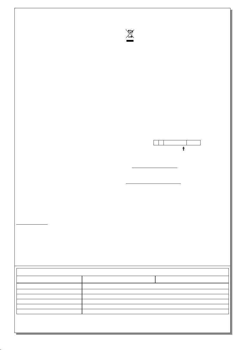
LABELING EXPLANATION:
X: Self contained
4. I s not allowed to discard batteries into t i
common trash bins, they must be
discarded only in battery recycling
points. Do not incinerate.
A: Including test device
NOTE!! The installer should fill in, on the
specification label, the letter G if the luminaire is
used as a safety sign.
180: 3 hours duration
Battery replacement.
Non Maintained operation: The luminaire lights
its illumination source, only in power supply’s
failure.
than 2 months, disconnect the battery by pulling
out the battery’s connector.
NOTE: LED= Light Emitting Diode
1: Maintained (*)
C: Including inhibiting mode
F: Automatic test gear complying with
IEC 61347-2-7 denoted EL-T
B: Including remote test mode
It can be done only by a competent person and
after the mains interruption.
1. Dismantle the device (step 1 of the installation
instructions).
3. Connect the new battery with the same type
(step 4 of the installation instructions) and place
it in the position of the old one.
2. Disconnect the connector and remove the old
battery.
4. Follow the step 6 of the installation procedure
and power the device.
LED MODULE CHARACTERISTICS
Manufacturer
Model Number
Voltage Range
Connections
Nominal Power
Temperature (tc)
Olympia Electronics S.A
45 °C max. across the board
Non reversible connection between main pcb and led module
8.7-10.8VDC
780mW
3105165
GR-2100/ST/M/WL GR-2110/ST/M/WL
X18 0A 1F
G
BC
923211010_09_001


