manuals.online logo
Brands
  1. Home
  2. •
  3. Brands
  4. •
  5. Olympus
  6. •
  7. Laboratory Equipment
  8. •
  9. Olympus OMCL-AC160TS-W2 User manual

Olympus OMCL-AC160TS-W2 User manual

user’s manual 書
Case label
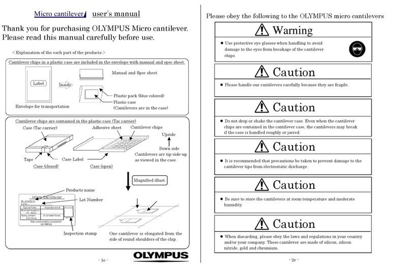
Thank you for purchasing OLYMPUS Micro cantilever.
Please read this manual carefully before use.
Please obey the following to the OLYMPUS micro cantilevers
Warning
Use protective eye glasses when handling to avoid
damage to the eyes from breakage of the cantilever
chips.
- 2e -
Manual and Specification sheet
Case for cantilever wafer
(in a blue plastic pack)
Cantilever chips in a plastic case are included with manual and spec. sheet in the box.
<Explanation of the each part of the products>
user’s manual
Caution
Poly-urethane foam
Please handle our cantilevers carefully because they are fragile.
A cantilever wafer on a base silicon wafer is inside the plastic case. Caution
Do not drop or shake the cantilever case. Even when the cantilever chips
are contained in the cantilever case, the cantilevers may break if the
case is handled roughly or jarred.
Products name
OMCL-AC160TS-W2
300
42
Lot Number
Inspection stamp
Case (closed) Case (open)
Case label
Orientation flat of
the cantilever
wafer
Cantilever
Orientation flat of
the cantilever wafer
Caution
It is recommended that precautions be taken to prevent damage to the
cantilever tips from electrostatic discharge.
Orientation flat of
the base silicon wafer
Frame Cantilever chip
(substrate)
Magnified illust.
Support arm
Cantilever
Caution
Be sure to store the cantilevers at room temperature and moderate
humidity.
Caution
When discarding, please obey the laws and regulations in your country
and/or your company. These cantilevers are made of silicon and
aluminum.
- 1e -
Special feature of OLYMPUS Micro cantilever (OMCL-AC160TS-W2)
- 3e -
1 Preparation
1) Please prepare the followings before using OLYMPUS cantilevers.
1. AC mode cantilever – This type of micro cantilever is for AC (dynamic) mode AFM operation.
2) To gain a better understanding of how cantilevers and chips are connected, cantilevers should
be inspected under the microscope.
High mechanical Q factor of the cantilevers allows you high sensitivity measurement to
probe your sample surface gently. This type of micro cantilever is used as a standard
cantilever for AC mode measurement.
2. Tip View – The tip is located on the very end of the cantilever.
1) Work environment
: Clean bench
(Use of an electrical charge neutralizer of ionizer is recommended.)
This feature allows you to set the tip over a point of interest on the sample, easily and 2) For hazard avoidance
3) For cantilever treatment
: Protective eye glasses
: Tweezers (sharp pointed tip), Tweezers (flat tip)
precisely, if you use an AFM combined with an optical microscope.
- 4e -
4 Tip shape of Tetrahedral tip
3. Point terminated tip – The tip radius is typically 10 nm or less.
A sharpened tetrahedral tip of single crystal silicon is employed for high-resolution
measurements. The tetrahedral shape is ideal for achieving a point terminated tip. In
addition to the geometrical dimensions of the tip, the tip is further sharpened with our
exclusive sharpening process.
4. Symmetric tip – The tetrahedral tip is thin with the macroscopic tip angle of 35 degrees
viewing from both its front and side. Tip shows good symmetry in viewing along the
cantilever axis (see Chapter 4).
Symmetric shape tip results AFM images less distortion which reduce misinterpret of
the data.
5. Reflex coating cantilever – Aluminum is coated onto the back side of the cantilevers for
optical deflection sensing.
Good S/N signal can be expected in the optical sensor circuit.
6. Compatible chip – 3.4 mm(L) x 1.6 mm(W) x 0.3 mm(t)
This type of the chip can be attached to most of AFM instruments.
Table of contents
1 Preparation
2 Open the case
3 Picking up the cantilever chip from the cantilever wafer
5 Trouble-shooting Guide
6 Information
7 Specification 1s
page
4) For inspection
2 Open the case
(Use of those made of insulator is recommended.)
(Use of anti-electrostatic discharge mat and a wrist band is
recommended.)
: Stereo microscope
1) It is recommended that the cantilever case be opened in a clean environment like a clean bench
in order to avoid the cantilever being contaminated. Handling under an ionizer is recommended.
2) Avoid wearing clothes like woolen sweaters, fleece etc that give off the static electricity when
handling the cantilever cases and chips. Use of an anti-electrostatic mat and wrist band is
preferable.
It is recommended that precautions be taken to prevent damage to the
cantilever tips from electrostatic discharge.
Caution
Avoid any contact with the cantilevers when you pull up the
cantilever tip from the case.
Caution
See the specification sheet of OLYMPUS Micro cantilevers at the last page of this manual.
4e
4e
6e
8e
Please handle our cantilevers carefully because they are fragile.
Caution
7. Easy handling – Chip are fixed through the support arms. (Bottom left illust. in the first page)
375 chips are contained in a wafer. A chip can be separated from the wafer frame by
pushing it gently in the middle with a pair of tweezers.
3) In opening the case, put the plastic case label-side down on a desk.
4e
The cantilevers are tip-side-up as viewed in the case.
4) Open the case.
3 Picking up the cantilever chip from the case
8e
1) Keep a working area on the desk. This operation is NEVER carried out in the cantilever case.
2) Place two pieces of paper on the working desk, e.g. Post-itTM which is available in your office.
3) Take out the cantilever wafer from the case with the flat-tip tweezers and place it on the
working desk.
4 Tip shape of Tetrahedral tip
As can be seen in the left illustration, a
tetrahedral tip is located at the exact end of
the cantilever.
Base silicon wafer
The finite tip shape will determine the scan
line profile as in the illustrations below.
Cantilever wafer
The tip profile is symmetric with a half tip
angle of 18 degrees macroscopically (see left
below).
The side tip profile is asymmetric with a tip
angle of 35 degrees. Then the cantilever chip
is attached to a chip holder in your AFM with
an angle, about 10 degrees, the asymmetry is
improved (see right below).
It is recommended that precautions be taken to prevent damage to the
cantilever tips from electrostatic discharge.
Caution
4) As illustrated below, place the papers with a space to hold the cantilever wafer. Make sure
that the space is narrower than the diameter of the cantilever wafer (4 inch or 10 cm).
AA’B B’
less than 4 inch
a piece of
paper
a piece of
paper Replace the cantilever wafer on the two
pieces of paper so that space is left between
the cantilever wafer and the working desk.
A paper-thickness as Post-itTM is good
enough to leave a space between the wafer
and the desk. Do NOT insert thick papers. Tip shape and scan line profile
The apex of the tetrahedral tip becomes sharper due to an oxide sharpening process. The
tip angle around a few hundreds nano meter down from the apex, is about 15 to 25
degrees (see below).
Cantilever
wafer
Space
Working desk
5) Push gently the center of the chip (arrow in
the illustration) with the sharp-pointed
tweezers to snap the support arms
6) Pick up the chip carefully by the long side
with the tweezers and mount it on the
cantilever holder of your AFM.
Press here
7) Put away the cantilever wafer in the case for storage.
- 5e - - 6e -
When you set your samples to your instrument, please consider the unique shape of the
tetrahedral tip, that is ‘good symmetry’, when viewing from its front side and choose the
direction of the sample. When measuring long grooves, you can get an idea of what angle of
the cut will be quickly by aligning the cantilever along the grooves and scanning across at
right angles against grooves (see below).
Case: In adjusting the sensor optics before scanning, the movement of the reflection spot on
the photo detector is critical so that the sensor optics is hard to adjust to zero position.
When the sensor illumination spot on the cantilever is not small enough and is positioned
at the triangular part of the cantilever, unexpected reflection and light scattering occur.
This may cause the unexpected movement of the reflection spot on the photo detector.
Ver. 4.0 Sep. 18, 2009
OLYMPUS CORPORATION
2-3 Kuboyama-cho Hachioji-shi Tokyo 192-8512 Japan
email : [email protected]
Microtechnology R&D Division
Please contact following if you have any question on this user’s manual.
OLYMPUS CORPORATION
Please access to the web page of OLYMPUS micro cantilevers.
http://www.olympus.co.jp/probe
Solution:
Try to adjust the focus of the sensor optics again and move the spot position a little
opposite to the free end of the cantilever.
Situations as described below may arise when using this type of cantilever.
5 Trouble-shooting Guide
6 Information
- 8e -- 7e -

Other Olympus Laboratory Equipment manuals

Olympus SZX2-ILLT User manual

Olympus

Olympus SZX2-ILLT User manual

Olympus SZX-SDO2 User manual

Olympus

Olympus SZX-SDO2 User manual

Olympus OER-Elite User manual

Olympus

Olympus OER-Elite User manual

Olympus SZX2-EEPA User manual

Olympus

Olympus SZX2-EEPA User manual

Olympus U-APT User manual

Olympus

Olympus U-APT User manual

Olympus UHI-4 User manual

Olympus

Olympus UHI-4 User manual

Olympus MX61A User manual

Olympus

Olympus MX61A User manual

Olympus ENDO-AID User manual

Olympus

Olympus ENDO-AID User manual

Olympus CX-DO User manual

Olympus

Olympus CX-DO User manual

Olympus CIX100 User manual

Olympus

Olympus CIX100 User manual

Olympus U-LH50HG User manual

Olympus

Olympus U-LH50HG User manual

Olympus U-UCD8A User manual

Olympus

Olympus U-UCD8A User manual

Olympus CKX-CCSW User manual

Olympus

Olympus CKX-CCSW User manual

Olympus SZ2-STU1 User manual

Olympus

Olympus SZ2-STU1 User manual

Olympus HysteroFlow User manual

Olympus

Olympus HysteroFlow User manual

Olympus SZX2 Series User manual

Olympus

Olympus SZX2 Series User manual

Olympus SZ2-STS User manual

Olympus

Olympus SZ2-STS User manual

Olympus AL120-6Series User manual

Olympus

Olympus AL120-6Series User manual

Olympus U-SRG User manual

Olympus

Olympus U-SRG User manual

Olympus DP2-SAL User manual

Olympus

Olympus DP2-SAL User manual

Olympus 72DL PLUS User manual

Olympus

Olympus 72DL PLUS User manual

Olympus SZX-DO User manual

Olympus

Olympus SZX-DO User manual

Olympus BioLever mini User manual

Olympus

Olympus BioLever mini User manual

Olympus OMCL-TR800PSA User manual

Olympus

Olympus OMCL-TR800PSA User manual

Popular Laboratory Equipment manuals by other brands

VWR Standard Series instruction manual

VWR

VWR Standard Series instruction manual

Hach BODTrak II Basic user manual

Hach

Hach BODTrak II Basic user manual

Thermo Scientific Neslab EX-7 Installation, Operation, Basic Maintenance

Thermo Scientific

Thermo Scientific Neslab EX-7 Installation, Operation, Basic Maintenance

YMC Pilot PLUS manual

YMC

YMC Pilot PLUS manual

Technik TUV-45SSN quick start guide

Technik

Technik TUV-45SSN quick start guide

PerkinElmer Panthera-Puncher 9 user manual

PerkinElmer

PerkinElmer Panthera-Puncher 9 user manual

Analytik Jena qTOWER3 operating manual

Analytik Jena

Analytik Jena qTOWER3 operating manual

Dado Lab QB1 user manual

Dado Lab

Dado Lab QB1 user manual

corob EVOSHAKE 500 V2 user manual

corob

corob EVOSHAKE 500 V2 user manual

IKA RET control operating instructions

IKA

IKA RET control operating instructions

Beckman Coulter StatSpin Express 4 M510 Instructions for use

Beckman Coulter

Beckman Coulter StatSpin Express 4 M510 Instructions for use

Biotage V-10 Touch user manual

Biotage

Biotage V-10 Touch user manual

Eisco PH0619 instruction manual

Eisco

Eisco PH0619 instruction manual

Thermo Electron C3i user manual

Thermo Electron

Thermo Electron C3i user manual

ARA Smart 6 manual

ARA

ARA Smart 6 manual

Thermo Scientific Heratherm OGS Series operating instructions

Thermo Scientific

Thermo Scientific Heratherm OGS Series operating instructions

Atlas XENOTEST ALPHA operating manual

Atlas

Atlas XENOTEST ALPHA operating manual

NVIS 18 instruction manual

NVIS

NVIS 18 instruction manual

manuals.online logo
manuals.online logoBrands
  • About & Mission
  • Contact us
  • Privacy Policy
  • Terms and Conditions

Copyright 2025 Manuals.Online. All Rights Reserved.