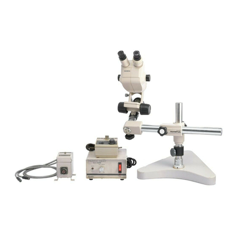
Olympus X-Tr Operating instructions

OLYMPUS
TRINOCULAR
STEREO
MICROSCOPE
~LX-Tr
REPAIR
MANUAL
o·LYMPU.S

P R E F A C E
The
functions
of
a
microscope
can
be
analyzed
into
the
mechanical
and
optical
systems.
To
those
who
are
engaged
in
line
of
microscope
repair,
it
is
a
self-
evident
truth
that
if
the
optical
system
is
not
correctly
adjusted,
the
fundamental
function
of
the
microscope
may
be
lost.
Among
the
various
types
of
microscopes,
the
stereo
microscopes
such
as
the
OLYMPUS
Stereo
Microscopes
Models X and X-Tr
require
most
difficult
and
complicated
tech-
niques
to
repair.
Prior
to
repair
of
them,
read
this
manual
and
make
yourself
familiar
with
these
models
so
that
you
can
find
what
parts
are
defective
and
degrees
of
their
damages.
In
case
of
the
Models X
and
X-Tr
it
is
necessary,
first
of
all,
to
find
out
what
lens(es)
or/and
prism(s)
is(are)
the
cause(s)
of
the
microscope
mulfunction.
Checks
and
repairs
of
these
models
should
be
carried
out
in
the
following
orders:
1.
Porro
prisms
2,
Parfocality
of
drum
lenses
3.
Total
deviation
of
drum
lenses
4.
Optical
axes
of
left
and
right
fields
of
view
Each
of
these
4
items
can
be
checked
and
repaired
individually.
However,
if
you
observe
a
double
image
through
the
binocular
observation
tube,
for
instance,
the
optical
axes
of
the
left
and
right
fields
of
view
are
not
coincided,
simultaneous-
ly
and
totally
due
to
the
items
1,
3,
and
4
mentioned
above,
These
3
steps
must
be
repaired
in
the
order
1-3-4,
You
cannot
change
this
order,
because
if
you
complete
steps
3
and
4
prior
to
step
1,
you must
repeat
checks
and
repairs
steps
3
and
4
after
completing
step
1.
If
you
get
skilled
in
repair
of
the
Model X
and
X-Tr,
the
optical
adjustments
of
the
other
OLYMPUS
Stereo
Microscopes
except
the
Model
SZ-III
become more
easier
because
they
are
of
the
same
optical
system.
(Your comments
are
welcome on
this
manual
for
improvements
of
other
manuals.)

C 0 N T E N T S
A.
SEQUENTIAL
PROCEDURE
OF
DISASSEMBLY
••••••••••••••••••••••••••••••••••••••••
2
1.
Disassembly
of
Focusing
Mechanism • • • •• •. • • . • • •• • • .
•••.•••.•••.•••
2
2.
Disassembly
of
Main Body and Lens
Drum
•••••••••••
•••••••••••••.•••.••
2
3.
Disassembly
of
Objective
Mount •• •• •• . • . •• •
•.••.•.•.•••.•.•••.••••.•••••
4
4.
Disassembly
of
Prism
Mount
.••..............................•...••...•.....
4
5.
Disassembly
of
Trinocular
Tube
••••••••••••••••••·•••••••••••••••••••••••••
6
B.
SEQUENTIAL
PROCEDURE
OF
OPTICAL
ADJUSTMENTS
..••••••••••••••••••••••••••••.••
8
1.
Tools
and
Test
Plate
•...•...................•..••..•....•..•••..••..•
• • • • • 8
2.
Porro-prism
Cent
ration
.•.•••••..............•....•..•..•.•....••.•.•.
• • • • • 8
3.
Adjustment
of
Click
Spring
•••.•.••••••••••.••.••••••••••••••.••••••
• • •• • •
•10
4.
Focusing
of
Drum
Lenses
in
the
Right
Field
of
View
••••••••·•••••••••••••••11
5.
Centration
of
Drum
Lenses
in
the
Right
Field
of
View
•••••••••••·•••·••••••12
6.
Adjustment
of
Left"
Diopter
••••••••••••••••••••.•••••.•••••••••..••••
• ·
••
••15
7.
Centration
and
Focusing
of
Drum
Lenses
in
the
Left
Field
of
View
••••••••••16
8.
Attachment
of
Dust
Glass
•••••••••••••••••••·•••••••••••••••·••••••••••••••17
9.
Coincidence
of
Right
and
Left
Optical
Axes
•••···•·················••••·•••17
10.
Mounting
of
PM-6
••.•••...•.•••...••••..•.•..•.••••••..•••..••.•
• •
•••
• • • • •
•18
11.
Focusing
of
Phototube
Objectives
••·········••••••••••••••••••••·••••••••••18
12.
Centration
of
Drum
Lenses
for
Phototube
•••••••••••••••••••••••••••••••••••19
13.
Coincidence
of
Optical
Axes
through
Phototube
and
Binocular
Tube
•••••·····19
14.
Mounting
of
Dust
Glass
and Covers
••••••••••··············•••••••••••••••••20
C.
PRACTICAL
POINTS
OF
REPAIRS
•.••••••••••••••••••••••••••••••••••••••••••••••
21
1.
Sticking
on
Abrasive
Surfaces
of
Focusing
Mechanism
••.•••••••.••••••••••••
21
2.
Chatter
on
Abrasive
Surfaces
of
Focusing
Mechanism
••••••••••••••.•••••••••
22
3.
Defective
Rack
and
Pinion
of
Focusing
Mechanism
•••••••••••••••••••••••••••23
4.
Heavy
Rotation
of
Focusing
Knob
...•••.••••••••..•••••••.••••••••••••
26
5.
Heavy
Rotation
of
Helicoid
Rings
•••
·•••···········••••••••••••••••••••••26
6.
Defective
Binocular
Vision
••••••••.••••...••••••••.•••••••••••••••••••••••
28
- 1 -
Fig.
1
0 AA 0738
1-.3)
Z-S)
AA 6207
z-S)
AA 4866

A.
SEQUENTIAL
PROCEDURE
OF
DISASSEMBLY
(See
Fig.
1)
1.
Disassembly
of
Focusing
Mechanism
1-1)
Rotate
focusing
knobs
until
main body
goes
up
as
well
as
possible.
1-2)
Unscrew
~038
that
can
be
seen
in
dovetail
block
AA4869.
1-3)
Disengage
metal
block
AA0738
from
dovetail
AA4869.
Rotate
focusing
knobs,
and
lower
main
body so
that
rack
and
pinion
are
disengaged,
and
pull
out
metal
block.
1-4)
Remove
focusing
knobs AA0005.
Holding
both
of
focusing
knobs
in
both
hands,
rotate
them
in
the
oppo-
site
directions
simultaneously
so
that
they
are
loosened.
When
they
are
completely
loosened,
focusing
knob
AA0005
and
nut
AA0008
are
disengaged.
1-5)
Pull
out
pinion
from
bearing.
As
you
pull
out
focusing
knob
AA0006
in
the
axial
direction,
pinion
can
be
pulled
out.
1-6)
Unscrew two
CMK4x20SA
and
pull
out
block
AA4869
from
main
body.
2.
Disassembly.
of
Main Body and Lens
Drum
2-1)
Unscrew
four
CMK3xl0SA
and
pull
out
fixing
guide
AA4947.
2-2)
Unscrew two
SK1.4-21,
and remove
cover
plate
AA4948.
2-3)
Remove
three
glass
discs
LP0387.
Prior
to
removal,
immerse
three
glass
discs
with
a
little
amount
of
alcohol
for
a few
minutes,
because
these
discs
were
shellaced,
then
stick
them
to
Scotch
tape
to
remove
with
ease.
2-4)
Unscrew two
HK2x4SA,
and
remove
click-spring
AA4858.
2-5)
Unscrew
left
knob AA4861.
After
removal
of
screw
AA4866,
insert
a
small
screwdriver
through
empty
hole
to
loosen
setscrew
AA6207.
Knob
can
be
removed.
- 3 -

2-6)
AA
4863
{
HK2X4SA_/
3-1)
/
AA
4956
Fig.
2

(See
Fig.
2)
2-6)
Unscrew
four
HK2.6x5SA and remove
bearing
AA4863.
2-7)
Disassemble
right
knob
AA4860
from
bearing
AA4862
in
the
same manner
as
above.
2-8)
Pull
out
lens
drum.
3.
Disassembly
of
Objective
Mount
3-1)
Unscrew
four
HK2x4SA
and remove
objective
cover
AA4956.
3-2)
Unscrew
four
HK2.6xl5SA and remove
adjusting
washer
AA4954.
3-3)
Unscrew
objectives.
Unscrewing NU2.6x5SA and NU2.6x8SA, remove
retaining
frame AA4876.
When
this
frame was
shellaced,
immerse
it
with
alcohol
for
a few
minutes
prior
to
removal,
then
loosen
it.
Objective
frame
AA4955
can
be
removed
'r..-J
'"lt:!ruuv'.mg
"t:wo
screws
""Hl("Lx4BB.
4.
Disassembly
of
Prism
Mount
4-1)
Unscrew
four
HK2.6xl2SA, and remove
prism
mount
AA4949
and
plate
AA4953.
4-2)
Unscrew
four
3PUK1.
7x3SA
and remove two
P-holders
AA4871.
4-3)
Unscrew two HK1.4x2.5Sli, and remove
P-holder
AA4952.
4-4)
Loosen
three
HU2x4SA,
and
then
remove two
prisms
LP0386,
prism
LP0392
and
three
side
plates
AA3399.
- 5 -

•
S-ltJ)
•
AA
4968
S-!O)AA
4886
5-9)
AA
4962
AA 6203
5-13)
{ 0 AA 0722
5-/)
AA
4906
Cli)...
8 AA 4892
5-15)
HK
1.7
X
4Sj
5
_.3)
SK1.7X4SA
AA
12871~
AA 4078 )

(See
Fig.
3)
5.
Disassembly
of
Trinocular
Tube
5-l)
Unscrew
left
eyepiece
tube.
Insert
flat-tip
divider
into
eyepiece
tube,
and
rotate
nut
AA4906
counter-clockwise.
5-2)
Unscrew
three
PQK1.7x3.5SA, and
cover-L
AA4903.
5-3)
Unscrew
three
SK1.7x4SA, and OC-mount-L
AA4901.
5-4)
Disassemble
porro-prism.
Unscrew
three
NU2.6x6SA
and
take
out
prism
mount-L
AA4895.
Unscrew
four
PUK2x4SA,
porro-prism,
pressing
plate
AA4077,
plate
AA1287
and
plate
AA4078.
5-5)
Disassemble
right
porro-prism
in
the
same manner
as
above
with
the
exception
that
eyepiece
tube
is
unscrewed by
rotating
it
counter-clock-
wise.
5-6)
By
rotating
counter-clockwise,
remove
upper
part
of
phototube
including
inner
sleeve
AA4964
and above.
5-7)
Unscrew
two
PQK1.7x3.5SA, and remove
cover
AA4963.
5-8)
Unscrew
two
HK2-242SA, and remove
F-frante
AA4966.
5-9)
Unscrew
four
HK2-242SA
and remove
dovetail
AA4962.
5-10)
Unscrew
four
HK2-342SA
and remove
washer
AA4886.
5-11)
Unscrew
four
HK3x4.
5
SA
and remove
holding
block
AA4960.
5-12)
Unscrew
nut
AA4145
by
rotating
it
counter-clockwise
with
round-tip
divider.
5-13)
Unscrew two
HK
AA6203
on
right
and
left
sides
respectively.
5-14)
Remove
belt
AA4896.
5-15)
Remove
prism
housings
AA4891
and
AA4892,
by
pulling
them from
holding
block
AA4960.
5-16)
Unscrew
four
HK2x3BB,
and remove
two
prism
holders
AA4899.
5-17)
Unscrew
four
HU2x3SA,
and remove
two
prisms
LP0388 and two
side
frames
AA0255.
5-18)
Disassemble
phototube.
a.
Rotate
cover
AA4970.
b.
Loosening
three
NU2.6x3.5SA, remove
inner
sleeve
AA4964.
c.
Unscrew
3PUK2x4SA,
and remove
eyepiece
tube
AA4968.
- 7 -

B.
SEQUENTIAL
PROCEDURE
OF
OPTICAL
ADJUSTMENTS
1.
Tools
and
Test
Plate
a.
Eyepiece
with
cross
hairs
GlOX
b.
Focusing
telescope
c.
Screwdrivers
d.
Dividers,
flat
and
ball
tips
e.
Photomicrographic
equipment Model
PM-6
f.
Shellac
(adhesive)
g.
Test
plate
with
5/100
concentric
circles
2.
Porro-Prism
Centration
*
Porro-prisms
should
be
centered
within
a
range
of
interpupillary
distance.
Working
Steps
2-1)
Remove
right
and
left
eyepiece
tubes.
2-2)
Remove
covers
AA4902
and AA4903.
2-3)
Mount
right
and
left
eyepiece
tubes.
2-4)
Mount main body on
stand
and
place
test
plate
(5/100
concentric
circles)
on
stage.
Set
test
plate
in
position
with
stage
clips.
2-5)
Insert
eyepiece
with
cross
hairs
GlOX
into
right
eyepiece
tube.
2-6)
Set
drum
lens
40X
into
position,
and
bring
concentric
circles
into
focus.
Coincide
cent~rs
of
concentric
circles
and
cross
hairs
of
eyepiece.
- 8 -
Remarks
2-4)
I •
Test
Plate
(5/100
concentric
circles)
2-6)
Concentric
circles
Cross
hairs
Centered
•
x~5tZ

2-7)
Maximize
or
minimize
interpupillary
2-7)
distance,
and
if
these
centers
are
not
concentric,
optical
axes
are
eccentric.
2-8)
Adjustment
of
optical
axes
Adjust
optical
axes
so
that
centers
of
concentric
circles
and
cross
hairs
do
not
depart
from
each
other
even
at
maximum
or
minimum
interpupillary
distance.
a.
After
coinciding
centers
of
cross
hairs
and
concentric
circles,
rotate
prism
housings.
b.
If
center
of
concentric
circles
moves,
detennine
center
of
the
move-
ment from
the
locus
of
its
movement
(concentric
circles
move
centering
around
this
center).
c.
Coincide
locus
center
and
center
of
concentric
circles.
(Move
test
plate)
d.
After
determination
of
locus
center,
rotate
three
screws
NU2.6x6SA
to
move
prism
and
prism
mount
AA4894
together
until
centers
of
cross
hairs
and
concentric
circles
are
coincided.
e.
Repeat
steps
above
until
cent
ration
is
complete.
11len clamp
screws.
Allowance
of
centeringdeviation:
0.2
on image
plane
f.
Follow
steps
above
with
left
porro-prism.
- 9 -
Before
rotation
2-8)
b.
2-8)
Co
Prior
to
centiation
2-8)
d.
o.os-j
r
ro.2S
Decent
ration
after
rotation
~f
locus
\
After
coincidence
2-8)
e
0.2
(on
image
plane)
=
Obj.
magnification
(on
zoom
scale)
x
Distance
(on specimen
surface)
Ex.
Zoom
scale
• 4
0.2
• 4 X X
0.2
X • 4 =
0.05
The
allowance
0.05
at
zoom
scale
4
equals
one
graduation
of
the
concentric
circle
from
the
center.

2-9)
Remove
right
and
left
eyepiece
tubes.
2-10)
Place
right
and
left
covers
AA4902
&
AA4903
.•
2-11)
Mount
right
and
left
eyepiece
tubes.
2-12)
Again
confirm
centration
of
optical
axes.
3.
Adjustment
of
Click
Spring
3-1)
Set
drum
lens
16X
into
position,
insert
eyepiece
with
cross
hairs
GlOX
into
right
eyepiece
tube,
and
coincide
centers
of
concentric
circles
and
cross
hairs.
3-2)
By
changing
drum
lens
magnification
to
40X
and
then
to
6.3X,
check
movement
of
image
in
north-south
direction.
a.
In
case
that
image moves upward
(north
direction)
at
40X, and
downward
(south
direction)
at
6.3X
in
conjuction
with
16X
drum
lens,
loosen
screw
that
affixes
click
spring,
and
move
click
spring
closer
to
you
slightly,
until
images
at
40X
and
6.3X
are
almost
equidis-
tant
from
center
(16X).
b.
In
case
that
40X
image
is
downward,
and 6.3X upward,
reverse
click
spring
until
these
images
are
almost
equidistant
from
center
(16X).
-10 -
2-8)
e.
Take
care
that
when
eyepiece
tubes
are
mounted,
left
eyepiece
tube
is
apt
to
deviate
from
center,
which
requires
re-centration.
2-12)
Even though
prism
housing
is
rotated,
center
of
cross
hairs
should
not
depart
from
center
of
concentric
circles.
3-2)
a.
X Image
center
(40X)
X (16X)
x (6.3X)
Click
moves
0
·0
closer
to
you.
Lox
xl6X
x6.3X
t
Image
centers
get
closer
to
that
of
16X.

3-3)
Ascertain
that
25X
and
lOX
images
are
coincided
to
16X
i~ge
by
steps
above.
4.
Focusing
of
Drum
Lenses
in
the
Right
Field
of
View
4-1)
Rotate
drum
to
position
16X,
insert
eye-
4-1)
piece
GlOX
into
right
eyepiece
tube,
and Use
eyepiece
GlOX
(f=25~and
focus
with
focusing
telescope.
4-2)
Check
deviation
direction
of
focus
at
40X
and 6.3X
in
comparison
with
16X.
a.
In
case
focus
is
"below"
at
6.3X
in
comparison
with
16X,
move
prism
P2
forward
until
focuses
of
40X
and
6.3X
are
in
the
same
direction
and
equidistant.
b.
In
case
focus
is
"below''
with
drum
lens
6.3X,
move
prism
P2
forward
until
focuses
of
40X
and 6.3X
are
in
the
same
direction
and
equidistant.
4-3)
Coincide
focus
of
40X
and 6.3X
to
that
of
16X.
a.
If
focus
of
6.3X
is
above
that
of
focusing
telescope
should
be
matched
for
focusing
with
this
eyepiece.
If
microscope
main body
has
to
be
moved
upward
with
focusing
knobs
to
obtain
correct
focus,
this
state
is
called
"focus
is
above":
on
the
contrary,
if
main body
has
to
be
lowered,
it
is
called
"focus
is
below''.
4-2)
a.
16X,
lift
40X
drum
lens
(LA4174), by
4-2)
b.
rotating
two
setscrews
counterclock-
wise
equally.
b.
If
focus
of
40X
is
below
that
of
16X,
lower
40X
drum
lens
by
rotating
two
setscrews
clockwise
equally.
4-4)
Coincide
focus
of
25X
and
lOX
to
that
of
16X.
-
ll
-
P2
moves
in
this
direction.

a.
If
focus
of
25X
is
above
that
of
16X,
lift
25X
drum
lens
(LA4212)
by
rotating
two
setscrews
counter-
clockwise
equally.
b.
If
focus
of
25X
is
below
that
of
16X
,
lower
25X
drum
lens
by
rotat-
ing
two
setscrews
clockwise
equally.
4-3)
Drum
lens
40X
can
be
moved up and
down
by
aid
of
spring
located
beneath
drum
lens,
for
focus
adjustment.
4-3)
a.
0 -.J Focus
~
-~-
40X, 6.3X
Drum
lens
40X
--
16X
4-3)
b.
G 0
~
Focus
r.:
t
_..:...,__ 40X, 6.3X
4-4)
Drum
lens
25X
can
be
moved up and
down
by
aid
of
spring
beneath
drum
lens
for
focus
adjustment.
4-4)
a.
O
~
Drum
lens
25X
4-4)
b.
6 0
~
Focus
~
-~-25X,
--16X
lOX
Focus
I
16X
--
25X,
lOX
5.
Centration
of
Drum
Lenses
in
the
Right
Field
of
View
5-l)
Set
drum
lens
16X
into
position,
insert
eyepiece
with
cross
hairs
GlOX
into
right
eyepiece
tube,
and
coincide
the
-12 -

centers
of
concentric
circles
and
cross
hairs.
5-2)
Coincide
image
of
40X
and 6.3X
to
that
of
16X.
a.
If
image moves
over
a
long
distance
at
different
magnifications
(dis-
tance
more
than
0.8mm
in
image
plane),
swing
prism
P2
to
the
right
or
left,
until
images
of
40X
and
6.3X
are
coincided
on
vertical
center
line
of
16X.
a-1.
In
case
image
of
40X
moves
to
the
right,
and image
of
6.3X
to
the
left.
a-2.
In
case
image
of
40X
moves
to
the
left,
and image
of
6.3X
to
the
right.
b.
Adjustment
of
vertical
and
horizon-
tal
image
positions
at
40X
and 6.3X.
Coincide
optical
axes
of
40X
and
6.3X
to
that
of
16X
by movement
of
40X
drum
lens
and B
lens.
* Image movement by
adjustment
of
drum
lens:
b-1.
Image movement by
adjustment
of
drum
lens
40X.
Move
lens
frame
of
40X
drum
lens
by
prying
it
with
screwdriver
tip
in
a
range
as
screw
clearance
allows.
b-2.
North-south
movement
of
optical
axis.
b-3.
East-west
movement
of
optical
axis.
-13 -
5-2)
a.
"
"
'
"
~
P2
(
~
'
'
a-1.
16X
6.3X
X
a-2.
16X
m
!il
40X
X
---
Put
tin
foils
at
the
side
of
prism
P2
and
rotate
two
screws
alternately
to
swing
prism
to
the
right
or
left
as
desired.
B-=
Swing
prism
P2
in
arrows'
directions.
40X
6.3X
Swing
prism
P2
in
arrows'
directions.
X X
5-2)
b.
B
lens
AA4889
is
positioned
beneath
inclined
prism.
b-1.
--

b-4.
Image movement by
adjustment
of
B
lens
AA4889.
B
lens
can
be
moved
by
rotation
of
three
setscrews.
b-5.
North-south
movement
of
optical
axis.
b-6.
East-west
movement
of
optical
axis.
-14 -
b-2.
+
X
40~
@
J6x.
><
/..3'1l
)l~.3X
(§]
---;/;>(
0
X.
4PX §
b-3.
~.
3
)(
16
!<
40x
')(
X
b-5.
"\
If.
4D
>(
---liJ(
x t.3x
b-6.
\ .
I )(
\.\
i
=:::::;:>
~
,c:
40x
i
t
/bx
'(
6.3'(
)(
6.3
~
J6
:<.
t
x
40><
6.3"<
)(
)(
I J
.,
tt
4~1-.
t.3X
>(
4lJx
/6'/l
6.3l(

·•
c.
Examples:
c-1.
40X
image moves
to
the
left,
and
6.3X image
to
the
right.
c-2.
Lower
40X
drum
lens
until
40X
image
is
aligned
with
horizontal
center
line
of
16X.
c-3.
Move
40X
drum
lens
to
the
right
until
40X
image
is
at
equidistant
from
north-south
optical
axis
of
16X.
c-4.
Move
B
lens
to
the
right
until
image
of
40X
and 6.3X
are
coincided
with
image
of
16X.
5-3)
Adjustment
of
image movement
of
25X
and
lOX
in
north-south
and
east-west
direc-
tions.
Coincide
optical
axes
of
25X
and
lOX
to
that
of
16X
by movement
of
25X
drum
lens.
5-4)
Steps
5-2)
and
-3)
sometimes
require
repetition
until
adjustment
is
complete.
Ascertain
coincidence
of
optical
axes
of
40X, 25X, 16X,
lOX
and 6.3X.
6.
Adjustment
of
Left
Diopter
6-1)
Insert
eyepiece
GlOX
into
right
eye-
piece
tube,
bring
drum
lens
16X
into
path,
and
focus
on specimen by
use
of
focusing
telescope.
6-2)
Coincide
focus
of
left
drum
lens
16X
to
that
of
right
16X.
a.
When
focus
is
deviated
to
the
"+"
side
(or
eyepiece
tube
is
length-
ened),
move
prism
P2
backward
until
focus
is
obtained
by
aligning
helicoid
ring
to
position
"O".
-
15
-
c-1.
c-2.
•
4-0X
c-3.
t:f'
c-4.
5-3)
There
is
correspondence
between
the
image movements
of
25X
and 40X;
lOX
and
6.3X,
respectively.
This
adjustment
does
not
require
movement
of
B
lens.
6-1)
Make
it
sure
that
when
helicoid
ring
on
left
eyepiece
tube
is
positioned
to
"O",
left
drum
lens
16X
must
be
brought
into
focus.
a.
b.

b.
If
focus
is
deviated
to
the
"-"
side
(or
eyepiece
tube
is
shortened),
mov
prism
P2
forward
until
focus
is
obtained
by
aligning
helicoid
ring
t
position
"0".
7.
Centration
and
Focusing
of
Drum
Lenses
in
the
Left
Field
of
View.
7-1)
Bring
drum
lens
16X
into
light
path,
insert
eyepiece
GlOX
into
left
eyepiece
tube,
and
focus
on
specimen
with
focusing
telescope.
7-2)
Coincide
focus
of
drum
lenses
40X
and
6.3X
to
that
of
drum
lens
16X.
7-3)
Coincide
focus
of
drum
lens
25X
and
lOX
to
that
of
drum
lens
16X.
7-4)
Bring
drum
lens
16X
to
light
path,
insert
eyepiece
with
cross
hairs
GlOX
into
left
eyepiece
tube
and
coincide
centers
of
concentric
circles
and
cross.
hairs.
7-5)
Coincide
image
of
specimen
at
40X
and
6.3X
to
image
at
16X
7-6)
Coincide
images
at
25X
and
lOX
to
that
at
16X.
7-7)
Repeat
steps
7-3),
7-5)
and
7-6)
until
adjustment
is
complete.
-
16
-
7-2)
Move
drum
len's
40X
up and
down
by
aid
of
spring
located
beneath
drum
lens,
until
focus
is
adjusted,
in
a same manner
as
in
4-3).
7-3)
Move
drum
lens
25X
up and
down
by
aid
of
spring
located
beneath
drum
lens,
until
focus
is
adjusted
in
a same manner
as
in
4-4).
7
-5)
Follow
step
5-2).
7-6)
Follow
step
5-3).

8.
Attachment
of
Dust
Glasses
8-1)
Place
dust
glasses
in
position
on
both
sides,
and
shellac
them
at
three
spots
respectively.
8-2)
Sometimes image moves
at
magnification
8-2)
change
after
dust
glasses
are
attached.
See
5-2).
This
can
be
corrected
by
adjustment
of
B
lens.
9.
Coincidence
of
Reight
and
Left
Optical
Axes
9-1)
Check
difference
between
right
and
left
9-1)
optical
axes
in
both
fields
of
view
in
conjunction
with
drum
lens
40X
and
eye-
piece
with
cross
hairs
GlOX
in
position.
9-2)
Eliminate
this
difference
by
equally
moving
right
and
left
objectives.
*
Difference
allowance:
0.2
on
image
plane
-17 -
Ex.
Left
field
Left
field
Left
obj.
Right
field
Right
field
Right
obj.

10.
Mounting
of
PM-6
10-1)
Lift
sliding
sleeve
as
well
as
possibl
along
phototube,
and
clamp.
10-2)
Insert
eyepiece
PlOX
into
PM-6,
and
attach
it
on
sliding
sleeve.
10-3)
Apply
focusing
telescope
to
viewer
of
PM-6
and
looking
through
viewer,
bring
image
into
focus
on
focusing
screen.
11.
Focusing
of
Phototube
Objectives
11-1)
Bring
drum
lens
16X
into
light
path,
· and
looking
through
binocular
obser-
vation
tube,
focus
on
specimen.
11-2)
Looking
through
viewer
of
PM-6,
lower
sliding
sleeve
along
phototube
until
concentric
circles
are
focused.
11-3)
Check
distance
from
focus
of
40X
and
6.3X
to
that
of
16X, and
adjust
photo-
tube
objective
into
position
for
correct
focusing.
11-4)
Move
drum
lens
40X
up
and
down
until
focus
of
40X
and
6.3X
is
coincided
with
that
of
16X.
11-5)
Move
drum
lens
25X
up and
down
until
focus
of
25X
and
lOX
is
coincided
with
that
of
16X.
11-6)
Repeat
steps
11-3),
4)
and
5)
until
adjustment
is
complete.
-18 -
11-3)
Move
phototube
objective
up
and
down
so
that
focus
of
40X
and
6.3X
is
in
the
same
direction
and
equidistant.
In
case
focus
of
40X
is
in
the
opposite
direction
to
that
of
6.3X,
lift
phototube
objective.
11-4)
See
steps
4-1)
through
4-4).
Other manuals for X-Tr
1
Table of contents
Other Olympus Microscope manuals

Olympus
Olympus CX41 User manual

Olympus
Olympus DP26 User manual

Olympus
Olympus BX2 SERIES User manual

Olympus
Olympus V60 User manual

Olympus
Olympus DP22 User manual

Olympus
Olympus SZ3060 Operating instructions

Olympus
Olympus BHT User manual

Olympus
Olympus BXFMA User manual

Olympus
Olympus Lext OLS3100 User manual

Olympus
Olympus FHT-521 User manual

Olympus
Olympus DP74 User manual

Olympus
Olympus BXFM User manual

Olympus
Olympus SZX16 User manual

Olympus
Olympus CX40 User manual

Olympus
Olympus FH User manual

Olympus
Olympus AH3 Operating instructions

Olympus
Olympus FV3000 User manual

Olympus
Olympus BHA-P User manual

Olympus
Olympus MIC-D User manual

Olympus
Olympus STM7 User manual