manuals.online logo
Brands
  1. Home
  2. •
  3. Brands
  4. •
  5. Omron
  6. •
  7. Accessories
  8. •
  9. Omron E3S-LS3 User guide

Omron E3S-LS3 User guide

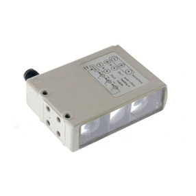
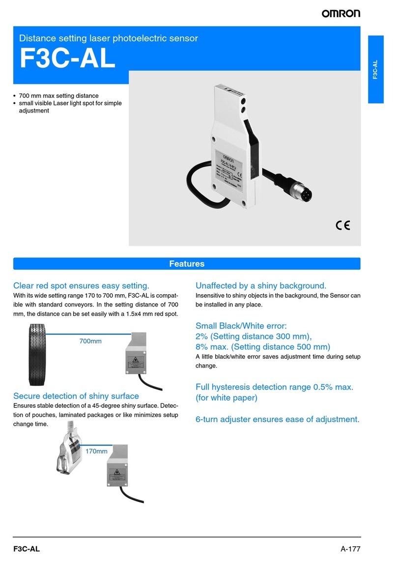
E3S-LS3
A-145E3S-LS3
Printed Circuit Board Sensor
E3S-LS3
Printed circuit board
sensor capable of sta-
ble detection without
being affected by
holes or notches.
• Suitable for incorporation in devices
(E3S-LS3@).
• Wide range is suitable for component
boards with high or irregularly shaped
components (E3S-LS3@W).
Applications
Detecting for PCBs Transparent Film Sheet
Detection
Detection for Wafer-
cassette Mounting
F502-EN2-04.book Seite 145 Dienstag, 26. Juli 2005 5:48 17
A-146 Standard Photoelectric Sensors
Ordering Information
* Using 80 x 80 mm white art paper
Rating/performance
Sensor type Shape Connection method Detection distance * Timer
function Model Output
Limited reflective
Pre-wired (2 m) Without
E3S-LS3N NPN
Light ON
E3S-LS3NW
Pre-wired (2 m) Without E3S-LS3P
PNP
Light ON
With E3S-LS3PT
Pre-wired M8
3-pin connector (0.3 m)
Without E3S-LS3P-M5J
With E3S-LS3PT-M5J
Pre-wired M8
4-pin connector (0.3 m)
Without E3S-LS3P-M3J
With E3S-LS3PT-M3J
Pre-wired (2 m) Without E3S-LS3PW
With E3S-LS3PWT
Pre-wired M8
3-pin connector (0.3 m)
Without E3S-LS3PW-M5J
With E3S-LS3PWT-M5J
Pre-wired M8
4-pin connector (0.3 m)
Without E3S-LS3PW-M3J
With E3S-LS3PWT-M3J
Sensor type Limited reflective
Item Model E3S-LS3@E3S-LS3PT E3S-LS3@WE3S-LS3PWT
Sensing
White art paper
20 to 35 mm 10 to 60 mm
Black paper *
20 to 30 mm 15 to 50 mm
Light source (wave length) Red LED (660 nm)
Power supply voltage 12 to 24 VDC±10%, ripple (p-p) 10% max.
Current consumption 25 mA max.
Control output Load power supply voltage: 24 VDC max.; Load current: 100 mA max.,
Residual voltage: 2 V max.; Operating mode: Light ON
Response time 1 ms max. for operation and reset respectively
Timer function Available with E3S-LS3P(W)T models only. Time range: 0.1 to 1.0 s (adjustable)
Ambient illuminance Receiver side: Incandescent lamp: 5,000 lux max.
Ambient temperature Operating: −10 to 55°C (with no icing or condensation)
Ambient humidity Operating:35% to 85% (with no condensation)
Insulation resistance 20 MΩmin. (at 500 VDC) between charged parts and the case
Dielectric strength 1,000 VAC at 50/60 Hz for 1 minute between charged parts and the case
Vibration resistance 10 to 55 Hz with a 1.5-mm double amplitude for 2 hrs each in X, Y and Z directions
Shock resistance 500 m/s2, 3 times each in X, Y and Z directions
Protective structure IEC60529 IP40
Connection method Pre-wired (standard length: 2 m)/Pre-wired M8 connector (standard length: 0.3 m)
Indicators Operation indicator (orange)
Weight (Packed state) Pre-wired models: Approx. 80 g; Pre-wired M8 connector: Approx. 45 g
Material Case ABS
Lens Acrylic
Accessories Instruction sheet, M3 screws,
Red ligh
t
20 to 35 mm
10 to 60 mm
20 to 35 mm
10 to 60 mm
F502-EN2-04.book Seite 146 Dienstag, 26. Juli 2005 5:48 17
A-147E3S-LS3
E3S-LS3
Characteristic data (typical)
Output Circuit Diagram
NPN output (PNP output will be available soon)
Model
Operating
status of output
transistor Timing chart Output circuit
E3S-LSN3
E3S-LS3NW
Light ON
E3S-LS3P
E3S-LS3PW
E3S-LS3PT
E3S-LS3PWT
0
10
20
30
40
50
60
70
80
E3S-LS3@W (T)
E3S-LS3P (T)
Sensing Distance vs. Materials
Black
PCB
White
paper
Black
paper
SUS PCB with
green resist
0 10203040506070
−15
−12
−9
−6
−3
0
0 10203040506070
3
6
9
12
15 Sensing object: White paper, 100 x 100 mm
Operating Range (Left and Right)
E3S-LS3PW (T)
Y
X
E3S-LS3P (T)
Distance Y (mm)
Distance X (mm) 15
12
9
6
3
0
−3
−6
−9
−12
−15 Sensing object: White paper, 100 x 100 mm
Operating Range (Up and Down)
Y
X
Distance Y (mm)
Distance X (mm)
E3S-LS3P (T)
E3S-LS3PW (T)
Sensing distance (mm)
Material
Output vs. Set Distance
Spot Diameter vs. Sensing Distance
Distance (mm)
Incident light output gain
E3S-LS3PW (T)
E3S-LS3P (T)
100
10
1
0.1 0 5 10 15 20 25 30 35 40 45 50 55 60 65 70 75 80
Spot diameter (mm)
Distance (mm)
010 20 30 40 50 60 70
5
10
15
20
25
30
35
d
L
Operating
level
Direction L
Direction d
Incident
Interrupted
ON
OFF
ON
OFF
Operation indicator
(orange)
Output
transistor Z
Operation
indicator
(orange)
Main
circuit
12 to 24 VDC
0V
OUT
Load
Brown
Black
Blue
Incident light
No Incident light
ON
OFF
ON
OFF
Operation indicator
(orange)
Output
transistor
T
T: Off-delay timer (0.1 to 1.0 s)
Incident light
No Incident light
ON
OFF
ON
OFF
Operation indicator
(orange)
Output
transistor
F502-EN2-04.book Seite 147 Dienstag, 26. Juli 2005 5:48 17
A-148 Standard Photoelectric Sensors
Dimensions (Unit: mm)
Note: All units are in millimeters unless otherwise indicated.
E3S-LS3@(T)(-M5J/-M3J)
E3S-LS3@W(T)(-M5J/-M3J)
Note:The Timer Adjuster is only for the E3S-LS3PT and E3S-LS3PWT.
3
12.3
5.3
16.5
19
10
34
28 28
Receiver
Operation indicator (orange)
"Vinyl-insulated round cable of 4 dia.
3 cores conductor cross-sectional area:
0.12mm2; insulation diameter: 1.2 mmStandard length: 2 m"
Two, M3
mounting holes
Two, 3 dia.
Emitter
Mounting Holes
E3S-LS3N
E3S-LS3NW
14.2
1
0
1
0
11.
8
3
8
.
5
dia
.
0
.
3
5
.
4
1
9
.
3
34
3
2
8
Two, M3 Mountin
g
Hole
s
4-dia., 3-conductor, vin
y
l-insulated round cabl
e
(
conductor cross-sectional area: 0.2 m
m
2
, insulation diameter: 1.1 mm
)
,
standard cable len
g
th: 2
m
Timer Adjuster (see note)
Operation Indicator
R
ece
iv
er
Emitt
er
2
8
M
8
Two
,
3.6 dia
.
Mountin
g
Hole
s
Pre-wired M8 3-
p
in connector
(
-M5J
)
T
e
rmin
a
l n
u
m
ber
S
p
ecification
s
1
2
3
4
+V
−
0
V
Out
p
u
t
+V
O
p
e
n
0
V
Out
p
u
t
-M
5J
-M3J
1
4
3
Pre-wired M8 4-
p
in connector
(
-M3J
)
300
M
8
300
1
2
3
4
In the interest of product improvement, specifications are subject to change without notice.
ALL DIMENSIONS SHOWN ARE IN MILLIMETERS.
To convert millimeters into inches, multiply by 0.03937. To convert grams into ounces, multiply by 0.03527.
Cat. No. E223-E2-01-X
F502-EN2-04.book Seite 148 Dienstag, 26. Juli 2005 5:48 17
This manual suits for next models

14

Other Omron Accessories manuals

Omron E4PA-N User manual

Omron

Omron E4PA-N User manual

Omron E3S-CR62/67 Manual

Omron

Omron E3S-CR62/67 Manual

Omron ZW-7000 Series User manual

Omron

Omron ZW-7000 Series User manual

Omron E3NW-ECT User manual

Omron

Omron E3NW-ECT User manual

Omron E3X-MDA Series User manual

Omron

Omron E3X-MDA Series User manual

Omron ZFV-SC150 Series User manual

Omron

Omron ZFV-SC150 Series User manual

Omron EQUO Series User guide

Omron

Omron EQUO Series User guide

Omron ZG - User manual

Omron

Omron ZG - User manual

Omron ZS-HL - User manual

Omron

Omron ZS-HL - User manual

Omron E2S User manual

Omron

Omron E2S User manual

Omron ZS-HLDS3S User manual

Omron

Omron ZS-HLDS3S User manual

Omron E2K-L User manual

Omron

Omron E2K-L User manual

Omron F150-3 - Instruction Manual

Omron

Omron F150-3 - Instruction Manual

Omron 2JCIE-BL01-P1 User manual

Omron

Omron 2JCIE-BL01-P1 User manual

Omron ZN-A Series User guide

Omron

Omron ZN-A Series User guide

Omron E2K-L User manual

Omron

Omron E2K-L User manual

Omron D6FZ Series User manual

Omron

Omron D6FZ Series User manual

Omron E3C-LDA Series User manual

Omron

Omron E3C-LDA Series User manual

Omron F3SH-A - User manual

Omron

Omron F3SH-A - User manual

Omron E2EC - User manual

Omron

Omron E2EC - User manual

Omron E2K-L User guide

Omron

Omron E2K-L User guide

Omron ES1B User manual

Omron

Omron ES1B User manual

Omron ZS-HLDS32 User manual

Omron

Omron ZS-HLDS32 User manual

Omron FZ2-30 10 Series User manual

Omron

Omron FZ2-30 10 Series User manual

Popular Accessories manuals by other brands

Anywire ASLINK BL2109-0 Series Product guide

Anywire

Anywire ASLINK BL2109-0 Series Product guide

OTT ecoN operating instructions

OTT

OTT ecoN operating instructions

Delta Electronics Delphi 6A Series datasheet

Delta Electronics

Delta Electronics Delphi 6A Series datasheet

Swegon Cooler Series Installation and maintenance instructions

Swegon

Swegon Cooler Series Installation and maintenance instructions

Transmitter Solutions iGAZER32P-10K/NC Instructional manual

Transmitter Solutions

Transmitter Solutions iGAZER32P-10K/NC Instructional manual

Pyronix KX15DT user guide

Pyronix

Pyronix KX15DT user guide

Air Vuisa PASSENGER user manual

Air Vuisa

Air Vuisa PASSENGER user manual

Smartwares SH8-90901 user manual

Smartwares

Smartwares SH8-90901 user manual

Hella SOLEYA Installation instructions and instructions for use

Hella

Hella SOLEYA Installation instructions and instructions for use

Milesight WS52 Series quick start guide

Milesight

Milesight WS52 Series quick start guide

Rittal VX25 Blue e+ Assembly and operating instructions

Rittal

Rittal VX25 Blue e+ Assembly and operating instructions

Panasonic MA2SP05 Specification sheet

Panasonic

Panasonic MA2SP05 Specification sheet

Livescribe Smartpen user guide

Livescribe

Livescribe Smartpen user guide

Rolls PM50S - JUMPER WIRE EXPLANATION manual

Rolls

Rolls PM50S - JUMPER WIRE EXPLANATION manual

WIKA MH-4 operating instructions

WIKA

WIKA MH-4 operating instructions

Spectech T119 Elf user manual

Spectech

Spectech T119 Elf user manual

AND AD-4430B instruction manual

AND

AND AD-4430B instruction manual

Yamaha GO46 owner's manual

Yamaha

Yamaha GO46 owner's manual

manuals.online logo
manuals.online logoBrands
  • About & Mission
  • Contact us
  • Privacy Policy
  • Terms and Conditions

Copyright 2025 Manuals.Online. All Rights Reserved.